1. INTRODUCTION
Many techniques exist today for the analysis of risk in mature systems. Probabilistic risk assessment (PRA) techniques, such as failure modes and effects analysis (US Department of Defense, 1980), event tree analysis (ETA; Frank, Reference Frank1999), and fault tree analysis (FTA; Vesely et al., Reference Vesely, Goldberg, Roberts and Haasl1981), allow designers to identify not only areas of failures in a system (failure modes and effects analysis) but also how these failures spread through a system. Once identified, these areas of risk can be modified, thereby controlling or eliminating their danger to the system. However, these PRA assessment tools require a physical form of a product to complete the analysis, making them far less useful during the conceptual design phase, when such a form of the product does not exist.
Recent research efforts have made strides to address risk in the conceptual design phase. The risk in early design (RED; Grantham Lough, Reference Grantham Lough2005) method determines the consequence and likelihood of failure based on the functions of a design, allowing an analysis to be performed on a product whose physical form has not been determined. Despite this great step forward, RED fails to consider how the functions affect each other.
Aviation safety experts have realized for some time that aircraft incidents and accidents almost always result from a series of events (National Academy of Sciences, 1998). The Columbia Space Shuttle accident, for example, was caused when preexisting damage to the leading edge of the left wing propagated to the internal structure of the wing and caused the destruction of the shuttle (CAIB, 2003). Similarly, the Ariane 5 launcher failed when code in the inertial reference system failed and propagated to maneuvering thrusters, causing the craft to break up (Lions, Reference Lions1996).
To find potential failures such as these during the conceptual stage of design, this paper describes a risk assessment method that shows how these failures propagate through a system and affect chains of functions in a system. By using this method during the conceptual design phase, potential chains of failures can be identified and the potential damage they pose can be controlled or eliminated.
2. BACKGROUND
Function-based failure propagation has its roots in several other failure analysis and product design techniques. These product design techniques include functional modeling and the functional basis, which are necessary to understand function-based failure propagation. The risk analysis tools RED, ETA, FTA, and design change prediction are the basis for function-based failure propagation. This section presents a background of these techniques and tools.
2.1. Functional modeling and the functional basis
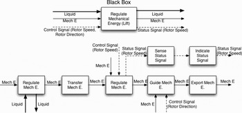
A functional model is a form-independent model that describes a system based on the functions that it performs (Otto & Wood, Reference Otto and Wood2001). Because of this, a functional model can be generated before components have been selected or a physical design exists. This model plots flows of material, signal, and energy as they pass through the system, are acted on by functions of the system, and then exit. These flows are generated from high-level customer needs, and are plotted on a black box model of the system, consisting of only the most basic function of the system. This general function is then further defined, following each individual flow from where it enters to where it leaves, generating chains of functions that act on that flow. These chains of functions are the combined to form the functional model of the system (Cross, Reference Cross2000; Otto & Wood, Reference Otto and Wood2001; Dym & Little, Reference Dym and Little2004). Figure 1 depicts an example of this for the main rotor of a helicopter. As shown in the figure, the main rotor regulates, transfers, regulates, guides, and exports mechanical energy.
A black box and functional model.

Although such a model is helpful, without a single language used consistently it is impossible to uniformly measure model results or accurately convey data to others. Therefore, to allow better communication of functional models, a functional basis was developed (Stone & Wood, Reference Stone and Wood2000; Hirtz et al., Reference Hirtz, Stone, McAdams, Szykman and Wood2002). This basis defines function “verbs” such as “import,” “convert,” and “mix,” and flow “objects” such as “energy,” “solid,” and “status signal.” By combining these into verb–object pairs, defined functions are created, showing not only what the function does but also what it acts on. With this functional basis in use, historical function data can be quantified uniformly and communicated clearly. This advantage allows the use of such conceptual design tools as the function failure design method (FDM; Stone et al., Reference Stone, Turner and Van Wie2004), the concept generator (Bryant et al., Reference Bryant, Stone, McAdams, Kurtoglu and Campbell2005), and the RED method (Grantham Lough, Reference Grantham Lough2005).
2.2. RED
RED collects failure data from historical events, and combines it with functional models to perform risk analysis as early as the conceptual phase of product design (Grantham Lough, Reference Grantham Lough2005). RED presents a listing of function–failure mode pairs and a listing of the consequence and likelihood of each pair as an integer from 1 to 5. It presents these results in both a list as well as plotted on a fever chart, making it easy to see where potential failures lie, and the overall risk of a failure in a system occurring. RED allows even novice engineers or those unfamiliar with the systems being analyzed to perform a detailed analysis on that system, as it identifies historical risks automatically. Further, RED provides multiple methods for calculating the consequences and likelihoods of the function–failure pairs, depending on whether the system is human centric or unmanned and whether it is a subsystem or system level design.
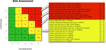
An example of a RED output is shown in Figure 2. Each function–failure mode combination is followed by two numbers: the consequence and likelihood, respectively. Each combination of consequence and likelihood corresponds to one of the colored grids on the fever chart. The number in each grid represents the number of function–failure pairs that have that consequence and likelihood, and the color of each grid gives the general risk of that pair. Red elements are high risk, yellow are moderate risk, and green are low risk. The 21 listed function–failure pairs in Figure 2 are only part of the total 377 pairs returned from RED, of which 9 are high risk, 147 are moderate risk, and 221 are low risk. A greater description of this RED output is given in Section 4.1.
The risk in early design output at the human centric, subsystem level for a turboshaft helicopter. [A color version of this figure can be viewed online at journals.cambridge.org/aie]

RED can detect specific function–failure pairs during the conceptual design phase; however, each entry returned is regarded as a separate and singular case, not part of any other failure (Grantham Lough et al., Reference Grantham Lough, Stone and Turner2006a). Thus, this method does not consider combinations of failures or their sequence.
2.3. ETA
ETA is a risk analysis technique that uses forward logic to plot a path from an initial failure to its potential outcomes (Frank, Reference Frank1999). Starting with the initiating failure, termed an initiating event, paths called branches are created along other events that can occur after the initiating event, in approximately chronological order. Each of these events is limited to an outcome of success or failure, creating a number of unique branches made up of the successes and failures of the entire chain of events (USNR Commission, 1975).
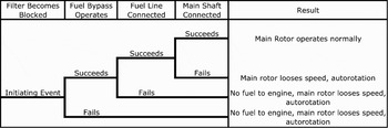
An example of an event tree is shown in Figure 3. Continuing with the previous example of the helicopter, this event tree starts with the initiating event of the fuel filter becoming blocked. Each of the events that follows, the fuel bypass operating, the fuel line remaining connected, and the rotor shaft remaining connected, are arrayed in chronological order. Of important note is that after the failures of the bypass and the fuel line, no other events are considered. After these events fail, each event that occurs after would be moot, as the system would have already failed. This pruning of the tree by removing branches that are either redundant or otherwise have no meaning can greatly simplify an event tree (Kumamoto & Henley, Reference Kumamoto and Henley1996). For this system, success is only achieved if the bypass operates, the fuel line remains connected, and the shaft to the rotors also remains connected.
Event tree analysis for a helicopter.

ETA focuses on chains of events, showing the many different paths that can lead to success or failure in a system. However, they cannot handle parallel events well, as they require the events used to be close to chronological order. Furthermore, they are binary in nature, and do not deal with events that have more than two outcomes. Event tree can also grow very large, numbering a total of 2n possible branches for n events (Kumamoto & Henley, Reference Kumamoto and Henley1996). Finally, this analysis focuses on events occurring in a mature system, making it ill suited for use during the conceptual design phase.
2.4. FTA
In contrast to ETA, FTA uses backward logic to plot a path from an ultimate failure to each of its potential causes (Vesely et al., Reference Vesely, Goldberg, Roberts and Haasl1981; Kumamoto & Henley, Reference Kumamoto and Henley1996). Beginning with the ultimate failure or fault, potential causes of the failure are found and plotted, using Boolean gates such as “And” or “Or.” For each of these causes, more faults are identified, until the most basic causes of the top fault are found. Using the tree structure and the probabilities of each fault occurring, the probability of each branch of faults leading to the top fault is calculated, as well as the total probability of the top fault occurring (Bedford & Cooke, Reference Bedford and Cooke2001).
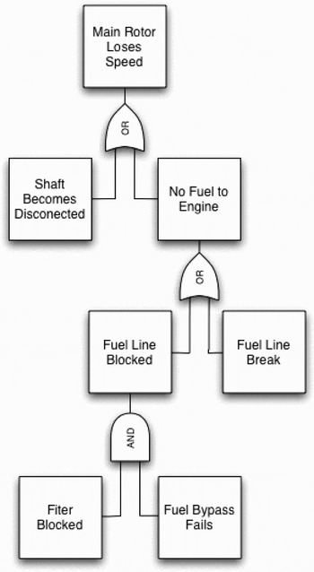
An example fault tree is shown in Figure 4. In this example, as in the previous, the helicopter is used. The top fault is actually the failure event from the previous example, the helicopter rotors loosing power. From this, there are two events connected by the Or gate, the shaft becomes disconnected and no fuel reaches the engine. As either of the events can cause power not to reach the rotor, the Or gate is used. Similarly, the faults that cause the no fuel fault can happen independently, also requiring the Or gate. The causes of the fuel line blockage, however, must occur together, and thus require an And gate. In addition to these two gates, there are additional gates, such and the “Exclusive Or” or “Inhibit” gates, but these gates are merely simplifications of combinations of And and Or gates or special circumstances (Kumamoto & Henley, Reference Kumamoto and Henley1996; Schellhorn et al., Reference Schellhorn, Thums and Reif2002).
Fault tree analysis for a rotor that is losing speed.

FTA, like ETA, focuses on chains of faults; however, unlike event trees, fault trees can handle parallel events well. Also, each fault tree created is specifically tailored to its top fault, focusing in on a particular fragment of the system rather than the system as a whole (Vesely et al., Reference Vesely, Goldberg, Roberts and Haasl1981). However, fault trees can become very complex and difficult to understand, and can become very large as the number of faults become large (Bedford & Cooke, Reference Bedford and Cooke2001). Fault trees are also acyclic, and cannot be used to model systems that can be kept running with repairs, instead requiring the model to treat the system as always failing or always succeeding if it fails (Anand & Somani, Reference Anand and Somani1998). Finally, although FTA does model chains of faults as they spread through a system, it, too, works best on a mature system, and is thus not suited for use in the conceptual design phase.
2.5. Change prediction
Change prediction uses the “common interfaces” between components as a means to track how changes can propagate in a design (Eckert et al., Reference Eckert, Clarkson and Zanker2004). This is based on the theory that changing a single component or system in a design effects other systems or components in the design through the interfaces common to each component, such as a shaft or common mounting. Based on the engineering opinions of a team of experts, data on the relationship of components in a complex design is collected, as well as the likelihood that a change in one component will propagate to anther it is dependent on. In addition, each component has a consequence of change representing the impact of that change to itself and other components. Using these three pieces of information, a model of the change in a system is made, consisting of trees that show all the ways that one component can be affected by another component. These trees are then used to calculate the combined likelihood and consequence of a change propagating from one component to another (Clarkson et al., Reference Clarkson, Simons and Eckert2001).
This method tracks changes to a design as they propagate through a system, and lists the most likely components to regulate changing if a single other component is changed. However, the data used is based solely on the opinions of experts, rather than historical data. In addition, this method requires that a similar design already exists, and cannot be used on an original design (Jarratt et al., Reference Jarratt, Stone, Clarkson, Parks and Eckert2002). Finally, although the method tracks the propagation of changes, it focuses on components rather than functions, and is thus not suited for use in conceptual design.
3. FUNCTION-BASED FAILURE PROPAGATION METHOD
Despite their advantages, each of the above failure analysis methods lack the ability to either be used during the conceptual design phase or the ability to analyze chains of failures. The function-based failure propagation method presented here attempts to remedy this by providing a means to analyze the likelihood of failures to propagate from function to function, as an addition to other methods such as RED to allow for a more complete picture of potential failures in a system during conceptual design.
3.1. Function-based failure propagation
During the conceptual design phase, only the component-independent functional model exists. Instead of components, functions representing the basic operation the system performs are used to model the product. These functions are linked by flows representing the materials, energies, and signals the system acts upon. As these functions are linked by their flows, the concept of the “common interface” from change prediction is extended to the functional model. Thus, to understand how a failure might propagate in a system, a common interface of the flows linking the functions is used to map out failure paths. Following this, a function that fails has a likelihood of propagating its failure to another function downstream along one of the flows connecting them.
These failure propagations can be mapped to a tree similar in nature to a fault tree, connecting functions with And and Or gates. Thus, for a single function, all of the potential root causes of its failure can be found using backward logic and the dependencies based on the common interface of flow. Once these trees exist, past data on failure propagation from a knowledge base is used to calculate likelihoods of propagation. These likelihoods can then be used to calculate the likelihood of a function failing because of another function's failure propagating to it.
3.2. New failure modes
It is assumed in this research that propagating failures can be initiated by any failure mode. Likewise, the failures caused by their propagation can also be any of the existing failure modes. However, there are two other ways that a failure can propagate to another function. These “new” modes are not traditional failure modes, in that the function they occur to is perfectly capable of carrying out its function. For these two failure modes, the failure is caused either by the lack of a necessary supply or as a “failure carrier” that causes a later function to fail because it operated normally.
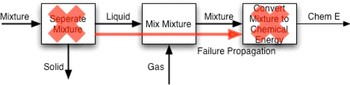
The first of these two new failure modes is one in which the function the failure propagates to continues to function normally. This “no failure” failure mode acts as a carrier that passes the failure off to another function, potentially causing it to fail. An example of this failure mode would be a fuel/air mixture chamber, represented by the function “mix liquid and gas” and shown in Figure 5. The flow of “mixture” represents liquid fuel mixed with contaminates. One failure mode of the function “separate mixture” might allow the mixture through without separating it. The function immediately downstream, “mix liquid and gas,” continues to perform its task normally, and thus does not fail. However, the function immediately after, “convert mixture to chemical energy” fails because of the potential contaminate in the mixture.
An example of “no-failure” failure mode. [A color version of this figure can be viewed online at journals.cambridge.org/aie]

The second of these new failure modes is failure because of no flow existing. Certain functions, when they fail, cause a flow that leaves the function to cease. Thus, any function that was connected to that flow downstream of that function would fail because there would be nothing for the function to operate on. The example shown in Figure 6 illustrates this failure mode. If the function “convert mixture to chemical energy” were to fail, there would be no new chemical energy leaving the function, resulting in a case where there is “no flow.” The function “convert chemical energy to mechanical energy” would also fail, because of no chemical energy being available to the function, which is necessary for the function to carry out its task. Likewise, “transfer mechanical energy” would also fail, as no mechanical energy exists to be transmitted.
An example of “no-flow” failure mode. [A color version of this figure can be viewed online at journals.cambridge.org/aie]

Each of these two failure modes allows the data collection procedure to go more smoothly. Without the “no-failure” failure mode, it would be impossible to advance passed functions that did not fail, yet help propagate the failure to others. Likewise, without the “no flow,” it becomes impossible to deal with functions that are working properly, but are not receiving the flow they need to truly “function.” These two new modes are essential to properly plot a path from the initial failure to the final failure in a system.
3.3. Data collection
Before function-based failure propagation is applied, data on the likelihood of failures propagating through functions must be collected. This data is a historical record of the number of times a failure has propagated along a particular path of functions in currently existing products. Using this data, the likelihood of such a propagation occurring again in a new conceptual product can be calculated. For this paper, the data used was obtained from National Transportation Safety Board accident reports covering Bell 206 helicopters. Function–failure mode combinations are identified from the failure reports such as this, and recorded. The path from the initial failure to the final failure is then identified and plotted on a functional model of the product, and each instance of propagation is recorded. These results are then tabulated into a matrix knowledge base (Grantham Lough & Krus, Reference Grantham Lough and Krus2007).
For any given function pair, there are many different possible failure modes that can propagate to the next function, as well as many different flows that the failure can propagate along. There is a good potential that each failure mode that can propagate has its own likelihood of propagation, and a specific flow that it propagates along. However, for simplicity of calculation, it is assumed that each failure mode has the same likelihood of propagation, and can propagate along any flow. The specific nature of the failure propagation, for example, either breaking a shaft or burning up a wire to stop a motor from functioning, is not as important at this stage as the fact that a particular failure can propagate. Further, past effects gathered in this way are representative of the functional, not component based model of that product. Propagations in past products that do not exist in a new conceptual product will not appear in the functional model, and thus not effect the analysis of the new product.
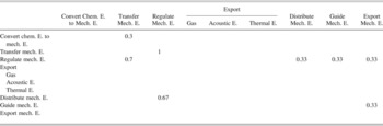
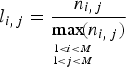
The likelihoods are calculated from the knowledge base matrix using a modified form of the likelihood mapping from (Grantham Lough et al., Reference Grantham Lough, Stone and Turner2006b) and shown in Eq. (1). In this equation, for an M × M knowledge base matrix, N, the likelihood for a given pair of functions i and j is l i, j, and n i, j is the value of the pair found in the knowledge base matrix. These likelihoods are then recorded into a likelihood matrix, L, such as one shown in Table 1. Along the left side are the functions that initiate the failure propagations, and across the top are the functions to which the failure propagates. The corresponding matrix entry is the failure propagation likelihood for the pair. The entire table of collected data is presented in Appendix A.
The data used in this paper are far from a complete database; there are many missing function pairs and pairs that have no data pertaining to them. Further, even more data for the function pairs that do exist needs to be acquired to truly verify their likelihoods. The goal of this work was not to create a complete knowledge base, but to demonstrate a method. For further reference, a more complete analysis of the data collection method and how it was used to create the knowledge base used can be found in Grantham Lough and Krus (Reference Grantham Lough and Krus2007). Over time, a more complete database will exist.
Part of collected failure propagation data

Note: E., energy.
3.4. Procedure
The procedure to perform function-based failure propagation starts with constructing the functional model. From this functional model, the dependencies of each function can be determined. Each function is directly dependent on functions that are connected to it by flows. Further, as flows in a functional model only “flow” in a single direction, functions are also dependent in this same direction. As shown by the sample functional model in Figure 7, function C is dependent on both functions A and B, and function D is dependent on function C. These dependencies are independent of the number or type of flow between each function.
An example functional model showing dependencies.

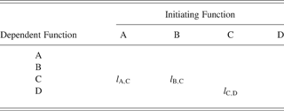
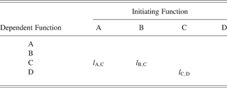
From this functional model, a functional dependency matrix is generated, using the flows as the common interface. The functional dependency matrix is populated with the likelihoods of propagation, taken from the historical failure knowledge base. As shown in Table 2, the three likelihoods from the example functional model have been placed into a functional dependency matrix. The initiating function of the pair is shown across the top, and the dependent function is shown along the left. Those places with no dependency are filled with zero, here left blank for clarity.
Example functional dependency matrix
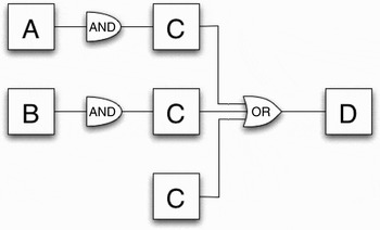
Using the functional dependency matrix, propagation trees are built for each function. Starting from the function of interest and using backward logic, a branch is created for each starting function that can spread backwards to the “root” function. For the functional model in this example, the propagation tree for function D is shown in Figure 8. Functions A, B, and C are all root functions whose failures can propagate to function D. However, functions A and B cannot propagate directly to function D, and must cause function C to fail, or bypass C through “no failure” first. Thus, there are three ways for function D to fail because of propagation: by [A and C] or [B and C] or [C].
The failure propagation tree for function D.

Using these trees, the total likelihood of failure propagation is calculated. As shown above, the tree is a combination of Boolean And and Or statements. Thus, using calculations for And and Or, shown in Eqs. (2) and (3) (Kumamoto & Henley, Reference Kumamoto and Henley1996), the direct likelihoods are combined into a single total likelihood. If in a branch there are multiple failure propagations that have to occur together, the And calculation is used. Likewise, any time the branch breaks into multiple paths, the Or calculation is used. In each of these equations, i, j, and k are functions, where the first subject is the function being propagated from and the second is the function being propagated to.
And operator:

Or operator:

For this example in Figure 8, function D has three branches, connected by the Or gate. Combining the three branches and using (2) and (3), the total likelihood of propagation for function D (L D) is as shown in Eqs. (4) and (5).


3.5. Linking to RED
Function-based failure propagation is not without its faults. Creating trees for every function in a functional model can be time consuming, even for small models, and some trees have the capacity to grow very large and complex. In addition, there is no way to currently add the consequence of failure to the calculation. However, by linking function-based failure propagation with other failure analysis methods, such as RED, these problems can be lessened, if not removed entirely.
The first problem is that of the time required to construct failure propagation trees for an entire functional model. The size and number of possible trees increases for each function added in a chain, and each possible branch that separates from that chain. For example, a chain of four functions with no branches would have three possible trees: one with three branches, one with two, and one with one. For small functional models with few functions, this can be performed quickly, but can rapidly become complex as the functional model becomes larger and more complex. In contrast, RED is a very rapid analysis method, requiring only the different functions of the product in question and only moments to perform the calculations. If a RED analysis is performed before attempting a function-based failure analysis, the RED results can point to the functions that have the highest likelihood of failure. Then, these functions can be focused on as the most likely initiating functions for the analysis. This allows the “trimming” of branches that are less likely to occur, allowing the analyst to focus instead on the most likely chains of function failure.
Finally, the consequence of risk can also be addressed by combining the analysis with RED. As above, RED illustrates the highest risk functions and failure modes. By applying RED results to the function chain, the best way to alter a design to prevent a chain of failures from occurring can be found.
Function-based failure propagation is only a portion of the conceptual design and analysis process. It requires work from other design methods such as the functional model and RED to make it complete, and eliminate many of its shortcomings.
3.6. Comparisons to other methods
Function-based failure propagation addresses many of the shortcomings of other failure analysis methods. The addition of chains of functions based on the functional model of a system allows the function-based failure propagation method to demonstrate failure propagation through a system. This provides forward logic failure propagation (similar to ETA). Moreover, the focus on system functions, rather than components, allows function-based failure propagation to be used during the conceptual stage of design.
The earlier initiation of the analysis enables more design decisions to focus on failure prevention. This type of preliminary failure of a conceptual design is very difficult in ETA, FTA, and change prediction analysis. Further, function-based failure propagation leverages the features of the RED method, as described in Section 2.2. RED augments function-based failure propagation by reducing the size and complexity of the analysis, a common complaint about ETA and FTA. Moreover, the use of a sufficiently populated historical knowledge base allows for a less subjective failure analysis.
4. VERIFICATION AND CASE STUDY
As a demonstration of how this method is useful as an analysis tool during the conceptual design phase, a verification and a case study are presented here. The method verification focuses on a Bell 206 helicopter, the same kind that the failure propagation data taken for this paper comes from. The design case study is of a thermal control subsystem, as a demonstration of how the method is used in a design setting.
4.1. Verification—Bell helicopter
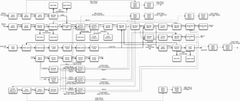
For the verification of this method, the same functional model used to collect data was used to perform an analysis, to compare the likelihood values calculated to the failure chains that occurred in the reports. As stated previously, the data collected was from the Bell 206-B series and 206-L series of helicopters. These helicopters are turbine powered commercial helicopters, capable of performing many corporate, law enforcement, military, and medical roles (Bell Helicopter Textron, 1997, 1999). The functional model shown in Figure 9 is one of the most important systems found in the helicopter, including the fuel and air intake systems, turbine engine, main and tail rotor assemblies, lubrication, control and sensor systems, the human interfaces, and the electrical system. The system takes in four flows: dirty air (gas–solid mixture), dirty liquid fuel (liquid–solid mixture), oil (liquid), and the human passengers and pilot. It exports eight flows: four status signals for important systems (fuel level, battery charge, and rotor speeds), two mechanical energy flows (the movement done by the rotors), a liquid flow (broken down oil), and the human passengers and pilot.
The functional model of a turboshaft helicopter.

A RED analysis of the system (Fig. 2) reveals that high cycle fatigue presents the greatest risk to the helicopter, with 9 functions failing because of it (Fig. 2, shown in red). In terms of failure propagation, 5 of those functions (“export solid, mechanical energy, liquid, and thermal energy” and “secure solid”) will not propagate, as they are the last functions in their chains or outside the scope of this analysis. The remaining 4 functions (“import liquid,” “transfer mechanical energy,” “distribute mechanical energy,” and “guide liquid”) are positioned in the middle or at the beginning of chains of functions and have a chance to propagate their failures to other functions. Below these 9 failures are the 12 most likely moderate risk function failure pairs (Fig. 2, shown in yellow). Of those 12, 8 are repeats of the functions above (all save “distribute mechanical energy”), failing because of yielding. Of the remaining 4 failure pairs, 3 fail because of high cycle fatigue, and 1 fails because of yielding. Again, it is assumed that each failure mode has an equal likelihood of propagating its failure. Thus, the failure modes high cycle fatigue and yielding are treated as having the same likelihood of propagation.
From the RED analysis as stated above, the most important initiating functions of a chain would be “import liquid,” “transfer,” and “distribute mechanical energy,” and “guide liquid” because they have the highest likelihood. Of secondary importance, but also necessary of consideration is the function “guide mechanical energy.” All other functions either end their chains or are outside the scope of this analysis.
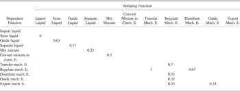
The functions that the system is most dependent on are “export mechanical energy,” as this represents the rotors that keep the helicopter airborne and steering properly, and “convert mixture to chemical energy,” which is providing fuel to the engine, which powers the rest of the system. Thus, failures that can propagate to these systems are the ones that the analysis should focus on, as these chains of failure present the greatest possible damage to the system. With these functions as a guide, a functional dependency matrix is built, using the function chains from the model that start with the above initiating functions as “roots” from the RED analysis, and end with the most critical functions, “export mechanical energy” and “convert mixture to chemical energy.” This matrix is shown in Table 3.
Helicopter functional dependency matrix

Note: E., energy.
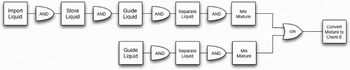
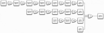
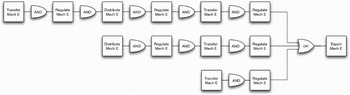
Based on this functional dependency matrix and the functional model, propagation trees are created. Starting with the most important functions, “export mechanical energy” and “convert mixture to chemical energy,” backward logic is used to trace the failure of the critical function back to the “root” failures. These three trees are shown in Figures 10, 11, and 12. These figures represent the fuel intake subsystem, the main rotor subsystem, and the tail rotor subsystem, respectively. The fuel intake chain depends on the functions “import liquid” and “guide liquid,” and thus has two branches. The main rotor has the branches with both the most and least functions in its chain, and is dependent on “transfer mechanical energy” and “guide mechanical energy.” For this tree, however, these two functions start three chains. For the final tree, the tail rotor, there are again two chains for the two initiating functions, which are the same as for the main rotor.
The fuel intake propagation tree.

The main rotor propagation tree.

The tail rotor propagation tree.

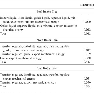
Using these trees and the FDM, the likelihoods of each chain failing are calculated. The collected results for each tree are presented in Table 4. The values are the likelihoods of a branch failing, and each of the totals represents the total likelihood of any branch failing in a subsystem, and illustrates the subsystem with the greatest likelihood of failure because of propagation. Of the seven possible results returned by the analysis, the two shortest branches (“guide mechanical energy” propagating directly into “export mechanical energy” in Fig. 10 and the shorter tail rotor branch in Fig. 11) are the most likely to fail. Despite this, the most frequent occurrence among the data from the NTSB reports is guide liquid failing, and then propagating to the rest of the system. The reason the other two trees have far larger likelihoods is that any damage to the engine will cause the rest of the functions in both rotor chains to fail. Although “transfer mechanical energy” propagated to “regulate mechanical energy” with the most frequency, it was rarely the initiator function, based on the analysis of the NTSB failure reports.
Helicopter analysis results

Based on this analysis, additional fail-safes should be placed to prevent “transfer mechanical energy” from failing because of high cycle fatigue and yielding. One solution would be to improve the design of the shafts of the helicopter to have a greater life cycle. These results verify the method as a useful design tool. Although it was unable to verify the most frequently initiating failure, it did identify the most frequently occurring chain of failures: those of the rotors. The rotors failed more frequently than any other system, initiated by the “guide liquid” function as well as others.
Of particular note is the longest branch of the fuel intake tree in Figure 9. The likelihood of propagation from “import liquid” to “store liquid” is zero, as nowhere in the collected data does the import function fail, and thus cannot propagate. This is one of the limitations of this method; if the data does not exist in the database and no similar function pairs exist, the likelihood of the pair is either zero or must be totally subjective. One possible solution for this is to consider a worst-case scenario and set unknown likelihoods to 1, assuming that the failure would always propagate, or that all failures have an equal likelihood of propagation. Although not as historically accurate, such a value would give a useful comparison for when the data do exist.
4.2. Case study—Thermal control subsystem
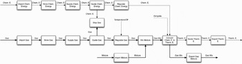
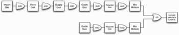
As a case study, this method was applied to a thermal control subsystem functional model. This type of subsystem may be used on spacecraft designed by NASA's Jet Propulsion Laboratories Concept Design Team, Team X (Deutsch & Nichols, Reference Deutsch and Nichols2000). This system is an example of what would be found in several different kinds of spacecraft, including launch vehicles (Van Wie et al., Reference Van Wie, Grantham Lough, Stone and Barrientos2005). The functional model of this system is shown in Figure 13. The system takes in chemical energy, gas, and a mixture, and exports thermal energy and gas. These flows will be the common interfaces that are assumed to propagate failure. For example, the gas flow passes through the functions “import,” “store,” “supply,” “guide,” “regulate,” “mix,” and “stop.” For example, if any of the functions in this chain failed, the gas flow could potentially propagate that failure to other functions in the chain, or further.
The thermal control subsystem functional model.

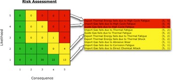
Once the functional model has been constructed, a RED analysis determines functions at risk of failure in the system. From the RED results presented in Figure 14, the most likely functions to fail are “export thermal energy,” “import gas,” and “guide gas,” all because of high cycle fatigue. In addition to these, each of the functions is slightly less likely to fail because of thermal fatigue, but still more likely to occur than other function–failure mode pairs. Of these, “export thermal energy” will not propagate to other functions in the system as it is the final function in the model. Thus, this analysis will focus on chains with “import” and “guide gas” as “roots” of the tree.
Risk in early design analysis for a thermal control subsystem. [A color version of this figure can be viewed online at journals.cambridge.org/aie]

Another important point is to consider the potential roots of the propagation trees, or the functions the system is most dependent on. From the black box model of the thermal control subsystem, the general function of the system is to “convert chemical energy to thermal energy.” Thus, any failure that causes this function to fail causes the system to fail. This function should be the tip propagation tree that is constructed for this analysis.
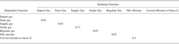
Once the “tips” of the branches and the “roots” of the trees have been determined, the functional dependency matrix can be constructed and propagation trees built. For the thermal control subsystem, the propagation tree has two branches, each one starting from “import” or “guide gas.” This tree is shown in Figure 15, and the FDM relevant to the tree is presented in Table 5, again taking the likelihoods calculated from the helicopter accident data.
The propagation tree for the thermal control subsystem.

Thermal control subsystem functional dependency matrix for relevant functions

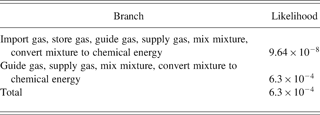
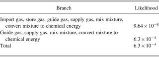
Using the collected likelihood values from the FDM and the propagation tree, the total likelihood value for each branch can then be calculated, as well as the total likelihood that either initiating function propagates its failure to the “convert” function. A sample calculation of the total likelihood of both branches is shown below in Eqs. (6) through (10). The likelihoods of both branches as well as the total likelihood of propagation are shown below in Table 6. As shown in the table, the likelihood of “guide gas” propagating its failure to “convert mixture to chemical energy” is four orders of magnitude higher than the longer branch. When they are combined together to form the total likelihood of propagation for the tree is approximately the same as the likelihood of the shorter branch. Thus, if prevention methods are required, “guide gas” should be made more resistant to high cycle fatigue and thermal fatigue. By preventing the failure of this function, the propagation is most likely not to occur, as “import gas” is not likely to propagate its failure.





Thermal control subsystem analysis results
5. CONCLUSION
Function-based failure propagation gives a more complete picture of the system risk in conceptual design, as it looks at the failures of chains of functions. It provides not only the total likelihood that a function will have failure propagated to it, but also the likelihood that any one function will propagate a failure as based on historical data of failures. It serves as a starting point to further risk analysis and design decisions.
Although the method has these strengths, it has weaknesses. However, by pairing this method with other risk analysis techniques, the weaknesses are lessened. By defining likelihoods of propagation based on historical data, the subjectivity of the analysis is decreased, and by pairing the method with RED, the analysis can be focused on a particular portion of the system, saving time, as well as identifying consequences to the functions that fail. However, even when paired with RED, the data are still based on recorded failures and cannot accurately anticipate unforeseen or new failure propagations not recorded. Again, further analysis is required to catch these possible failures before they can occur.
Currently, this method only focuses on the likelihoods of failure propagation. Future work on adding the consequence of failure to the method without the inclusion of another method is required to make the method truly a standalone technique. Finally, additional failure propagation data are required to fully populate the database and help eliminate subjectivity in the analysis.
ACKNOWLEDGMENTS
The authors acknowledge University of Missouri Research Board Grant R5008065-RAW54 and the assistance of Daniel Abbott.
Daniel Adam Krus completed his BS in December 2005 and his MS in May 2007, both in mechanical engineering at the University of Missouri–Rolla [now the Missouri University of Science and Technology (MS&T)]. He is currently pursuing a PhD in mechanical engineering at MS&T, with an interest in failure and risk analysis and prevention.
Katie Grantham Lough has been an Assistant Professor in the Interdisciplinary Engineering Department of MS&T since 2006. She received her PhD in mechanical engineering at the University of Missouri–Rolla in 2005. At MS&T she develops and applies risk assessment methodologies to product design principles and leads efforts in the design of a variety of products from biomedical devices to the sustainable technologies of fuel efficient cars and solar houses. Prior to joining the MS&T faculty, Dr. Grantham Lough served as a Research Scientist for 21st Century Systems, where she added risk assessment techniques to their existing defense software products. She was involved with projects to identify both hardware and software failures in mechatronic systems. Her current research interests are product design theory and methodology, sustainable design, as well as failure and risk identification and mitigation.
APPENDIX A
Collected failure data from NTSB reports