I. INTRODUCTION
In the absence of a template, like-sized spherical particles spontaneously assemble into close-packed face centered cubic (fcc) or hexagonally close-packed (hcp) arrays, generally with (111) orientation against a planar deposition surface, if one is available. Taken in analogy with atomic crystal structures, these well-known structures are interesting but constitute a very small subset of the ordered structures that might be possible—they are the colloidal equivalent of elemental fcc and hcp metals among the much larger constellation of all known crystal structures. In particular, non-close-packed colloidal crystals are difficult to fabricate, although they are of interest for their optical and other properties. The diamond cubic structure is an exemplar of particular interest due to its complete photonic band gap.Reference Moroz1, Reference Ho, Chan and Soukoulis2 Researchers have also used spontaneous self-assembly of particles (through spin-coating,Reference Xia and Brueck3, Reference Sharma, Yan, Wong, Carter and Chiang4 convective assembly,Reference Jiang, Bertone, Hwang and Colvin5, Reference Zhou and Zhao6 etc.) to create dense-packed binary colloidal crystals. In this instance, a non-close-packed crystal of one particle type can be obtained from the binary structures by removing the other particle type. Another non-close-packed heterogeneous colloidal crystal is the ionic colloidal crystal, invented by Maskaly et al.Reference Maskaly, Chiang, Carter and Garcia7, Reference Maskaly, Garcia, Carter and Chiang8 This concept uses simultaneous attractive and repulsive interactions between colloidal “ions” to form the colloidal crystalline equivalent of ionic crystals. Although ICCs can become unstable on removal of the solvent,Reference Leunissen, Christova, Hynninen, Royall, Campbell, Imhof, Dijkstra, van Roij and van Blaaderen9 their formation suggests that interparticle colloidal interactions may play a key role in the formation of non-close-packed structures.
Templated assembly adds additional degrees of freedom in the fabrication of colloidal crystals. The ability to direct small particles into positions on a substrate provides a facile approach to creating various particle-based small-scale devices,Reference Cho, Wartena, Tobias and Chiang10 biological sensors,Reference Haes, Hall, Chang, Klein and Van Duyne11 as well as electronicReference Cui, Bjork, Liddle, Sonnichsen, Boussert and Alivisatos12 and photonic crystals.Reference Vlasov, Bo, Sturm and Norris13, Reference Wong, Kitaev and Ozin14 It has recently been proposed that templates can also be used to fabricate non-close-packed 3D crystals.Reference Wang and Mohwald15, Reference Dziomkina and Vancso16 Robotic and optical tweezer based assembly have been used for such purposes. For instance, Santamaria et al.Reference Garcia-Santamaria, Miyazaki, Urquia, Ibisate, Belmonte, Shinya, Meseguer and Lopez17 fabricated a diamond cubic structure from silica particles on a template with holes arranged in (100) symmetry. They fabricated a 3D body centered cubic (bcc) structure by robotic placement of polystyrene (PS) and silica particles one at a time. Subsequently, the PS particles were removed. This is a slow process of limited scalability. Scalable methods for fabricating stable non-close-packed ordered colloids have yet to be developed.
In this paper, we report on progress in this direction through the templated assembly of ordered colloidal heterostructures. PS and silica particles of the same sign of surface charge were used (i.e., the net interparticle interactions are repulsive throughout). A silicon wafer with holes patterned in (100) symmetry is used as a template. Particles are arranged in the heterostructure akin to the pattern on a checkerboard; PS particles reside in every other hole and silica particles fill the remaining holes. A two-step convective assembly process is used to form this structure. In the first step, it is shown that PS particles form a sparse structure if the Debye length (κ−1) of the solvent and concentration of particles in the suspension are correctly controlled. Domains with a sparse arrangement of PS particles are hundreds of micrometers wide; these domains are referred to as L1-PS. In the second step, convective deposition is used to fill the remaining holes with silica particles. The resulting 2D heterostructure domains forming a complete first layer (hereafter, referred to as L1) are tens of micrometers wide. Thus a method for producing 2D ordered heterostructures, useful in their own right, was first demonstrated. On top of the L1 layer, we then formed a second layer, L2, having the same checkerboard pattern of PS and silica particles. The L2 layer is displaced from the L1 layer to form a partial bcc structure. Upon removing the PS particles from this two-layer heterostructure, we are able to form a half-unit-cell precursor to the diamond cubic structure. While continued layer-by-layer assembly in this manner would clearly result in a 3D diamond cubic structure, limitations on the size of the ordered domains due to stick-slip phenomena during the convective deposition of particles, prevented continued assembly.
II. EXPERIMENTAL
A. Template preparation
Silicon templates were prepared using interference lithography. A 4-in silicon wafer was spin coated with PS4 negative photoresist. After baking for 90 s at 90 °C, this was exposed in a 325 nm wavelength, Nb-YAG laser. In order to create a square pattern of holes, the wafer was exposed, then rotated 90° and exposed again, the exposure conditions being 33 s at 0.23 mW in each case. The resulting pattern was baked for 90 s at 110 °C and then developed in CD-26 developer for 60 s, creating the hole pattern in the resist layer with a pitch of 330 nm. The sample was then plasma-etched with CF4-O2 plasma at 20 mTorr for 3 min to etch the pattern of holes into the silicon surface to a depth of 45 nm. The photoresist was then removed by treating in O2 plasma at 20 mTorr for 7 min.
B. Colloidal particles
Suspensions of monodisperse 250 nm diameter polystyrene beads (sulfate functionalized, ζ = −52.56 mV at κ−1 = 127 nm, σ = 5%, Z = 300, and –0.019 C/m2 surface charge density as measured by the manufacturer) and of monodisperse 250 nm diameter silica beads (ζ = –45.54 mV at κ−1 = 127 nm) were obtained from Molecular Probes Incorporated (Carlsbad, California) and Corpuscular Incorporated (Cold Spring, New York), respectively.
C. Debye length control
In order to increase the Debye length of the space-charge interaction between particles to a value large enough (~200 nm) to produce significant particle-particle repulsion at separations commensurate with the size of the particles (250 nm) and the pitch of the template (330 nm), the salt concentration in the starting particle suspensions was reduced by dialysis.Reference Maskaly18 The conductivity of the DI water used to dilute the suspensions was measured (YSI 3200 Conductivity Instrument) in the absence of particles; the corresponding salt concentration was used to infer the Debye lengths.
Dialysis was first used to lower the salt concentrations in the starting particle suspensions. The suspensions were dialyzed against DI water in Float-a-lyzer dialysis bags (Spectrum Labs, Dominguez, CA), allowing salt ions to diffuse into the DI water while retaining the particles. The salt concentration of the DI water was tracked by measuring its conductivity, and dialysis was continued until no further change in conductivity was detected. Then, the particles were diluted to the desired low concentrations with the reference DI water. In order to explore the effect of smaller Debye lengths, salt (KCl) was added back in some experiments.
D. Convective assembly of particles from suspension
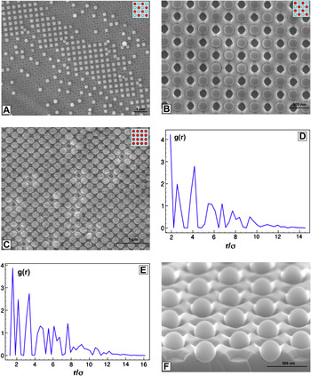
Particles were assembled onto the template through a convective assembly process in which the templates were attached in vertical orientation to the walls of a beaker containing the particle suspension, and the particles were allowed to coat the template by slowly withdrawing the suspension. For PS particle assembly, a starting 8 vol/vol% suspension was highly diluted in DI water (Debye length = 204 nm) to 0.01–0.1 vol/vol% concentrations. Convective assembly was conducted with the apparatus being held in a water bath at 35 °C. The suspension was pumped out at a rate causing the meniscus to recede at a velocity of 46.1 μm/min. The L1-PS pattern shown in Fig. 1(b) is an example of the sparse ordering we sought.
Impact of polystyrene (PS) particle concentration on templated ordering produced by convective deposition, with a constant Debye length (~200 nm). (a, b, c) SEM micrographs of the particle ordering obtained when PS particles are assembled from suspensions with 0.01 vol/vol%, 0.025 vol/vol%, and 0.1 vol/vol% particle concentration, respectively. Ordered 50% occupancy of sites is obtained at the first two concentrations, whereas the highest concentration results in complete occupancy. (e, f) The pair distribution functions (PDF) for the PS particles in (b, c) are plotted, respectively. (f) Perspective view of the ordered, 50% occupied template.

Slightly different experimental parameters were used for silica particle assembly in the L1 and L2 layers. For L1 deposition, a starting 5 vol/vol% suspension of silica was diluted in DI water to 0.025 vol/vol%. A beaker containing this suspension and already-coated L1-PS starting templates was placed in a water bath at 50 °C. The suspension was pumped out at a rate producing a meniscus velocity of 46.1 μm/min. For coating the L2-PS layer, the only change in process parameters was a slower speed of PS suspension withdrawal producing a meniscus velocity of 23.3 μm/min. After depositing the L2-PS layer, and prior to depositing the L2-silica layer, the template was dip-coated in a 3 wk/vol% suspension of poly(allylamine hydrochloride) (PAH) for 10 min, to reduce electrostatic repulsion between particles. The silica particles were then deposited under otherwise the same process conditions. The removal of PS particles from the deposited structures was accomplished by exposure to O2 plasma at 20 mTorr for 7 min. Imaging of all of the above structures was done using a Zeiss scanning electron microscope (Thornwood, NY).
III. RESULTS AND DISCUSSION
Several dozen particle deposition experiments were conducted to identify the key parameters and to systematically determine the experimental conditions under which optimal ordering occurs. We first discuss general requirements for obtaining particle ordering on the templates. Surface treatment of the starting template plays a key role, since a low contact angle is required in convective deposition to assemble a monolayer of particles. In contrast, convective assembly on a hydrophobic template (contact angle 30°–40°) leads to the assembly of multilayers. Prior to use, we treated our templates with O2 plasma for 5 min. Contact-angle measurements confirmed that the resulting receding contact angle of water was 0.80° on average. In between convective deposition steps, we also treated the partially coated templates with O2 plasma, as discussed in the next paragraph.
In order to obtain sparsely ordered L1-PS during the first particle deposition, we found that it is essential to use templates having a certain pitch (periodicity) and hole diameter relative to the particle diameter (250 nm). For a Debye length of ~200 nm, the conditions for optimum ordering were found by systematically varying the following two ratios:

The largest ordered domains in the initial L1-PS layer were obtained for λ1 = 0.80 and λ2 = 1.32. When λ1 is <0.4, we found that the relief features on the template were unable to trap particles, and the deposited particles formed domains with a close-packed arrangement of particles as one would normally get on a flat surface due to capillary forces during drying. On the other hand, when λ1 is >1.0, ordered L1-PS domains formed but were smaller.
Even when monolayers of particles do form, convective assembly onto substrates is typically characterized by the formation of bands of deposited particles separated by regions without any particles. An example of a band of sparsely ordered particles can be seen in Fig. 1(b). The banding is attributed to the stick and slip of the meniscus on the template.Reference Teh, Tan, Wong and Li19, Reference Watanabe, Inukai, Mizuta and Miyahara20 We may use the following geometric parameters to characterize the effects of stick and slip:
λband = Average center-to-center distance between two bands
δband = Average width of a band
ϕsparse = Average area of a band occupied by the ordered sparse pattern
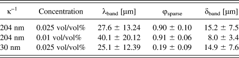
The values of these parameters in turn were found to depend on the Debye length and particle concentration, as summarized in Table 1. As we show, the dimensions of the deposited bands are critical for layer-by-layer assembly, since subsequently deposited layers also exhibit banding, and continued ordering of particles can only be accomplished where the bands overlap.
Variation in λband, ϕsparse, and δband at different Debye lengths and concentrations for 250 nm PS particles.

For a given Debye length and template periodicity, the structures obtained also depend on the concentration of particles in the suspension. Figure 1 shows scanning electron microscopy (SEM) micrographs of the ordered PS layer obtained when the Debye length was fixed at 204 nm and the concentration of particles was systematically increased from 0.01 vol/vol% [Fig. 1(a)] to 0.025 vol/vol% [Fig. 1(b)] to 0.10 vol/vol% [Fig. 1(c)]. The inset in each of these figures shows schematically the arrangement of PS particles on the template. At the two lower concentrations, the desired sparse ordering is found within the bands where particles have been deposited. However, for the highest particle concentration, Fig. 1(c), complete filling of the template sites is observed despite the interparticle repulsion. The pair distribution functions (PDF) for the PS particles in Figs. 1(b) and 1(c) are plotted in Fig. 1(d) and Fig. 1(e), respectively, and a perspective view of the ordered, 50% occupied template is shown in Fig. 1(f).
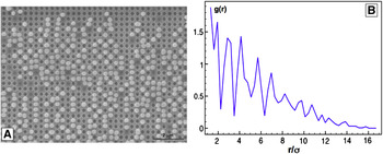
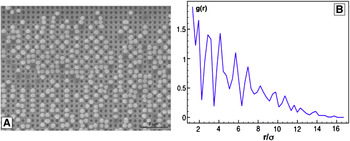
The effect of a decreasing Debye length is seen in Fig. 2, in which the PS particle concentration is 0.025 vol/vol%, identical to Fig. 1(b), but the Debye length has been decreased from 204 nm to 30 nm by the addition of KCl. All other experimental conditions were the same. The absence of sparse ordering like Fig. 1(b), is evident in the SEM image in Fig. 2(a) as well as the pair distribution function in Fig. 2(b). This shows clearly that like-charge repulsion between the deposited particles is key to obtaining sparsely occupied yet ordered structures.
(a) Upon decreasing the Debye length from 204 nm to 30 nm by the addition of KCl salt, the sparse ordering due to electrostatic repulsion between depositing PS particles is lost. (b) PDF for the arrangement of PS particles in (a).
We next address the deposition of silica particles to fill the vacant sites in the L1-PS layer, followed by deposition of PS and silica to form the L2 layer. Due to stick and slip of the meniscus along the direction of solvent withdrawal, the first deposition produced ordered L1-PS domains that were much longer than they are wide. Typical domains were ~15 μm wide in the drawing direction (δband in Table I) but hundreds of micrometers long perpendicular to it, restricted by the edges of the template. This L1-PS structure served as the starting template for the deposition of silica particles. Before this deposition, the L1-PS starting template was exposed to O2 plasma for 10 s, resulting in a receding water contact angle of ~5°. Silica particles were deposited at 50 °C from a 0.025 vol/vol% suspension at 46.1 μm/min meniscus velocity. The deposited particles, forming L1-silica layers, also formed in bands, within which the desired filling of unoccupied sites in the ordered L1-PS layer could be obtained under suitable deposition conditions. We found that increased silica particle ordering was obtained if the electrostatic repulsion between particles was reduced by dip-coating the template in a 3 wt/vol% suspension of poly(allylamine hydrochloride) (PAH) for 10 min, prior to depositing L2-silica. We also found that when the deposition of silica particles was carried out at 35 °C instead 50 °C, the silica occupied a lower density of the available sites in the L1-PS layer. This was attributed to a higher sedimentation rate of the silica particles from suspension at the lower temperature, resulting in a lower effective particle concentration. Various methods have been used to reduce sedimentation of silica; most researchers use silica dispersed in ethanol instead of waterReference Hoogenboom, Retif, de Bres, van de Boer, van Langen-Suurling, Romijn and van Blaaderen21 since the higher volatility of ethanol causes a greater number of silica particles to be convectively transported to the meniscus. Other researchers have assembled silica particles on a horizontal template, using gravitational force to their advantage.Reference Hoogenboom22 In the present experiments, ethanol was not a suitable solvent since PS particles are partially soluble in it, and ethanol is also absorbed, causing the particles to swell. Assembly by gravitational settling was also not effective since unlike vertical convective deposition, single monolayer thicknesses could not be obtained.
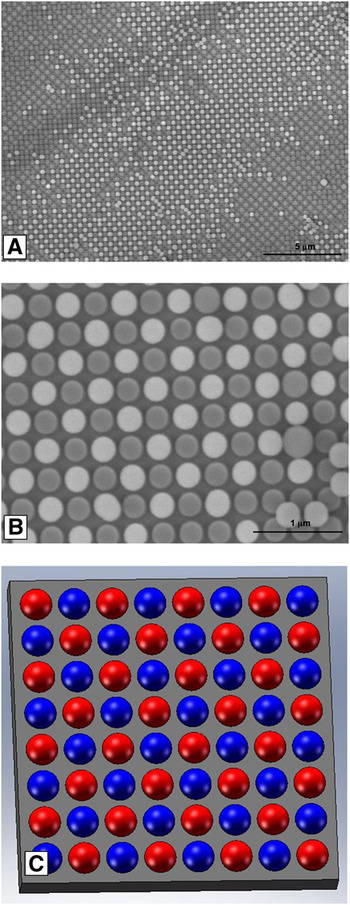
Figure 3 shows the 2D ordered heterostructure of PS and silica, which we will refer to as L1, that is obtained when the deposition conditions are controlled as described above. These ordered regions are observed where L1-PS bands overlap with L1-silica bands, and consequently are smaller than the initial L1-PS bands, being typically 10 μm wide and tens of micrometers long. Figures 3(a) and 3(b) are top view SEM images of a typical L1 domain; the gray particles are PS while the white particles are silica. Figure 3(c) shows schematically the arrangement of PS and silica particles.
(a) SEM micrograph showing a complete L1 ordered arrangement of PS and silica particles, obtained by deposition of silica particles in the unoccupied sites in Fig. 1(b) by second convective deposition. (b) Higher magnification image showing L1 arrangement of PS and silica particles. (c) Schematic showing the ordering of PS and silica particles.

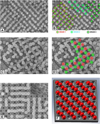
We now turn to the deposition of a complete 2D heterostructured layer of PS and silica, L2, on top of the ordered L1 layer. This was fabricated in the same manner as the L1 layer. An ordered layer L2-PS was first deposited, followed by deposition of an L2-silica layer. The substrate with the deposited L1 layer was first exposed to O2 plasma for 10 s to ensure a low suspension contact angle (~5°). The same 0.025 vol/vol% aqueous suspension of PS particles used to fabricate the L1-PS layer in Fig. 1(b) was used to convectively deposit the L2-PS layer. Stick and slip of the meniscus again resulted in the formation of bands of PS particles, typically 5 μm wide. Figure 4(a) shows a region where the L2-PS layer has been deposited. For viewing clarity, the PS particles in the second layer have been colored in green in Fig. 4(b). It is seen that each of the L2-PS particles occupy a saddle position where it is coordinated below by two PS and two silica particles in the L1 layer. Also, Fig. 4(b) shows that there are three distinct domains or grains of ordered L2-PS in the imaged region, with Grain 1 having a few unoccupied PS sites. In this example, the meniscus withdrawal speed was 23.3 μm/min. At a faster rate of 46.1 μm/min, the L2-PS domains were only a few particles wide, whereas at lower withdrawal rates than 23.3 μm/min, bands of close-packed particles began to form.
Deposition of a second checkerboard ordered layer of PS and silica, L2, on top of the first ordered layer enables the fabrication of a non-close-packed multilayer structure. (a, b) The structure after an ordered L2-PS layer has been deposited on a well-ordered L1 layer. Three domains or “grains” are identified in color in (b). (c, d) Deposition of silica particles in the unoccupied sites of the second PS layer produces domains of a complete second checkerboard layer, L2. (e) The removal of the PS particles by O2 plasma oxidation results in a non-close-packed structure that is a half-unit-cell of the diamond cubic structure. (f) Schematic view of the final structure, rotated 45° from the view in (e).

After deposition of L2-PS, the substrate was again exposed to O2 plasma for 10 s prior to silica deposition. The largest bands of L2-silica were obtained if the substrate (having L1 + L2-PS) was first dip-coated in a 3 wt/vol% suspension of poly(allylamine hydrochloride) (PAH) for 10 min. We believe that the PAH increases the ionicity of the solvent and promotes hard spherelike interactions between the particles, while still preventing coagulation due to the steric hindrance that exists between particles having an adsorbed layer of PAH.Reference Caruso, Lichtenfeld, Giersig and Moehwald23 Fig. 4(c) shows a typical domain in which there is L1 + L2 ordering. For better visual contrast, Fig. 4(d) shows the PS and silica particles in the L2 layer in green and red, respectively. In the final step of our process, O2 plasma was used to remove the PS particles, leaving silica particles intact. Figure 4(e) shows a top view of the resulting 3D domain of non-close-packed silica particles, which has the structure of a half-unit-cell of the diamond cubic structure. A schematic, perspective view of this structure, rotated 45° from Fig. 4(e), is shown in Fig. 4(f).
IV. SUMMARY AND CONCLUSIONS
We have demonstrated the templated, layer-by-layer assembly of ordered heterogeneous colloidal crystals using two particle types and in which there is repulsive electrostatic interaction between particles. By controlling the range of the electrostatic interactions (Debye length) relative to the particle size and template periodicity, the particle concentration, and other parameters in the convective deposition process, the ordered partial occupation of the initial template as well as subsequently deposited layers is achieved. Upon depositing two complete binary particle layers having checkerboard order, and removing one particle type (PS), a half-unit-cell of the diamond cubic structure was obtained. To our knowledge this is the first demonstration of colloidal self-assembly to obtain a non-close-packed multilayer structure. The approach demonstrated here is facile, scalable, and can potentially produce 2D and 3D ordered colloids of a range of structures, guided by the template geometry. We also showed that stick-slip of the meniscus is the main impediment in getting larger ordered domains along the direction of withdrawal in convective deposition. Future work will be focused on removing this limitation and enabling growth of ordered colloids of large lateral extent.
ACKNOWLEDGMENT
This work was supported by the Singapore-MIT Alliance (SMA).