Nomenclature
- DBD
-
dielectric barrier discharge
- SDBD
-
surface dielectric barrier discharge
- EHD
-
electrohydrodynamic
- AC
-
alternating current
- W
-
watt
-
 ${F_{modulation}}$
-
modulation frequency
- A/D
-
analog/digital
-
${C_P}$
-
pressure coefficient
- AOA
-
angle-of-attack
- C
-
chord
- PSJ
-
plasma synthetic jet


Greek symbol
-
$\alpha $
-
angle-of-attack

1.0 Introduction
The ability to manipulate a flow field around a body will give rise to significant economic and operational benefits. Hence, different approaches have been under attention to control the flow separation during recent decades [Reference Gad-el-Hak25]. Active and passive flow control are two types of well-known technologies used to deal with the boundary layer characteristics in order to retard or develop laminar-turbulent transition, to increase lift/reduce drag and to prevent vibrations and noises through controlling flow instabilities [Reference Moreau42, Reference Neretti44]. In contrast to passive flow control procedures, which cause additional drag, the active flow control can be used in situ, where its operation is actually required. This feature has made the active flow control a desirable method in spite of the external energy requirement. A comprehensive review of different flow control approaches can be found in the book of Gad-El-Hak [Reference Gad-el-Hak25]. Among different means of active flow control, the novel technique, based on atmospheric pressure discharges such as corona discharges, DBDs and arc discharges, has revealed a great potential for flow control purposes. In this regard, the SDBD in an asymmetric arrangement has been under great concern during twenty last years and also in the present paper. It is typically made up of two electrodes, one is exposed to air and the other is buried by a dielectric layer. By applying a sufficient AC high voltage to the upper electrode and connecting the lower one to ground, an ionised air will appear above the dielectric surface. As the result of momentum transfer of the plasma accelerated particles, especially that of the ions to the neutral molecules, the ambient air is entrained and a wall-jet is induced. This secondary flow, called electric wind or ionic wind, interacts with the flow of the boundary layer to modify its characteristics. This new idea was first proposed due to the attempts made by Roth et al. [Reference Roth48, Reference Roth50]. The authors have subsequently explored various aspects of the subject, including its underlying physics, interaction mechanisms, diagnostic methods for characterisation and flow control capabilities [Reference Corke and Post15, Reference Corke16, Reference Kotsonis31, Reference Moreau42]. The surface DBD has been widely developed as an alternative to other active flow control devices because of its simplicity in design and construction, flexibility in mounting on different surfaces, fast response to flow variations and low weight. Moreover, studies on the EHD force, generated by the SDBD, have revealed that it is clearly dependent on the electrical parameters [Reference Boeuf11, Reference Enloe19, Reference Mahdavi and Sohbatzadeh37, Reference Roth49]. Therefore, the completely electronic nature of the DBD plasma actuator provides the advantage of optimising its operation just by adjusting the electrical parameters. The experimental investigations have demonstrated the velocity of the induced wind as a function of the input electrical factors such as the applied voltage amplitude, voltage waveform, AC carrier frequency and pulsed excitation [Reference Benard and Moreau9, Reference Kotsonis and Veldhuis32, Reference Kriegseis33, Reference Mahdavi and Sohbatzadeh37, Reference Singhal55]. The AC frequency of the input signal determines the maximum EHD force via affecting the saturation voltage. By decreasing the saturation voltage at higher frequencies, the saturated body force will also decrease [Reference Thomas57]. The influence of the waveform on the produced EHD force has been studied by different authors. Some of them reported the maximum force using the asymmetric voltage waveform [Reference Van Dyken58], whereas the others suggested sinusoidal symmetric voltage to obtain larger EHD force [Reference Benard and Moreau8]. Abe et al. enhanced the EHD force up to about 10% by increasing the negative-going cycle of the sine voltage [Reference Abe3]. To improve the effectiveness of the plasma actuator as a flow control technology, its electro-mechanical efficiency has to be enhanced. To this end, the SDBD plasma has been driven using an attractive approach known as unsteady excitation. In unsteady actuation, the plasma is activated for a specific period by setting a parameter called the duty cycle, which is defined as the ratio of the time the plasma is on to the total time the plasma is both on and off. Therefore, the unsteady SDBD results in a significant reduction of the consumed discharge power, which is a great operation benefit. Besides the duty cycle, modulation frequency is also another prominent factor in the unsteady operation mode. Its value is usually much less than that of the AC carrier frequency, in the range of flow responses. Thus, by the unsteady actuation of the plasma at a certain modulation frequency, the induced flow can interact with the oscillations of the main flow to amplify or damp its perturbations. Indeed, the flow control mechanism of the unsteady SDBD is not restricted to the production of the wall-jet. The phenomenon of discrete vortex flow structures, which propagate downstream of the plasma forcing region, is well-recognised in the unsteady state [Reference Whalley and Choi60]. The investigations have illustrated that actuation of the plasma at the modulation frequency corresponds to that of the vortex shedding, will improve the effectiveness of the plasma operation [Reference Bénard6]. The DBD plasma actuator in a pulsed mode will stimulate flow instabilities expand in the form of vortical structures. These vortices play a key role to attach the separated flow through mixing the boundary layer with the free stream velocity. This may be more considerable at the high angles of attack, where the effect of the modulated input voltage has not been obviously discussed. The operation of the SDBD in the steady and unsteady modes has been investigated experimentally and numerically for flow separation control on aerofoils, circular cylinders and turbine blades [Reference Akbıyı k5, Reference Feng21, Reference Guoqiang27, Reference Jukes and Choi30, Reference Mahdavi35, Reference Mahdavi36]. The effect of a tangential wall-jet, produced by a typical plasma actuator, is confined just to a certain distance above the dielectric surface. This is readily confirmed by the horizontal velocity profile measurements, presented by different authors [Reference Benard and Moreau9, Reference Forte24, Reference Moreau42]. Hence, to impart greater influence on the boundary layer, the extension of the secondary flow from the surface must be enhanced. This was achieved by modifying the typical design of the conventional SDBD. The new structure is composed of two upper electrodes and a buried lower one, usually connected to the ground. Applying a sufficient AC high voltage to the exposed electrodes leads to generation of two wall jets in opposite directions, which draw surrounding air toward the surface and consequently eject a vectorised jet from the surface. This geometric modification enables the DBD plasma actuator to function as a zero-mass-flux jet in a two- or three-dimensional structure, which has been successfully applied in active flow control [Reference Chiekh14, Reference Mittal and Rampunggoon41]. The performance of the vectorised DBD plasma actuator has been well characterised in the still air. Santhanankrishnan has extensively studied the physics and operation of a specific construction of the SDBD vectorised jet, known as the plasma synthetic jet (PSJ) actuator. He presented his doctoral dissertation on characterisation and flow physics of the initial PSJ configurations, introduced as annular and linear structures [Reference Santhanakrishnan51]. The obtained results of the investigations clarified that the momentum and jet velocity are higher for the modulated signal with respect to the steady one and the plasma performance is associated to its morphology, excitation frequency, input power and geometrical characteristics. Santhanankrishnan et al. explained that the unsteady actuation of the annular PSJ actuator results in the formation of counter rotating vortices such as a starting vortex that convects downstream of the jet and a secondary vortex drawn by the generated body force. At different modulation frequencies, multiple vortices were produced and the interaction between these structures resulted in the increase of the maximum velocity [Reference Santhanakrishnan and Jacob53]. This finding was affirmed once more by studying the fluid dynamics of a linear PSJ in the unsteady operation mode [Reference Santhanakrishnan and Jacob52]. Fleming et al. studied the annular and linear PSJ actuators both in the still air and wind tunnel experiments [Reference Fleming23]. The obtained results indicated that the plasma actuator vectorised jet and the produced vortex were affected by the input voltage characteristics such as duty cycle, excitation frequency and free stream velocity. Other authors like Zhang et al. also investigated the effect of the unsteady excitation frequency on the induced jet through a numerical model [Reference Zhang65]. During recent decades, the primary construction of the PSJ actuator has been developed to double-electrode and three-electrode configurations, operate effectively at high velocities. In this context, Zhang et al. used a multi-electrode PSJ actuator and illustrated that the multi-channel discharge technique performs better than the two-electrode PSJ, such that both the velocity and duration time increase up to 50% [Reference Zhang68]. In another study carried out by Zong et al., 26 PSJ actuators were utilised to control flow separation at the leading edge of a NACA 0015 aerofoil [Reference Zong69]. The obtained results represented that the stall angle and maximum lift coefficient were increased up to 4.5 degrees and 21%, respectively. Moreover, it was found that both the location of the plasma actuation and the value of the excitation reduced frequency affect the separation control significantly. Among various studies, other types of directional plasma jet configurations have also been explored for flow control applications. Benard et al. used a directional DBD plasma actuator at the leading edge of a NACA 0015 aerofoil to control flow separation at different angles of attack [Reference Benard7]. They illustrated that considerable lift enhancement and drag reduction were achieved by producing plasma-induced flow normal to the surface. Borghi et al. investigated the effect of the jet orientation by distributing a set of vectorisable DBD plasma actuators over the upper and lower surfaces of a NACA 0015 aerofoil around the leading edge [Reference Borghi13]. They explained that the induced jets near the leading edge demonstrate maximum efficiency under stall conditions, with unsteady actuation proving more effective than steady actuation in stall improvement. Further investigations demonstrated that varying the directions of the plasma induced jet caused no significant effect [Reference Borghi12]. Another exploration was conducted by Neretti et al. They studied an array of the SDBD plasma which generates a vectorised jet with adjustable orientation under applying different voltages to the electrodes and altering the electrical connections [Reference Neretti43]. The measurements revealed a relation between the applied voltage and the jet direction. Moreover, it was found that the maximum speed of the jet is influenced by the characteristics of the applied voltage. In 2017, they carried out an optimisation study based on geometrical parameters such as exposed electrodes discharge gap and the diameter of an annular electrode in an array of the vectorised jet. The optimal values were obtained to enhance the jet velocity and its efficiency. The results indicated that the annular geometry leads to the best performance [Reference Neretti45].
The DBD plasma actuators have been successfully employed as a virtual slat and flap [Reference He28]. Although numerous studies have focused on leading-edge plasma actuators, research on SDBD plasma at the trailing edge appears to be more limited. Yang et al. investigated the lift augmentation based on flap deflection with DBD plasma flow control over multi-element aerofoils [Reference Yang62]. The results of their numerical and experimental studies showed that the plasma generated by the SDBD completely curbs the flow separation on the flap. Zhang at al. conducted a numerical simulation on a NACA 0012 aerofoil to study the effect of the SDBD plasma on the reduction of the Gurney-flap drag penalty (Zhang [Reference Zhang67]. They considered a DBD plasma in front of the Gurney flap, which generated a counter-current wall jet. The analysis of the obtained results revealed that the induced flow will decrease the additional drag by reducing the pressure upstream of the Gurney flap. In another study, they investigated the effect of a trailing-edge plasma Gurney flap on modifying the aerodynamic characteristics of a NACA0012 aerofoil [Reference Zhang66]. The results of the simulation showed that the plasma Gurney flap acts like a conventional mechanical Gurney flap, enhance the lift and decrease the drag of the aerofoil. Further studies carried out by Feng et al. They used a DBD plasma actuator, placed on the lower side of the NACA 0012 aerofoil near the trailing edge, to control the flow over the surface at low Reynolds number [Reference Feng20]. The results demonstrated that a recirculation region, which reduces the velocity on the pressure side and draws the air over the suction side, was produced by the plasma-induced wall-jet. This effect led to an increase of the lift coefficient similar to the operation of a mechanical Gurney flap. Moreover, in a distinct study [Reference Feng21] a DBD plasma actuator was attached to the flap, which could improve the lift through enhanced mutual entrainment between the upper and lower wake vortices. Feng et al. also simulated the effect of two DBD plasma actuators over the pressure side of the aerofoil near the trailing edge [Reference Feng22]. The results illustrated that the plasma actuators enhance the lift-to-drag ratio at small angles of attack by increasing both suction on the upper surface and pressure over the lower one. In a study conducted by Little et al., the effect of a SDBD plasma actuator on controlling the separation from a deflected trailing edge flap was experimentally studied [Reference Little and Samimy34]. In another work, addressed by Gu et al., DBD plasma actuators were applied on both sides of a wing near the trailing edge pointing in opposite direction to modify the flow structure [Reference Gu26]. The authors demonstrated that due to reduction of the normal velocity component, the plasma Gurney flap acts better on tapered wing with respect to rectangular wings. Yan et al. controlled the vortex shedding from the blunt trailing edge of the flat plate using a slit combined with a DBD plasma actuator [Reference Yan61]. The results indicated that more vortex shedding was curbed and total noise reduction was achieved compare to using a slit alone.
Review of the literature indicates that although directional plasma jets and PSJ actuators have been widely studied, the potential use of linear PSJ actuators, particularly as trailing edge flaps, has not been comprehensively explored. Accordingly, this study contributes to complementing the previous studies. In our previous work [Reference Mahdavi36], the effect of the single SDBD plasma actuator, arranged in a configuration that generates an induced flow opposed to the main free-stream velocity was investigated. The main purpose of the study was to assess the capacity of the induced counter-flow to affect the flow at the trailing edge of the aerofoil. In the present paper, the configuration of the plasma actuator was developed into a double-SDBD one capable of producing normal flow at the trailing edge which, to the best of our knowledge, has not been considered in this manner before. The effectiveness of the plasma-induced normal flow as a virtual flap for flow control over a NACA 0015 aerofoil was examined and compared with that of the counter-flow, which is now induced by a floating structure. The performance of the resultant vectorised flow is evaluated in both steady and unsteady modes and compared with that of a floating electrode configuration. The investigations were conducted in still air and in a low-speed wind tunnel at various pre-stall and post-stall angles of attack to assess the aerodynamic performance of the normal flow and floating structures, particularly at high angles of attack.
This article is organised as follows:
At first, the experimental setup and apparatus are presented. Then the results of the experiments, performed in a low-speed wind tunnel and quiescent air condition, will be discussed. The investigations are mainly based on electro-mechanical measurements, surface pressure distributions and lift coefficient computations. At the end, the most important obtained conclusions will be given.
2.0 Experimental setup
The investigations were performed in two sections. In the first part, the plasma actuator was operated in the still air at atmospheric pressure and the characteristics of the induced jet on a flat plate was explored by means of velocity profiles measurements. Further experiments were conducted in a low-speed wind tunnel to evaluate the aerodynamic operation of the plasma actuator.
2.1 Surface DBD plasma
In the present investigation two configurations of the plasma actuator were studied through different electrical connections. The double-surface DBD plasma consists of two aluminum foils with 0.08 mm thickness and 40 cm length as the upper electrodes. The upper electrodes were exposed to air, while the lower one was covered by 10 layers of Kapton film as a dielectric layer. In order to avoid unwanted discharge, the lower electrode was buried by a 3 mm PMMA plate (Fig. 1). Two 10 mm-wide exposed electrodes were positioned with their outer edges 30 mm apart, aligned with the edges of the 30 mm-wide buried electrode, so that the ratio of the exposed electrodes width to that of the lower one equals to
 $\frac{1}{3}$
. The configuration of two plasma actuators is shown in Fig. 1. To produce a uniform discharge, the edges of the exposed electrodes and the lower one overlap less than 1 mm.
(a) A schematic picture of two SDBDs configuration and coordinate system, (b) the produced steady plasma sheets to produce a net vertical jet.

(a) A schematic diagram of the full-bridge power supply with two similar sinusoidal output voltages connected to the SDBD, (b) a schematic picture of the unsteady plasma operation mode, (c) a schematic picture of the floating structure and plasma-induced counter-flow and (d) a schematic picture of the double-SDBD structure for generating a vertical plasma jet.

2.2 High-voltage power supply
A lab-made switching power supply based on a full-bridge inverter, which is more energy efficient than the fly-back one, was used to excite the two surface DBDs [Reference Mahdavi36]. It includes two independent and similar channels as indicated in Fig. 2(a), with sinusoidal high-voltage outputs, able to work at the same frequency and voltage characteristics in both steady and unsteady modes (see Fig. 2b). All the experiments were carried out at the frequency of 5.5 kHz of the sinusoidal voltage with the amplitude of
 $17{\rm{\;kVpp}}$
, applied to each of the upper electrodes, resulting in the formation of two tangential jets. Additionally, in the unsteady state, the modulation frequency was adjustable within the range of the
 $00{\rm{\;Hz}} \le {f_{modulation}} \le 1000{\rm{\;Hz}}$
, while the duty cycle was fixed at 50%. For all the experiments two configurations were considered. In the configuration 1, depicted in Fig. 2(c), one of the upper electrodes is floating, and in another configuration (Fig. 2d) both electrodes are connected to the sinusoidal high voltage waveforms to induce a net vectorised jet. In the floating structure, where only one of the electrodes is connected to AC high voltage, the exposed electrode was arranged so that the plasma-induced secondary flow (shown in Fig. 2c) is opposed to the free stream velocity of the wind tunnel. Therefore, the induced flow is referred to as a counter flow.
The applied voltage to the electrodes and the discharge current were measured by using a high-voltage probe (TektronixP6015A.Tektronix, Inc.) and a wideband current monitor (Pearson Electronics, INC model 110A or 4100), respectively. The measured signals were recorded by a four-channel digital oscilloscope (GW InsTEK GDS-2104).
2.3 Electric wind velocity measurement
An SDBD plasma configuration capable of generating a vertical jet, directed normal to the surface, has been investigated in the still air. The vectorised flow is produced due to the interaction of two tangential wall-jets that flow opposite each other. The velocity of the produced normal flow has been measured using a high accurate pressure sensor with a maximum range of
 $ \pm 5{\rm{\;mbar}}$
and 0.1% FS error, connected to a pressure transducer. The analog output voltage of the transducer was transferred to an A/D board, converted to a digital signal. The sampling rate of the pressure transducer is 2 kHz and over 20,000 data were measured in each case for the estimation of the time-averaged velocities. The measured pressure oscillations then converted to the velocity signals according to a calibration factor of the pressure sensor and Bernoulli’s equation for an incompressible flow. It must be noted that in order to prevent an electrical arc, the total pressure of the plasma-induced secondary flow has been measured by a glass capillary tube with the inner diameter of about 1 mm. A two-dimensional X-Y positioner with the accuracy of 0.01 mm has been employed to displace the glass tube along the horizontal and vertical axes (see Fig. 1). The schematic picture of the velocity component (
 ${V_x}$
and
 ${V_y}$
in Figs 7 and 8) measurements, is shown in Fig. 3 below.
(a) A schematic picture of the
 ${V_y}$
velocity measurement setup at points along the vertical jet at the centre of the electrode (x = 0), (b) a schematic picture of the
 ${V_x}$
and
 ${V_y}$
velocity measurement setup at points normal to the vertical jet at Y = 0.

3.0 Wind tunnel and instruments
Flow control experiments were realised in the low-speed, open-circuit wind tunnel at DANA Aerodynamics Laboratory at Amirkabir University of Technology. The tunnel has a rectangular test section with a length of 1.8 m and a cross section of 1 × 1
 ${{\rm{m}}^2}$
with adjustable air velocity between 5 and 60 m/s, nozzle contraction ratio of 9:1, and turbulence level as low as 0.1%. The model was mounted on a positioning mechanism (α mechanism) driven by a servomotor and a controller. Honeywell pressure sensors (HSCDD005MDNN5) with a maximum range of
 $ \pm 5{\rm{\;mbar}}$
and 0.1% FS error was used to measure the static pressure, especially at the trailing edge. Data acquisition was accomplished by the help of a National Instrument PCI6255 A/D card with a resolution of 16-bit and a maximum sample rate of 1.25 MS/s for a single channel. In order to definitively observe the plasma effect on flow, the data acquisition was conducted a few seconds after the plasma ignition. Moreover, to make sufficient data available for time averaged quantities, more than 20,000 samples were acquired over 10 s for each case. A pitot-static tube connected to a digital micro manometer, made by KIMO company model MP120, was used to measure the free stream velocity with an accuracy of 0.1 m/s. The error bars representing the surface pressure measurements from various sensors along the chord are depicted in the corresponding figures.
3.1 Estimation of the measurement error bar
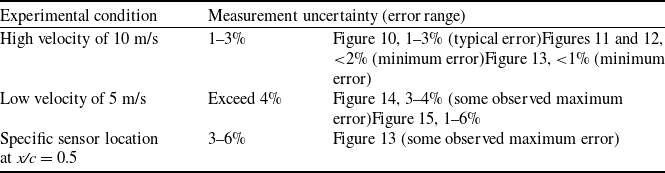
Determining the measurement error is essential for evaluating the accuracy of the obtained results. Generally speaking, the errors, caused by different sources, may be systematic or random. Our strategy in estimating the error is to distinguish between these types of errors. In the experiments, carried out in the wind tunnel, errors may be attributed to the unsteadiness inherent in the flow field and some fluctuations caused by measurement sources. While we conducted tests under the assumption of steady-state conditions, some fluctuations in sensor readings over the measurement intervals were observed. To ensure these fluctuations were indeed due to a source of measurement error and not an unsteady flow coming from the experiment, we repeated the tests under different situations. Our error percentages are calculated by analysing these fluctuations in the sensor readings. This analysis of the time-varying signal is our primary method for quantifying the measurement error. The obtained results illustrate that for the majority of wind tunnel tests, particularly at the high velocity of 10 m/s the measurement error of the aerodynamic coefficients typically falls in the range of 1–3%. Minimum errors were observed to be very small, often less than 2% (as shown in Figs 11–13). It should be noted that the static pressure sensors themselves have an inherent accuracy of 0.1% full scale (FS) error. The uncertainty in the free stream velocity (
 $V\infty $
) measurement is 0.1 m/s.
3.1.1 Conditions producing maximum errors
While typical errors are low, specific instances were observed, where error values exceeded 4% reaching a maximum range of 3–6%. These maximum errors were strictly limited to two experimental conditions:
-
1. Low free stream velocity (
$V\infty = 5\;{\rm{m}}/{\rm{s}}$
): At this lower speed, some error values exceeded 4%. This is primarily due to the increased relative contribution of fluctuations in the lower free stream. Since the plasma-induced momentum is more comparable to the freestream momentum at 5 m/s inherent flow unsteadiness contributes a higher percentage to the total measured signal fluctuation. -
2. Specific sensor location near x/c = 0.5: A localised peak in uncertainty was observed at a pressure sensor positioned approximately near the midpoint of the chord (x/c = 0.5). This sensor caused error bars in the range of 3–6%. This heightened uncertainty is attributed to the local influence of strong pressure gradients or heightened flow unsteadiness at this specific chordwise location.

The overall uncertainty in our wind tunnel measurements originates from several distinct sources (1) sensor accuracy: Including the precision of static pressure ports, differential pressure transducers and velocity measurement devices; (2) flow fluctuations: unsteadiness and turbulence inherent in the wind tunnel free stream; and (3) model manufacturing and placement tolerances: Systematic errors arising from slight deviations in the aerofoil geometry, the precise placement/alignment of the DBD actuator, and the resulting uncertainty in the effective angle-of-attack. The contributions of these sources were considered in calculation of the error, based on the relative error computation formula of the lift and surface pressure coefficients. A detailed classification of the estimated error ranges, observed for the lift and surface pressure coefficient measurements under various conditions, is given in the Table 1 below.
Summary of the measurement uncertainties under different experimental conditions

3.2 Aerodynamic model
A NACA0015 aerofoil with 15 cm chord length and 80 cm span, fabricated by a 3D printing method and PLA material, has been used as the aerodynamic model [Reference Mahdavi36]. In order to determine the static pressure, 27 pressure taps were distributed over the suction and pressure sides of the aerofoil, along the chord. A schematic picture of the aerofoil with the pressure taps, located on the aerofoil midspan and distributed over the lower and upper surfaces, is indicated in Fig. 4 (sensors at the trailing edge were covered by the electrodes). The lift coefficient is obtained by calculating the integral of the difference between the lower and upper surface pressure coefficients.
(a) A schematic picture of the aerofoil with the pressure points at the midspan of the airfoil distributed over the upper and lower surfaces.

4.0 Results and discussion (outside wind tunnel)
4.1 Discharge consumption power
The discharge consumption power is a substantial parameter to consider the plasma actuator as an efficient active flow control device. Hence, the performance of the actuator has been evaluated based on the electrical power consumption, in different literatures [Reference Benard10, Reference Debien17, Reference Moreau42]. There are two well-known methods to determine the electrical power; one is based on the electrical current measurement and the other one relies on the electrical charge computation.
Here, the time-averaged discharge consumption power of the normal jet was calculated using the applied voltages to the electrodes and the discharge current by equation (1), the following expression
 \begin{align} \bar P = 1/T\mathop \smallint \nolimits_{t = 0}^{t = T} \left| {V\left( t \right) \times i\left( t \right)} \right|dt \end{align}
where
 $V\left( t \right)$
is the measured instantaneous total applied voltage and
 $i\left( t \right)$
is the discharge conduction current. The discharge measured current was passing through the ground wire.
The applied voltage and total discharge current.

The instantaneous measured applied voltage and discharge conduction current.

As it is observed in Fig. 5, the discharge current is composed of two components: the conduction current, and the capacitive current. In order to determine the discharge consumption power, the sinusoidal capacitive current was removed from the total current as it is shown in Fig. 6. The obtained results reveal the appearance of microdischarges during positive and negative half-cycles of the applied voltage. Utilising Equation (1) illustrates that the discharge power equals 11 W in the steady operation mode, whereas for the unsteady actuation it decreases up to about 50 percent, approximating 5.6 W. Comparing two values of the discharge power clarifies the greater advantage of the unsteady excitation with respect to that of the steady one.
Velocity profile along the normal jet propagation at the centre of the electrode distance in the both (a) steady and (b) unsteady plasma operation modes.

 $Vy$
and
 $Vx$
velocity component of the induced jet, measured at points normal to the jet propagation at Y = 0 in the steady operation mode of the vertical jet.

(a) A schematic picture of the resultant vertical jet produced at the trailing edge over the pressure side of the aerofoil and (b) a schematic picture of the induced counter-flow in the floating configuration over the aerofoil.

Lift coefficient versus angles of attack (a) at pre-stall angles and (b) at post-stall angles of attack.

4.2 Electric wind velocity profiles
In a single SDBD plasma, a tangential jet flow is produced after the plasma ignition as the consequence of the interaction between the plasma accelerated charged particles and the ambient air. Measuring the velocity of this secondary flow is a well-established criterion for characterising the plasma actuator’s ability to impart momentum to the boundary layer. Studies have shown that when two SDBDs (similar to the configuration shown in Fig. 2(d)) are operated with equal applied high voltage amplitudes (
 ${V_1} = {V_2}$
), two tangential jets and several vortices are generated. As a result of their mixing, a vertical jet directed upward from the surface is produced [Reference Neretti43]. In this section, the velocity profiles, measured both along the resultant jet and normal to it will be discussed. Figure 7 illustrates the velocity profiles measured along the jet axis (y direction in Fig. 1) at x = 0 (referring to the centre of the electrodes distance) in the steady mode and at modulation frequencies of 127 and 423 Hz (the modulation frequencies were chosen based on unpublished experiments to measure wake vortex shedding frequencies). Additionally, it is important to note that due to the diameter of the glass tube, Y = 0 refers to Y = 0.5 mm above the dielectric surface. Measurements of the velocity profile along the jet propagation direction reveal the presence of reverse flow structures in both steady and unsteady modes, as illustrated by the Schlieren visualisation [Reference Neretti43, Reference Neretti45]. Furthermore, it is observed that the velocity values in steady operation mode are greater than those in the unsteady excitation. The figure highlights that even at 20 mm distance above the dielectric surface, a considerable value of the velocity is reached. Investigation of the velocity profiles of the normal jet and the corresponding profiles of a tangential single SDBD [Reference Benard and Moreau9] clarifies that using two opposite tangential jets will remove the limitation of the penetration depth of the wall-jet in the typical case. Based on the measurements, the highest velocities are consistently observed at distances of about 4–5 mm above the surface for both the steady mode and the 127 Hz modulation frequency. While a precise peak cannot be determined given the measurement uncertainty, the data clearly indicates a trend where the induced velocity is greatest in this region, gradually decreasing as the flow propagates away from the plasma source. One should note that the large shaded region observed in Fig. 7 are indeed due to the 500 Pa range of the transducer, with an accuracy of 0.1% FS (0.5 Pa), which is of the same order of magnitude as the dynamic pressure at velocities of 1–2 m/s, and makes the very low dynamic pressure measurement limited.
The x and y components of the velocity, measured normal to the jet propagation at Y = 0 at the steady state, are shown in Fig. 8. It can be observed that far from the centre of the electrode gap (X = 0), the values of
 ${V_x}$
are significantly greater than those of
 ${V_y}$
. Conversely, near the centre of the electrodes, the relationship is reversed, with
 ${V_y}$
becoming predominant. The results of both velocity components suggest the formation of a separation bubble due to the interaction of two vortices generated by each SDBD near the surface. This phenomenon has been corroborated by the visualisation of jet development [Reference Neretti43, Reference Neretti45].
5.0 Results and discussion (wind tunnel experiments)
Wind tunnel experiments were conducted on a NACA0015 aerofoil at two Reynolds numbers of
 $52,791$
and
 $105,582$
correspond to the free stream velocities of 5 and 10 m/s, respectively. We employed low Reynolds numbers since our study primarily focuses on advancing fundamental understanding and exploring the capabilities of DBD flow control, we acknowledge the importance of specifying potential applications. Notably, our research aims to contribute to an evaluation of the DBD plasma actuator’s authority, particularly as a trailing edge flow control device such as Gurney flaps. These studies typically operate within Reynolds number ranges similar to ours [Reference Feng20, Reference Feng21]. The SDBD configuration, which is capable of generating a vertical jet, is schematically illustrated in Fig. 9. It was positioned at the trailing edge of the pressure side to evaluate its performance as a virtual flap. In this investigation, the aerodynamic operation of a vertical jet, similar to a mechanical Gurney flap, is compared with that of a counter flow wall jet, produced in a floating structure (see Fig. 2c). The geometrical characteristics of the SDBD was explained in section 2.1. The experiments are focused on the flow control authority of the normal jet with respect to that of the single jet. The investigations were carried out by means of measuring the surface pressure distributions and the lift coefficient computation of the aerofoil at some pre-stall and post-stall angles of attack. The operation of the plasma-induced jets at the trailing edge were assessed under the plasma excitation in both steady and unsteady modes. The obtained results will be discussed at the following subsections.
5.1 Flow control results in the velocity of 10 m/s
Manipulating flow over the aerofoils at stall and post-stall angles of attack has attracted great attention to improve the aerodynamic efficiency of the aerofoils. Hence, the modifications of the aerodynamic characteristics under the effect of plasma actuators have been studied in different literatures [Reference Meng39, Reference Thomas56, Reference Wang59]. In this section, we explain the results of the surface pressure measurements and the lift coefficient computations of the aerofoil by applying two configurations of SDBD plasma, floating and double-SDBD, at the trailing edge. The measurements were performed in the free stream velocity of 10 m/s and the SDBD plasma was actuated in both steady and unsteady modes. All the experiments were conducted at DC = 50%, sinusoidal frequency of 5.5 kHz and applied voltages of
 $17{\rm{k}}{{\rm{V}}_{{\rm{pp}}}}$
to the upper electrodes. The unsteady investigations at pre-stall angles of attack were conducted at frequencies of 127 and 423 Hz and based on the obtained results the frequency of the modulated signal was selected for the post-stall angles of attack measurements. The lift coefficient of the aerofoil at some pre-stall and post-stall angles of attack is depicted in Fig. 10(a) and (b). Considering the values of the lift coefficient reveals that the maximum lift coefficient (
 $C{l_{{\rm{max}}}}$
) is reached at
 $\alpha = 5^\circ $
while it decreases substantially at higher angles of attack.
As it is observed, the most significant enhancement in the lift coefficient (relative to plasma off) at pre-stall angles of attack – approximately 15% – is achieved by the floating structure at a modulation frequency of 127 Hz at
 $\alpha = 3^\circ $
. For the vertical jet flow of the double-SDBD configuration, although no lift improvement is observed in the steady operation mode at small angles of attack, there is an increase of about 8% in lift during unsteady actuation at 127 Hz. Given that the normal jet at 423 Hz shows no efficiency at pre-stall angles of attack, the effectiveness of the unsteady normal jet at this frequency was subsequently assessed at higher angles of attack. The non-zero lift coefficient for the unactuated case at zero degrees angle-of-attack is likely due to minor imperfections from the actuator installation, slight inaccuracies in the angle-of-attack fixing system, and inherent measurement uncertainties. However, since the experimental setup remains consistent across all cases, this baseline offset does not impact the comparative findings. The key result is the significant and repeatable change in lift coefficient produced by the plasma jet itself. The obtained results indicate that at high angles of attack, the aerodynamic performance of the induced normal flow, in both steady and unsteady modes, increases considerably. As shown in Fig. 8(b), the modulated vertical jet at a frequency of 423 Hz, which exhibited low performance at pre-stall angles, effectively enhances lift at post-stall angles of attack, achieving improvements of approximately 11% and 38% at
 $\alpha = 12$
and
 $\alpha = 14$
, respectively. This phenomenon can be explained by the mechanisms of plasma operation at different angles of attack. At high angles, flow separation occurs, resulting in the formation of reverse flow structures. Experimental investigations have shown that vortex flow structures induced by SDBD plasma can effectively control flow separation at high angles of attack due to their interaction with the natural instabilities of the base flow [Reference Abdollahzadeh1, Reference Durbin and Reif18]. In the case of the vertical jet, generated in configuration shown in Fig. 2(d), Krishnan et al. demonstrated that operation of the normal flow in unsteady mode in quiescent air produces multiple counter-rotating vortex pairs [Reference Santhanakrishnan54]. Therefore, it can be concluded that the enhanced flow control capability of the unsteady normal jet at high angles of attack is attributed to the interaction of the induced jet vortices with the reverse flow structures of the main flow, resulting in an increase in the lift coefficient. At these conditions, where considerable flow separation occurs, the unsteady jet’s induced vortices introduce high-momentum fluid into the separated boundary layer, promoting a local reattachment. This reattachment effectively alters the pressure distribution on the upper surface, creating an effect analogous to a virtual camber increase at the trailing edge, which substantially reduces the size of the separated region and increases lift. Another perspective can be offered regarding the behaviour at small angles of attack, where separation does not occur and the flow remains attached to the bottom surface of the aerofoil. In this regime, there is a direct interaction between the main flow and the plasma induced normal flow, which results in the normal jet deflecting and deviating from the operation of a virtual Gurney flap at the trailing. However, at higher angles of attack, as flow separation occurs, this effect diminishes, and the vertical jet behaves more like a mechanical Gurney flap. This transition may account for the observed increase in lift coefficient even in the steady mode.
5.1.1 Surface pressure measurements
For more discussion about the influence of the SDBD plasma jets on the aerodynamic characteristics of the aerofoil, surface pressure measurements were carried out. Figure 11a and b indicate the lower surface pressure (
 $C{p_{lower}})$
distribution over the chord of the aerofoil. It is observed that the plasma-induced flow has an insignificant effect on the bottom surface pressure. In this situation, there is no evidence of the flow separation over the lower pressure regions; therefore, the application of SDBD plasma does not produce any noticeable influence on the pressure distribution. The relatively high pressure of the flow on the lower surface may contribute to this outcome, as studies have indicated that the effectiveness of plasma actuators in altering pressure distribution can be diminished under conditions of high surface pressure. In this regard, Moreau et al. found that while DBD actuators can enhance lift and modify flow characteristics, their impact is less pronounced in regimes where the flow remains attached and experiences higher pressures [Reference Moreau42]. Furthermore, Zhang et al. demonstrated that plasma-induced flow structures can be less effective in modifying pressure distribution when the baseline flow is already well-structured and high-pressure dominated, leading to limited interaction with the plasma-induced flow [Reference Im29]. These findings suggest that the higher pressure in the lower surface flow may indeed be a reason for the limited effect of DBD plasma on the pressure distribution at pre-stall angles of attack. In the case of a normal jet, where
 $V{1_{applied}} = V{2_{applied}}$
, the intensity of two counter-jets is equal and their power is also balanced. Indeed, the induced jet from the plasma actuator (SDBD2) tends to increase pressure due to the counter-flow it creates. In contrast, the co-flow jet generated by the other actuator (SDBD1) works against this effect by reducing pressure. As a result of this interaction, the overall pressure recovery over the lower surface of the aerofoil is limited. However, at higher angles of attack (
 $\alpha = 12^\circ {\rm{\;and\;}}14^\circ $
, as it is shown in Fig 12(a) and (b)), both the vectorised and floating plasma jets become significantly more effective, particularly near the trailing edge of the aerofoil. At these angles, the application of the plasma actuators leads to an increase in the lower surface pressure, even at the frequency of 423 Hz, observed across the entire length of the aerofoil’s chord. A comparison of the pressure coefficient (
 $Cp$
) values across different experimental conditions reveals that the observed variations exceed the estimated measurement error, which is between 1–3%. For instance, at several key positions along the chord (X/C = 0.3, 0.5, 0.7), the differences in
 $Cp$
between parameter sets (such as different frequencies and plasma states) consistently surpass 10% of the
 $Cp$
values. This is significantly larger than the expected measurement error, indicating that the variations in
 $Cp$
are not random noise but instead reflect real physical changes due to the altered test conditions. Consequently, it can be concluded that the changes observed in the lower surface pressure distribution are attributable to the modifications in experimental parameters rather than measurement uncertainty.
Surface pressure measurements over the lower surface in the velocity of 10 m/s (a) at
 $\alpha = 3^\circ $
and (b)
 $\alpha = 5^\circ $
.

Surface pressure measurements over the lower surface in the velocity of 10 m/s (a) at
 $\alpha = 12^\circ $
and (b)
 $\alpha = 14^\circ $
.

There is a different scenario for the case of high angles of attack, which is not solely based on the strength of the resultant jet. As mentioned before, at post-stall angles of attack, flow separation predominantly occurs on the upper surface, while the lower surface remains largely attached, as evidenced by our graph. The rotational flow near the trailing edge plays a critical role here. This reversed flow can extend from the upper surface, roll around the trailing edge, and interact with the lower surface, creating a complex flow field. The additional pressure gradient created by this rotating flow can facilitate the interaction of plasma actuators with the lower surface flow. The results obtained in Fig. 12 verify this idea, as the unsteady actuation of both floating and vectorised jet SDBD configurations leads to a significant increase in suction pressure on the lower surface, particularly near the trailing edge. This observed increase in negative
 ${C_P}$
is a direct result of the additional pressure gradient created by the rotating flow. In the unsteady mode, the mechanism of plasma flow control is defined not only by the momentum injection to the boundary layer but also by the propagation of discrete vortex structures downstream from the plasma generation region. This implies that plasma-induced flow becomes more effective under these conditions, helping to stabilise the boundary layer and keep the flow attached for longer, thereby reducing drag and improving performance, even though the upper surface flow is mostly separated. These findings underscore the effectiveness of plasma actuation on the lower surface at high angles of attack, where the influence of the rotational flow and lower pressure conditions enhances overall aerodynamic performance.
Surface pressure measurements over the upper surface in the velocity of 10 m/s (a) at
 $\alpha = 12^\circ $
and (b)
 $\alpha = 16^\circ $
.

The upper surface pressure coefficient (
 $C{p_{upper}})$
at
 $\alpha = 12^\circ,{\rm{\;}}16^\circ $
is depicted in Fig. 13. Evaluating the
 $C{p_{upper}}$
coefficient at post-stall angles of attack demonstrates that there is an area of the increased velocity near the leading edge, while a sudden reduction of the velocity is realised at points
 $x/c = 0.33 - 0.4$
. This implies the occurrence of the flow separation over the aerofoil and formation of the revers flows at the second half of the chord to the trailing edge. The actuation of both plasma configurations, particularly the floating structure, enhances the amplification of vortex structures at the trailing edge, akin to the effect of a mechanical Gurney flap. This effect is especially pronounced at a higher angle-of-attack (α = 16°), where the floating and vertical plasma-induced jets effectively reduce the upper surface pressure coefficient.
5.2 flow control results in the velocity of 5 m/s
Figure 14 exhibits the lift coefficient of the aerofoil at the pre-stall and post-stall angles of attack in the free stream velocity of 5 m/s. It is observed that the lift coefficient of the aerofoil reaches its maximum value at
 $\alpha = 5^\circ $
and it decreases substantially at
 $\alpha = 9^\circ $
. Thereafter, at higher angles of attack it nearly plateaus. Generally, according to the literatures the NACA 0015 aerofoil stalls at
 $13^\circ \le \alpha \le 15^\circ $
at Reynolds numbers in the order of
 ${10^5} - {10^6}$
[Reference Jukes and Choi30, Reference Zaki63, Reference Zanon64], while at lower Reynolds number of
 ${10^5}$
it has been occurred at smaller angles of attack
 $6^\circ \le \alpha \lt 10^\circ $
[Reference Abdullah2, Reference Akansu4]. Since the arrangement of the electrodes over the surface may hasten the stall compare to the clean one [Reference Messanelli and Belan40, Reference Pouryoussefi46, Reference Pouryoussefi47], the stall of the aerofoil at lower Reynolds number probably happens at an angle-of-attack between
 $\alpha = 5^\circ $
and
 $\alpha = 9^\circ $
in our case of study at the Reynolds number of
 $52,791$
. It is clearly inferred from the obtained results that at small angle-of-attack, the induced jet of the floating structure shows the highest efficiency in increasing the lift coefficient, particularly in the steady operation mode. It is observed that a considerable improvement of the maximum lift coefficient about 26% is reached by ignition of the steady floating jet at
 $\alpha = 5^\circ $
with respect to the flow without plasma effect. However, the flow control authority of the vertical jet in the double-SDBD configuration becomes particularly significant at high angles of attack, where the flow is fully separated from the trailing edge. At this situation, the aerodynamic operation of the vertical jet is comparable with the single wall-jet such that a lift coefficient increases about 23% is realised at
 $\alpha = 12^\circ $
, which is 5% greater than that of the unsteady floating jet. Moreover, it must be noted that at high angles of attack, the operation of the SDBD plasma jet in the unsteady mode differs significantly from that of the steady one, indicates the great flow control potential of the unsteady actuation at high angles of attack, which can be more discussed by the surface pressure distribution measurements.
Lift coefficient versus angle-of-attack in the velocity of 5 m/s at some pre-stall and post-stall angles of attack.

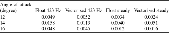
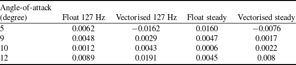
Comparing the results in Fig. 14 with the lift coefficient at a velocity of 10 m/s reveals a significant difference in performance between the steady and unsteady jets at a lower velocity of 5 m/s, where the steady jet outperforms the unsteady jet. However, as the velocity increases, the unsteady excitation of both the counter-flow and normal jets demonstrates improved performance in lift coefficient enhancement, even at pre-stall angles of attack, compared to the steady jet. This improvement can be attributed to the differing mechanisms of plasma interaction with the main flow. Measurements of plasma-induced flow velocity indicate that the steady jet generates higher velocity values than the unsteady jet. Consequently, at lower Reynolds numbers, the steady jet’s velocity becomes comparable to the free stream velocity, resulting in a more substantial effect on the flow. However, at higher velocities, the significance of this effect diminishes, and the characteristics of the unsteady jet in generating vortical flow structures also contribute to its performance. To quantify the performance of different configurations of plasma excitation modes, the parameter,
 $\frac{{\Delta {C_L}}}{P}$
, was considered. Tables 2–4 indicate the values of this parameter in the free stream velocities of 5 and 10 m/s, where
 $\Delta {C_L}$
represents the difference between the
 ${C_L}$
values of plasma on and plasma off cases and
 $P$
is the discharge power. As presented in the Tables 2 and 3, at higher velocity of 10 m/s, the unsteady plasma mode at both configurations, exhibits higher efficiency than the steady one. In contrast, the values of the parameter for the steady plasma excitation correspond to improved performance at small angles and lower velocity. Moreover, the negative values illustrate the inefficiency of the plasma excitation in increasing the lift coefficient.
Values of
 $\frac{{\Delta {C_L}}}{P}$
in
 $V = 10{\rm{\;m}}/{\rm{s}}$
for different plasma excitation modes at pre-stall angles of attack

Values of
 $\frac{{\Delta {C_L}}}{P}$
in
 $V = 10{\rm{\;m}}/{\rm{s}}$
for different plasma excitation modes at post-stall angles of attack

Values of
 $\frac{{\Delta {C_L}}}{P}$
in
 $V = 5{\rm{\;m}}/{\rm{s}}$
for different plasma excitation modes and angles of attack

5.2.1 Surface pressure measurements
The surface pressure distributions over the lower and upper surfaces of the aerofoil were measured to find out the aerodynamic changes resulting from the presence of the plasma. The bottom surface pressure distribution at
 $\alpha = 5^\circ $
(see Fig. 15(a)) reveals more efficiency of the single jet in enhancing the pressure than an increased velocity of 10 m/s such that a considerable enhancement of the lower surface pressure is obtained in the steady mode. This is especially evident near the location of the plasma actuator, confirming that the value of the plasma induced-momentum relative to the free stream velocity contributes positively to performance. At a higher angle-of-attack (α = 10°), the flow on the upper surface experiences significant separation, while the lower surface remains unaffected by separation. In this context, a notable increase in lower surface pressure is observed, primarily attributed to the unsteady operation of both the single and normal plasma jets (see Fig. 15(b)). The interaction between these jets and the reversed flow generated near the trailing edge enhances the pressure recovery on the lower surface. This allows the plasma actuators to effectively stabilise the boundary layer, thereby improving overall aerodynamic performance even as the upper surface flow becomes detached. At higher angles of attack, a more powerful flow near the trailing edge interacts with the lower surface, creating a significant pressure gradient. This interaction enhances the effectiveness of plasma actuators on the lower surface, as the additional vertical flow contributes to a lower pressure environment. Consequently, this alteration in pressure influences Kutta’s condition, leading to a modification in the balance of flow around the upper surface, particularly near the leading edge. Thus, the interaction of the plasma with the altered flow dynamics at higher angles of attack enhances overall aerodynamic performance. For the case of upper surface pressure, shown in Fig. 16, the results of the measurements illustrate that at small angle-of-attack the vertical jet is unable to reduce the pressure and only the steady and unsteady jets of the floating structure affect the pressure, mostly at first half of the chord (
 $x/c = 0 - 0.6$
).
Lower surface pressure measurements in the velocity of 5m/s (a) at
 $\alpha = 5^\circ $
and (b)
 $\alpha = 10^\circ $
.

Surface pressure measurements over the upper surface in the velocity of 5 m/s at
 $\alpha = 5^\circ $
.

6.0 Conclusions
In the present paper, the effect of an SDBD () plasma in a three-electrode configuration, acting as a virtual flap, on the flow control over a NACA 0015 aerofoil was investigated experimentally. The experiments were conducted in the free stream velocities of 10 and 5 m/s by applying the SDBD in two arrangements of floating and double-SDBD, capable of producing a single wall-jet and a net vertical flow, respectively. In order to determine some characteristics of the SDBD plasma, mechanical and electrical measurements were performed in the still air. The velocity profile measurement along the normal flow reveals the formation of the vortical structures in the steady and unsteady plasma operation modes near the surface at the centre of the electrode distance, which can be of great importance in manipulating the main flow. It was also found that applying the vertical flow leads to a greater penetration depth of the plasma-induced flow to affect the flow with respect to the typical single wall-jet. In order to assess the flow control authority of two plasma actuator structures, further investigations were carried out in a low-speed wind tunnel. Some of the most important results are as follows:
-
• It was clarified that although the steady counter-flow demonstrates high aerodynamic performance at low velocities, the unsteady actuation of both the single and vertical flows results in a greater enhancement of the lift coefficient compared to the steady one at an increased velocity of 10 m/s. At higher velocities, the unsteady jet’s periodic, high-energy vortices are able to penetrate and mix with the faster-moving boundary layer more effectively than a steady, low-momentum jet and are better suited to actively manage the higher-momentum flow.
-
• It was observed that while the vertical flow operating at a frequency of 423 Hz does not yield a considerable improvement in the lift, its operation at a frequency of 127 Hz results in an 8% enhancement in the lift coefficient at an angle-of-attack (α) of 3 degrees.
-
• Comparing the lift coefficients in different velocities shows that the vertical jet demonstrates significantly improved aerodynamic performance at high angles of attack. Specifically, the unsteady vertical jet achieved enhancements of approximately 23% and 38% in lift coefficients at angles of attack of α = 12° and α = 14°, respectively, for free stream velocities of 5 and 10 m/s.
-
• Increasing the free stream velocity significantly enhances the operation of the vertical jet, which is actuated at a certain low modulation frequency, even at pre-stall angles of attack. This improvement in the lift coefficient is particularly noteworthy as it highlights the interaction between velocity and angle.
-
• The results of the surface pressure measurements indicate that at a low velocity of 5 m/s, the single counter-flow wall-jet enhances the lift coefficient by increasing the lower surface pressure. At a higher velocity of 10 m/s and at high angles of attack, both plasma configurations, particularly in the steady mode, function similarly to a Gurney flap. They enhance lift by amplifying the vortical structures at the trailing edge and increasing the lower surface pressure, especially in the unsteady excitation mode.
-
• Evaluating the aerodynamic results of the single counter-flow of the floating structure illustrated that it represents the most efficiency in improving the lift coefficient at small angles of attack and due to the requirement of just one powered electrode, it can be considered as a desirable configuration.
The primary objective of introducing a normal jet at the trailing edge of the aerofoil was to explore its functionality as a virtual flap. Experimental results indicated that the vertical jet effectively behaves like a flap, particularly at post-stall angles of attack and during unsteady actuation. Hence, studying the aerodynamic efficiency of the modulated vertical jet as a virtual flap at higher angles of attack at higher Reynolds number is proposed for the future works.
Competing interests
The authors declare none.