I. INTRODUCTION
The ASTM defines additive manufacturing (AM) as the “process of joining materials to make objects from 3D model data, usually layer upon layer, as opposed to subtractive manufacturing methodologies.” 1 This group of processes has experienced an exponential development during the last decade. The continuous improvement in AM capabilities and the introduction of new techniques have expanded the range of applications from merely rapid prototyping issues to direct manufacturing of tools and functional parts. Although material behavior is actually affected by building procedure and process configuration, the layer-upon-layer nature of AM parts could influence mechanical properties and cause nonisotropic behavior. Moreover, this behavior could not only be related to the specific characteristics of material deposition within each single layer, but also to the way in which the layers are stacked and bonded.
Nonisotropic mechanical behavior of AM parts has been previously studied by some authors. In fused deposition modeling (FDM), orthotropic behavior of parts has been highlighted. Reference Bellini and Güçeri2 Moreover, axial orientations of ABS FDM parts, with the fibers deposited in planes parallel to the applied force, provide higher values for the compressive strength than transverse orientations, with the fibers deposited in planes orthogonal to the applied force. Reference Ahm, Montero, Odell, Roundy and Wright3 Similar behavior shall be expected in other processes like nanocomposite deposition, where differences for the compressive strength values up to 23.6% regarding on built direction have been found. Reference Lee, Kim, Kim and Ahn4 Also in laser sintering of rubber-like materials, anisotropic characteristics have pointed out that horizontal built orientation results in an improved mechanical behavior. Reference Soe, Martindale, Constantinou and Robinson5 Nevertheless, processes like 3D printing are expected to provide maximum values for nonorthogonal directions, when fibers are oriented following a 45° sloped plane to the applied force. Reference Lee, Kim, Kim and Ahn4
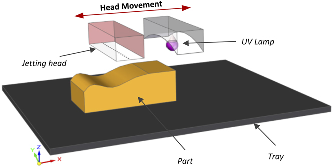
The present work focuses on PolyJet 3D AM technology. This process consists of jetting layers of an acrylic-based photopolymer on a flat surface. After each jetting cycle, the layer is cured with UV radiation, so that the material solidifies and additional layers can be subsequently stacked in the Z direction. Reference Zeytoun, Levi, Kritchman, Eshed, Gothait, Danal, Bar Nathan, Kleinhendler and Menchink6 An array of injection orifices (also known as injection block or printing head), capable of independently dispensing certain amounts of material, is used for jetting the photopolymer. The relative disposition of such elements alongside with the base tray and a generic part geometry can be seen in Fig. 1.
Scheme of the main elements involved in the PolyJet process.
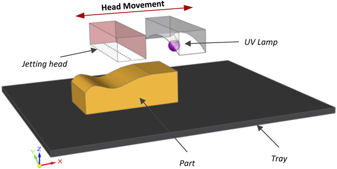
A leveling roller is simultaneously used to level the jetted material to a predefined layer height by removing surplus material. Thus, each layer consists of precisely defined regions of model and/or support material. Since the injection block moves back-and-forth along one axis while dispensing the material and performing the UV curing, the geometry of each layer could be assimilated to a series of parallel fibers. Some recent investigations have dealt with the analyses of mechanical properties of PolyJet manufactured parts.
The tensile and flexural properties of various materials have been evaluated and the results show that slight differences with respect to reference values, as provided by the manufacturer, were obtained. Reference Pilipović, Raos and Šercer7 On the other hand, a dependence of the tensile strength and elongation at failure with part orientation within the coordinate planes of the machine has been observed. Reference Kesy and Kotlinski8 Several works have also pointed out the relationship between nonuniform UV curing and mechanical properties of PolyJet parts. Thus, nonuniform exposition related to part geometry Reference Kesy and Kotlinski8 and over-curing caused by parts distribution within the tray Reference Barclift and Williams9 are among the aspects to be aware of. These results are consistent with studies on stereolithography parts characterization, where the UV exposure time is widely accepted as the main parameter affecting the final material strength. Reference Jacobs10 It is also known that increasing UV energy shall lead to a higher degree of polymerization and cross-linking density of the material. Reference Zabti11 This is an important feature, since this effect has influence on the glass transition temperature of the cured material and, therefore, in the final properties. Consequently, material behavior could be toward the viscoelastic or rubbery material domain at relatively low temperatures. Reference Lovell and Bowman12 Since curing could be affecting the material properties and raw materials used in the PolyJet process present relatively low glass transition temperatures (close to 50 °C), a viscoelastic behavior should be expected at normal ambient temperatures. Reference Ferry13,Reference Lakes14 This implies that, in standard tensile tests, the influence of the strain rate applied to the specimen should be taken into account. On the other hand, the experimentation related to anisotropic behavior of AM parts uses mainly orthogonal orientations along the X, Y, or Z axis, with very few works considering 45° orientations in XY, YZ, or XZ planes. Consequently, the variability of mechanical properties in parts manufactured with the PolyJet process under different angular orientations has not been yet deeply analyzed.
In this article, these two aspects have been taken into account, so a study of the viscoelastic behavior of the acrylic material PolyJet RGD240 is presented in which the slope (B) of the surface with respect to the Y axis has been considered as a possible source of nonisotropic behavior (see Fig. 1 for axis orientation). The relaxation modulus E(t) has been used as characterization parameter for the viscoelastic behavior, while the angular orientation of the part with respect to Y(B) has been selected as representative of surface slope.
II. EXPERIMENTAL PROGRAM
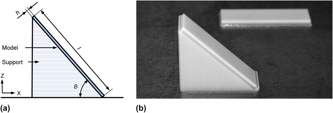
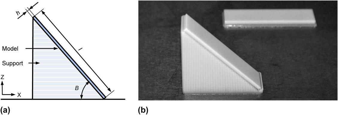
A test bar with a nominal thickness h of 2 mm, a width w of 12 mm, and a length l of 50 mm has been selected for test purposes. Figure 2(a) represents the parameterization of a tilted specimen, while Fig. 2(b) provides an image of two parts (B45° and B0°) just finished on the tray.
Test specimen geometry: (a) Dimensional and slope (B) parameterization and (b) Detailed view of 45° and 0° sloped parts on the manufacturing tray.
A Stratasys Object 30 machine has been used for manufacturing test specimens. Model material is a Stratasys RGD240 photopolymer, while support material is a Stratasys FullCure 705 photopolymer. Layer thickness for this material is 28 µm. Resolution in both X and Y directions is up to 600 dpi (approximately 42 µm). This particular machine has two printing heads, with independent injection orifices. Specimen geometry has been designed using Solid Edge CAD software and then converted to Standard Tessellation Language (STL) format using a 0.001 mm conversion tolerance. Thereafter, STL files were incorporated to the Stratasys proprietary software and properly oriented, so that, a tray model containing the predefined orientations was constructed and processed. Due to the slope, additional support material has to be placed under model geometry to provide proper stability for new layers. This support volume is automatically defined by Stratasys software so that support material is added to fill the space within the model and its projection onto the XY plane. The upper surface is free of support and adopts a “glossy” finish. Then, the complete volume formed by both model and support material is sliced into layers.
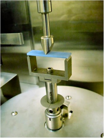
A RSA3 Dynamic Mechanical Analyser (TA Instruments) has been used to evaluate E(t). This equipment uses an independent drive motor capable of applying either static or oscillating loads. These loads are instantaneously registered with a load cell. This device is also equipped with a temperature-controlled chamber, so that experiments could be conducted over a wide range of temperatures (from −60 °C to 150 °C). In present experimentation, all tests were conducted using a three-point bending tool under controlled laboratory temperature (20 °C ± 0.5). Figure 3 shows an example of a 3-point bending test, where the tested specimen and its spatial disposition can be clearly seen. The specific level of strain (0.1%) was produced under an instantaneous strain step, and was kept constant during the stress relaxation test. Loads were measured at carefully timed intervals under the specified constant strain and then stress was calculated by considering each test specimen actual dimensions. Finally, relaxation modulus was obtained using Eq. 1.
 $$E(t) = {{\sigma (t)} \mathord{\left/ {\vphantom {{\sigma (t)} {{\varepsilon _0}}}} \right. \kern-\nulldelimiterspace} {{\varepsilon _0}}}\quad .$$
Example of a 3-point bending test.

III. RESULTS AND DISCUSSION
The experimental design has been divided into two stages: first, a comparative analysis of influence factors was carried out; then, an in-depth characterization of E(t) dependences was performed.
A. Comparative analysis of influence factors
During the first stage, a 32 full factorial design of experiments has been used for evaluating relative influence of two factors: time (t) and slope (B), upon the response E(t). The objective of this stage was to establish whether clear viscoelastic behavior could be observed. Simultaneously, possible influence of surface slope and the cross-influence between these factors were also analyzed. With this purpose, few experiments with short-timed measurements were planned, and three levels were chosen for both t (0.5 s, 5.5 s, and 10.5 s) and B (0°, 45°, and 90°). Three specimens matching these slopes were manufactured in three different trays. Each specimen has been tested with the DMA-RSA3 five times to include variability due to measurement conditions and experimental runs were blocked for each tray. Accordingly, the analysis is based on 135 values. The statistical analysis has been performed using Minitab 16.1.1.
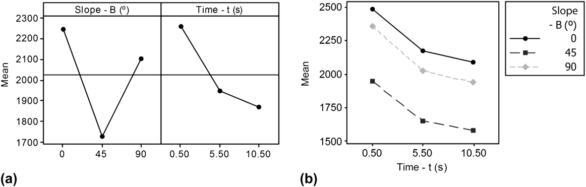
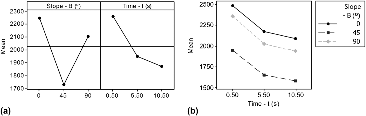
The analysis of main effects plot [Fig. 4(a)] and interaction plot [Fig. 4(b)] provides a clear idea of each factor influence. Taking note of main effects, results show that both t and B factors are significant. This result implies that mechanical properties for PolyJet manufactured parts are both time and orientation dependent. Distribution of means regarding t indicates a clear viscoelastic behavior, with E(t) values decreasing with time. Orientation of surface has also great influence upon E(t), providing a minimum value for the 45° slope and a maximum for the horizontal (0°) parts. Vertical parts (90°) reveal an intermediate behavior, with relatively high values of E(t). On the other hand, interaction plot, Fig. 4(b), contains parallel lines representing the evolution of E(t) for different slopes, which indicates that t and B do not present any interaction. According to this, both factors have an independent influence upon E(t) and could be independently described.
Analysis of influence factors: (a) Main effects plot and (b) Interaction plot for E(t).
Although results indicate that a relaxation effect should be expected, experimental tests only cover a limited time range of 10.5 s. Then, additional long-term measurements should be obtained to properly characterize the relaxation behavior. In a similar way, results indicate that the evolution of E(t) regarding slope does not follow a linear pattern, but presents an unexpected minimum value for an intermediate slope. Thus, it seems clear that more-specific in-depth analysis should be performed to fully describe slope-dependence of material properties.
B. Characterization of E(t) dependences
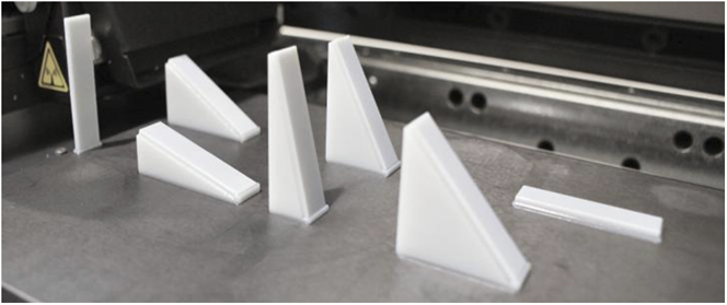
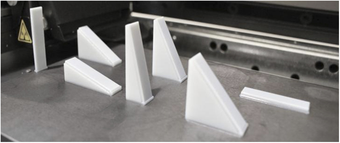
A new set of tests were conducted to improve the characterization of time-dependence and slope-dependence behavior. Four additional trays containing seven orientations (0°, 15°, 30°, 45°, 60°, 75°, and 90°) were constructed and the resulting specimens were measured. The location within the tray for the new oriented specimens is shown in Fig. 5.
Relative location of test specimens within the tray.
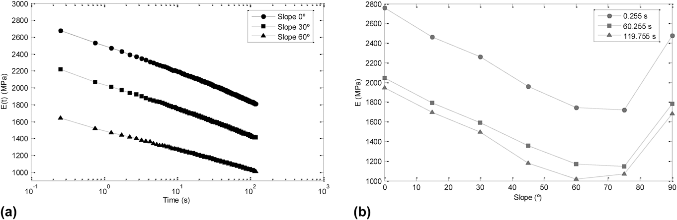
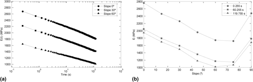
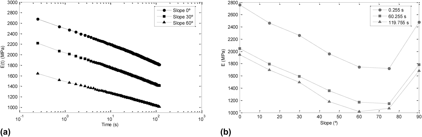
The new specimens were tested for an extended period of 120 s (0.1% strain) and the relaxation modulus was calculated to obtain a long-term description of the viscoelastic behavior. A sampling ratio of 2 Hz was used. Each tray of specimens was tested twice in different consecutive days. Results do confirm time-dependence behavior, so material properties should be considered more close to the viscoelastic domain rather than to a linear-elastic domain. Even when slope shows no interaction with relaxation in mechanical properties, it is remarkable that a similar decrease in the Young's modulus was observed for all the tested specimens. A graphical representation of these results is provided in Fig. 6(a), where the curves obtained for 0°, 30°, and 60° sloped parts coming for one particular tray are presented.
(a) Evolution of E regarding time and (b) Evolution of E regarding slope.
Since similar results were obtained for all combinations of trays and parts within the experimentation, this behavior can be accepted as material-and-process related. Average
 $\left( {{{\bar \Delta }_{E(120)}}} \right)$
and standard deviation (σ
E(120)) values have been calculated for the perceptual difference between E(0) and E(120) with respect to E(0) for all tested B levels, by measuring twice each one of the five replicas manufactured for each specimen. Results can be found in Table I.
Values for
 ${\bar \Delta _{E(120)}}$
and σ
E(120) for tested B levels.
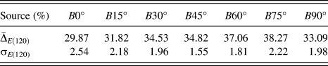
According to these results (see Table I) an approximately minimum 29.87% E(t) reduction must be expected after 2 min of loading, whereas this relaxation in mechanical properties could reach a 38.27% maximum for 75° sloped surfaces. This behavior is consistent through the experimentation, as values lower than 2.54% are expected for the standard deviation.
The analysis of E(t) results for different slope values obtained for equal periods of time [Fig. 6(b)] confirms the conclusions of the initial comparative analysis and provides a more-detailed description of its dependence. Therefore, the relaxation modulus decreases as slope increases from 0° up to 60°. This tendency is characteristic of orthotropic materials, such as laminated and fiber-oriented composites or wood. Then, 75° sloped parts present results for E(t) that are similar to those obtained for 60° slopes. Finally, E(t) values suddenly increase for 90° sloped parts, reaching values similar to those obtained for 15° sloped parts. This means that a significantly higher stiffness shall be expected for such oriented parts. Nevertheless, this result is not consistent with the orthotropic behavior mentioned above, since the modulus should decrease permanently or at least remain nearly unchanged when the layers or fibers angles are close to be parallel to the load in a bending test.
Two considerations have to be introduced at this point: firstly, reduction in material properties falls to a nearly stabilized value and only close-to-vertical parts present locally higher stiffness; secondly, this result could be considered unexpected according to PolyJet construction procedure, since each jetted layer has to be cured before next layer is added to the part. This suggests that the resultant parts should constitute, in one way, a laminated material. Assuming this premise, a slightly lower E(t) value should be expected for the 90° sloped part in comparison with precedent slopes, since vertical parts have their cured layers parallel to the applied load direction. Thus, whereas an orthotropic-like behavior is observed up to 75° slope, an additional noncontrolled phenomenon should be affecting 90° sloped parts.
Several hypotheses like differences in temperature gradient were considered and rejected at this point. However, 90° sloped parts are self-supported, and do not require of additional support material covering their lateral sides. This characteristic is unique within the experimental range, as other orientations require support material bellow one of the lateral sides of the part to be stable. This had led to consider the possibility of support material affecting homogeneous curing of photopolymer. Since previous studies have evidenced that an increase in UV exposure time produces a hardening effect in parts produced by photopolymerization, Reference Barclift and Williams9–Reference Zabti11 it is possible that support material is introducing some kind of shielding effect. If this is the case, a reduction in total UV energy reaching zones of the part would surely provoke a local reduction in curing and a reduction in material properties. Accordingly, nonsupported 90° sloped parts should not be experiencing abnormal reduction in UV exposure, which could explain why this orientation provides relatively higher stiffness.
C. Evaluation of support material shielding effect upon UV curing
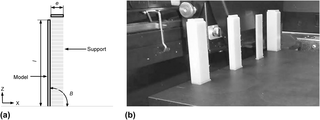
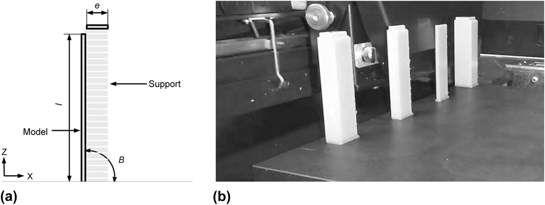
Four alternatively designed 90° parts were constructed and tested to evaluate the possible incidence of this phenomenon upon the 90° sloped specimen. A disconnected horizontal component was placed with a slight separation at the top of the part, so that the software was forced to apply additional support material. This component was used to artificially introduce a shielding effect, since the vertical layer of support material should reduce the amount of UV energy affecting one of the larger surfaces of the part. The so-designed part has initially the shape of an inverted “L”, but later the top component shall be removed alongside with support material and the final specimens have the same geometry that was previously tested. To introduce the possibility of support thickness as an additional factor influencing the amount of UV energy that reaches the surface, four different values for the support thicknesses (e) have been considered: 0, 2, 5, and 10 mm. Since 0 mm thickness specimen does not require additional support material, it is expected to deserve similar results that previously tested 90° sloped surfaces. On the other hand, a certain reduction in E(t) is expected to be found for the 2 mm support thickness part, and this reduction should be greater for the 5 mm and 10 mm parts. Figure 7(a) represents the parameterization of this new specimen, while Fig. 7(b) provides an image with parts manufactured with different thickness values.
Test specimen geometry: (a) Parameterization of specimens with additional support for testing shielding effects and (b) Detailed view of 90° sloped parts with different support thicknesses.
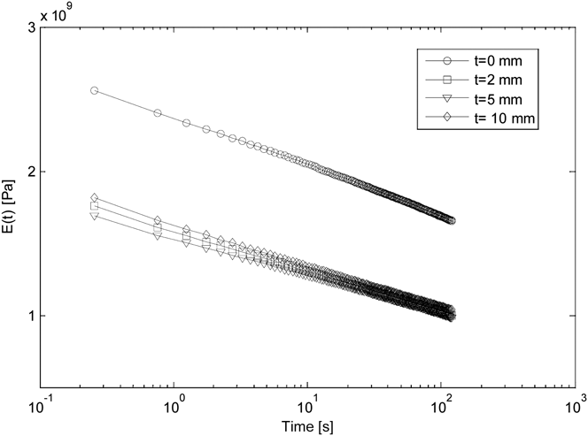
Same relaxation test as in the previous sections was conducted. In Fig. 8 the relaxation moduli for the four new specimens are presented.
Influence of the support material on the relaxation modulus for B90 specimens.
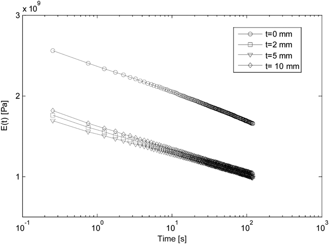
From the results, it can be inferred that the existence of support material causes notable differences in mechanical behavior. The 0 mm part (with no additional support material) presents similar values and behavior for the relaxation modulus as those that were previously calculated for the 90° sloped parts in the previous series. On the other hand, significantly lower values were obtained for those parts with artificially added support material. Another interesting fact is that this result seems to be independent from support thickness.
This result confirms the hypothesis of support material introducing a shielding effect upon UV over-curing of certain surfaces and thus, reducing material stiffness. Consequently, the lateral side of the part covered by support material would receive a lower UV exposure, and the overall properties of the part would be comparatively lower. Therefore, a softer material should be obtained in this lateral side. This situation is opposite to that of the no-supported part, where both sides would be continuously under UV exposure during manufacturing. To provide additional proofs of this hypothesis, Barcol hardness tests (Impressor) were carried out on the four specimens. Samples were obtained using 5 mm steps in the longitudinal direction for both sides of the specimens (with and without supported material). The averaged hardness (Barcol units) value for the no-supported side was 10, whereas a 2 hardness value was encountered for the side where support material was artificially added. As it was expected, the 0 mm thickness support specimen presents the same hardness on both lateral sides. This result provides a consistent explanation for the detected higher stiffness, and also points out to UV over-curing as the cause of this behavior. Finally, it is remarkable that the 90° sloped parts with artificially added support material present relaxation moduli close or even lower than the B60-B75 parts. This means that the expected orthotropic-like behavior would be obtained with B angle if the over-curing effect upon 90° nonsupported specimens is discounted.
IV. CONCLUSIONS
Experimental work has been conducted to evaluate mechanical properties dependence of PolyJet parts with respect to the time of force appliance and the orientation of the parts in the tray. Tests have been particularized using Stratasys RGD240 photopolymer as model material. The results indicate that mechanical properties of parts built in this material are time-dependent, so their behavior could be described using the relaxation modulus E(t). In a similar way, surface slope, characterized through the inclination angle of part surface with respect to the Y axis (B), has also great influence upon material properties. Whereas E(t) values are maximum for 0° sloped surfaces, they progressively decrease to a minimum at the 60°–75° orientation. Instead, vertical (90°) slopes present an abrupt increase in E(t) values. Additional experiments were carried out to determine the cause of this behavior, and results indicate that it should be related to a shielding effect upon UV curing caused by support material. Replacing data obtained for 90° specimens with data from alternative artificially supported specimens would provide short-of an orthotropic behavior.
As PolyJet software automatically adds support material as a function of part geometry and orientation, this shielding effect could be considered as inherent to the process. Even when the conclusions of this work could be incorporated to control software to obtain orthotropic-like characteristics, it seems more logical to incorporate them to a good-practises list. Thus, vertical surfaces with no support material affecting the UV curing should be expected to be more resistant to equivalent surfaces with shielding effect, and the designers should take notice of this circumstance.
Nevertheless, further investigations must be done to improve knowledge on how AM particular characteristics are affecting material mechanical properties.