1. INTRODUCTION
The universal vessel-borne Automatic Identification System (AIS) (Graveson, Reference Graveson2004) is a vessel-to-vessel and vessel-to-shore (and vessel-to-space) reporting system which broadcasts short fixed-length Time Division Multiple Access (TDMA) messages on the maritime dedicated Very High Frequency (VHF) band. It is defined by the International Telecommunication Union (ITU, 2001).
The AIS system is mainly used for the dynamic tracking of vessels as well as for navigation and collision avoidance (Silveira et al., Reference Silveira, Teixeira and Guedes Soares2013). The AIS communication system applies a Self-Organising Time Division Multiple Access (SOTDMA) technology and a communication protocol (ITU, 2001), automatically providing navigation information to vessels and shore stations, including position, identification, course and speed over ground as well as static and voyage-related information. On receiving the dynamic voyage information of vessels, the system can be helpful in collision avoidance, voyage scheduling and vessel management etc (Norris, Reference Norris2007; Silveira et al., Reference Silveira, Teixeira and Guedes Soares2013).
Satellites equipped with high sensitivity AIS receivers can make an important contribution to maritime surveillance. Nowadays, space-based AIS is a hot topic and widely studied (Cairns, Reference Cairns2005; Cervera et al., Reference Cervera, Ginesi and Eckstein2011; Carson-Jackson, Reference Carson-Jackson2012). The space-based AIS system can maintain long-range surveillance of vessels with wide coverage relative to the traditional AIS. When the satellite is flying across the ocean along the main routes, the AIS receiver on board receives AIS messages from the vessels within a coverage circle along the footprint of the satellite. Thus the space-based AIS system can be employed for space tracking, surveillance and for control logistics design of civilian vessels, and even military vessels (Cairns, Reference Cairns2005; Eriksen et al., Reference Eriksen, Høye, Narheim and Meland2006; Haakonsen Dahl, Reference Haakonsen Dahl2006; Cervera et al., Reference Cervera, Ginesi and Eckstein2011).
In order to speed up the practical application of space-based AIS, many countries and organisations have attached great importance to the research and development of such systems, focusing mainly on the study of the theory and key technologies of space-based AIS (Hicks et al., Reference Hicks, Clark and Stocker2005; Høye Reference Høye2006; Burzigotti et al., Reference Burzigotti, Ginesi and Colavolpe2012; Cheng et al., Reference Cheng, Chen and Chen2014; Reference Cheng, Chen and Chen2015). On the facets of theory and technology study, for example, interest is mainly on space-based AIS system modelling and optimisation, signal demodulation and aliasing signal blind source separation (Zhu et al., Reference Zhu, Liu, Jiang and Guo2012), multi-beam scanning helical antenna design (Cheng et al., Reference Cheng, Chen and Chen2015), AIS satellite network theory and method (Graziano et al., Reference Graziano, D'Errico and Razzano2012) and so on. With respect to AIS satellite development, America (Duffey et al., Reference Duffey, Huffine and Nicholson2008), Norway (Eriksen et al., Reference Eriksen, Høye, Narheim and Meland2006, Reference Eriksen, Skauen, Narheim and Helleren2010; Narheim et al., Reference Narheim, Helleren, Olsen, Olsen, Rosshaug, Beattie, Kekez and Zee2011), Canada (Brusch et al., Reference Brusch, Lehner, Schwarz and Fritz2010; Cain and Meger, Reference Cain and Meger2009), Germany (Holsten, Reference Holsten2009), Luxembourg (Burzigotti et al., Reference Burzigotti, Ginesi and Colavolpe2012), Europe (Tobehn et al., Reference Tobehn, Schonenberg, Rinaldo, Ginesi, Ginati and Sciberras2011) and China (Chen et al., Reference Chen, Chen, Zhao and Cheng2015), and some other countries and organisations, have launched their own AIS satellites. In China, two Nano satellites developed by the National University of Defense Technology (NUDT) of China, i.e., TianTuo-1 (Chen et al., Reference Chen, Chen, Zhao and Cheng2015) and TianTuo-3, mainly carrying space-based AIS receivers, are the canonical developments of space-based AIS systems and were respectively launched on 10 May 2012 and 20 September 2015.
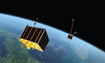
The TianTuo-3 Nano satellite constellation consists of one main satellite LvLiang-1 (weight 23 kg), one mobile phone satellite Smart (weight 1 kg) and four femto-satellites Stardust 1 ~ 4 (weight 0·1 kg). Among these micro-nano satellites, the mobile phone satellite was designed with the objective of verifying the feasibility of applying the motherboard of a mobile phone in space; the four femto-satellites were designed to examine the technology of construction of a self-organised network in space. After launching into sun-synchronous Low Earth Orbit (LEO) at a height of 496 km, the Smart mobile phone satellite was separated from the main satellite, then the four femto-satellites separated respectively from the main satellite and the mobile phone satellite. Figure 1 schematically illustrates the in-orbit diagram of the TianTuo-3 Nano satellite constellation, where the larger one is the main satellite LvLiang-1 and the smaller one is the mobile phone satellite Smart, both are accompanied by two femto-satellites. During the debugging stage of around three months, satellite space network authentication has been performed and all the main payloads work normally.
Illustration for the in-orbit flying of the TianTuo-3 constellation.

The main satellite of TianTuo-3, i.e., LvLiang-1 carries several payloads, including the newly designed space-based AIS receiver (hereafter called TT3-AIS), an Automatic Dependent Surveillance-Broadcast (ADS-B) system and an infrared camera. Among them, the AIS payload is a system newly designed in China whose weight is only around 320 g (receiver and antenna). Several kinds of new technology are applied in designing the TT3-AIS receiver based on the design of the TT1-AIS, including multi-channel technology, Doppler frequency shift estimation compensation technology, receiving antenna optimisation technology, and so on.
The orbit of TT3 is sun-synchronous with an inclination angle of 97·5° and the altitude is 524 km, so the orbit period is 94·5 minutes, thus TT3 covers all the surface of the Earth. Furthermore, due to the self-rotation of the Earth, the projection of the ground track of the satellite moves 15° westward every cycle and 1670 km equivalently in the equatorial plane. On the other hand, the swath width of TT3-AIS receiving antenna is 2250 km, so that the coverage area of the TT3-AIS receiver over the ground can be seamlessly joined. Having partly solved the signal conflict problems and having larger coverage over the ground, the AIS receiver on board TianTuo-3 has greatly improved the signal detection ability. During the debugging stage (20 September 2015 ~ 20 December 2015), the TT3-AIS worked smoothly in orbit, and effectively received AIS messages every day.
In this paper, we will not address the technology applied in designing the TT3-AIS system, but analyse the data received by TT3-AIS in the initial debugging stage (20 September 2015 ~ 20 December 2015) and try to analyse the ability of the TT3-AIS to help in rescuing, surveying, or tracking of special vessels, or analysing world shipping for economic studies.
The remainder of this paper is arranged as follows. The TT3-AIS data format is interpolated in Section 2. The receiving ability analysis of the TT3-AIS data is performed in the former part of Section 3, while the new type of data received by two new frequency channels is addressed in the latter part of Section 3. Conclusions and discussion are presented in the final section.
2. DATA FORMAT OF TT3-AIS
In design, the TT3-AIS receiver implements four frequency channels to receive the AIS messages synchronously. Two of them use frequency points at 161.975 MHz and 162.025 MHz, which are the official frequencies promulgated by the International Telecommunication Unit (ITU) for the traditional AIS system (ITU, 2001). The other two frequency channels at 156.775 MHz and 156.825 MHz, which are termed “space AIS channels”, are applied by the International Maritime Organization (IMO) from the ITU and particularly used for the long-ranged communication by the space-based AIS receiver and the maritime vessels (ref. to Rec. ITU-R M.1371-4, ITU, 2010).
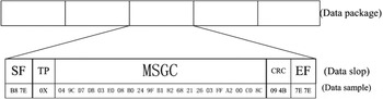
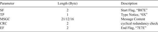
Figure 2 illustrates the composition and format of the data packages in the sequence received by the TT-3 AIS. An effective AIS message consists of Start Flag (SF), Type notice (TP), Message Content (MSGC), Cyclical Redundancy Check (CRC) code and the End Flag (EF) as shown in Figure 2. All the data are stored in hexadecimal format. The message starts with “B87E” as the starting marks and ends in “7E7E”. The length of the message is described in Table 1. Note that the length of the effective message content differs according to the type of the message; refer to Table 2.
TT-3 AIS data packet composition and format.

Content in an effective AIS message in TT-3 AIS.

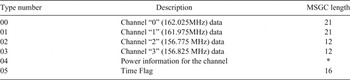
Description for the message type in the data package of the TT3-AIS.

The TP is an 8-bit number “0X” which distinguishes the data received by different frequency channels, the receiving power of the message, and the time flag. The meaning of the message types denoted by different numbers in TP is described in Table 2 in more detail. Note that the two numbers, i.e., “02” and “03”, are the denotation of the signals being received through the two space AIS channels. The last column is the length of the message content.
If the Type number is “00” or “01”, the message content in the “MSGC” field is the traditional AIS report, usually stored in 21 bytes which is indeed a 168-bit message known as the 168 AIS standard information. The navigation information, such as the message ID (MSG ID, which identifies the message type), user ID (UID, which should be the Maritime Mobile Service Identity (MMSI) number), navigational status, speed, course, latitude, longitude, coordinated UTC (UTCc), and communication status, can be decoded from this 168 AIS standard information according to the technical characteristics for an automatic identification system (Recommendation ITU-R M.1371-1) (ITU, 2001). There are 22 types of AIS report according to ITU-R M.1371-1, in which the message type 1, type 2 and type 3 are of the position report and are frequently sent and received.
For the two space AIS channels, the type number is “02” or “03”. The “MSGC” field is a 12-byte length piece of data which composes a message of 96 bits in total. This message is a long-range AIS broadcast message which is mainly dedicated to long-range communication and typically used by space-based AIS. The long-range AIS broadcast message, which must be solely transmitted on the space AIS channels, is termed “type-27 AIS message” in this paper since the MSG ID of this kind of message is always 27. Similar to the type 1, 2 and 3 messages for scheduled position reports, the transmission of the “type-27 AIS message” contains navigational information including position, speed over ground, course over ground, navigational status and so on (Recommendation ITU-R M.1371-5) (ITU, 2010). The total number of bits in the “type-27 AIS message” has been compressed to be 96 bits which allows for increased propagation delays associated with long-range detection (Recommendation ITU-R M.1371-4) (ITU, 2010).
According to one statistical analysis of all of the AIS data received by the TianTuo-1 nano-satellite (Li et al., Reference Li, Chen and Chen2017), though more than 90% of the AIS data package is constructed with the UTC direct synchronisation method, due to the limitation of the communication state of the SOTDMA, the ratio of directly sending time information in AIS data is as low as 10 ~ 20% even if the UTC direct synchronisation method is used. It is necessary to obtain the time information of the received AIS data message, especially for the continuous tracking of some special vessels.
One important improvement in the TianTuo-3 space-based AIS receiver is the time-flag inserted from the satellite management system into the received AIS data package with a rate of one time-flag per minute. In the message package, if the Type number is “05”, the message content in the “MSGC” field represents the time information injected by the satellite management system when the data is received. Thus, when decoding the other types of data, the time information of “minute” can be inserted with the time decoded from the latest “05” time message. For the time information of the “second” value, this can be obtained according to the state of SOTDMA message communication information in decoding this message. Thus the accurate time information can be added to each message from the TT-3 AIS data package.
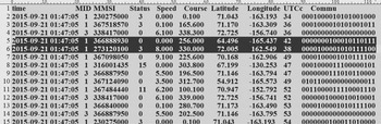
After decoding the data package, the navigation message can be obtained in time sequence and stored for advance analysis. Figure 3 presents an example to show the decoded message from data received by TT3-AIS on 21 September 2015. In this example, the main information for navigation is reported, including: (Column 1) the time in minutes when this message was received, (Column 2) the Message ID (MSG ID), (Column 3) the user ID (MMSI), (Column 4) the navigational status, (Column 5) the Speed over ground (SOG, unit is in knots), (Column 6) the Course over ground (COG, unit is in degrees), (Column 7) the Latitude (unit is in degrees), (Column 8) Longitude (unit is in degrees), (Column 9) the coordinate time in UTC seconds, and the code for communication status which is not used in our analysis. The fourth column is the navigational status. It is four bits long and is used for indicating the current navigational status of the vessel, for example, 0 = under way using engine, 1 = at anchor, 2 = not under command, and so on. Note that the exact time information can be obtained by the “time” column (Column 1) and the “UTCc” column (Column 9). In summary, the AIS message received by the TT3-AIS receiver can be arranged by accurate time information due to the time-flag inserted into the received AIS data package, which make it valuable in continuously tracking vessels.
Example of the navigation message after decoding from TT3-AIS data.

3. RECEIVING ABILITY ANALYSIS FOR THE TT3-AIS DATA
After its launch into the sun-synchronous orbit at a height of 496 km on 20 September 2015, the TianTuo-3 constellation was under debugging from 20 September 2015 to 20 December 2015. During its debugging stage, the attitude was stable, the temperature was normal and all the payloads worked normally. During the debugging stage, the TT3-AIS receiver did not work all the time due to the debugging tasks. For example, the AIS payload was shut down for two time spans, 24 September 2015 to 8 October 2015 and 25 November 2015 to 17 December 2015 for satellite debugging tasks.
3.1. Data overview and analysis
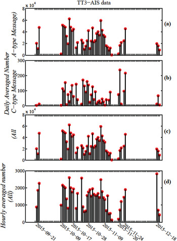
Figure 4 is the overview for the AIS messages received by the TT3-AIS during the debugging phase. As is seen, the TT3-AIS only received AIS data from maritime vessels for a total of 46 days. After decoding, a total of 1,271,629 effective messages were obtained. Panels (a-c) of Figure 4 respectively show the daily averaged A-type numbers, C-type numbers and the total numbers of the AIS message, where, “A-type” represents the message decoded from data received by the traditional frequency channels “00” and “01” (see Table 2); while “C-type” stands for those received from the new frequency channel “02” and “03” (refer to Table 2) which is of the type 27 AIS message (Recommendation ITU-R M.1371-4) (ITU, 2010), i.e., the long-range AIS broadcast message. As is seen in Figure 4(c), the maximal value of the daily averaged number during the debugging stage is less than 300, thus the type 27 message is only a small fraction of the total messages received by the TT3-AIS receiver.
Overview of the TT3-AIS data during the debug stage. (a ~ c) A-type, C-type and total numbers of the AIS message. (d) Hourly averaged number of AIS messages received by TT3-AIS.

Figure 4(d) shows the hourly averaged numbers of the AIS messages received by TT3-AIS during the debugging phase in orbit. The received message numbers can represent the detection ability of the TT3-AIS receiver. As shown in Figure 4(d), in the detection phase (46 days), the average message number was about 500 ~ 1000 per hour over 13 days; while for the other 33 days, the average message number was about 1500 ~ 2500 per hour. It is especially stable and averaged around 1700 per hour during a stable working stage between 9 October and 14 November 2015.
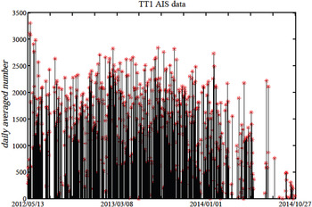
To make comparison with the receiving ability of the previously launched AIS nano-satellite TianTuo-1, the daily average number of the AIS messages received by TianTuo-1 was studied and the result is plotted in Figure 5. The time scope for analysis is from 13 May 2012 to 27 October 2014, almost covering the whole lifetime of TianTuo-1. Because of the lack of the time stamp in TianTuo-1, it is hard to determine the time of the AIS messages and thus impossible to estimate the hourly averaged received number of the AIS message in this satellite. However, the daily averaged number can be obtained according to the receiving record at the ground station. As is shown in Figure 5, most portions of the daily averaged number of messages received by the TT1-AIS receiver are about 1500 ~ 2000. The mean and max value of the daily averaged number is respectively 1406 and 3303. Comparing the results of Figure 4(c-d) and Figure 5, the detection ability of the TT3-AIS receiver has been improved greatly in contrast with the TT1-AIS receiver, and the average message number per hour of the former amounts to the average message number per day of the latter. However, in real flight, the receiving ability of TT1-AIS was higher than that in the ground station due to the limitation of the communication between TT1 and the ground station. Thus the receiving ability of TT3-AIS is approximately ten times the previous nano-satellite TianTuo-1 AIS.
The daily averaged number of AIS messages received by the TianTuo-1 AIS receiver.

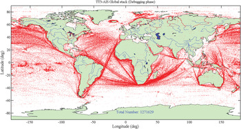
A total of 1,271,629 effective AIS messages were obtained by decoding from all the data received by the TT3-AIS receiver in the whole running time during its in-orbit debugging phase. Figure 6 shows the navigation information (position and speed) of all the AIS messages on a world map. It is clear that there are a large number of vessels distributed on the main sea-route channels, including the East Asia, Indian Ocean, West Asia, Mediterranean, Western Europe channel, and the East Asia, Indian Ocean, Cape of Good Hope, the Atlantic, Western Europe or North America channels. In addition, because of the high density of vessels which causes abundant message collisions, a number of detection messages are lost in some areas such as the Mediterranean, Gulf of Mexico and South China Sea.
The global distribution of the vessels in the world map derived from AIS messages received by TT3-AIS during the in-orbit debugging phase.

3.2. Analysis of receiving ability for tracking a single vessel
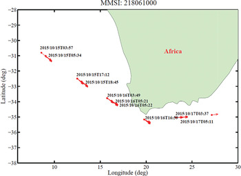
In this subsection, the tracking ability of TT3-AIS for a marine target is analysed by case study. Figure 7 shows the track of a vessel whose MMSI is 218061000 from 15 to 17 October 2015, which is obtained from TT3-AIS. This vessel passed the Cape of Good Hope from the Atlantic in the direction of the Indian Ocean during the period. The red points denote the location of this vessel and the arrows denote the course and speed. The time of receiving the AIS message is shown in text. As shown in Figure 7, every “point” in the figure represents many “points” in fact, which means there are several detection messages over a short time interval.
The track of a vessel whose MMSI is 218061000 by TT3-AIS.

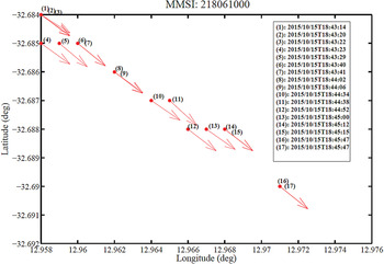
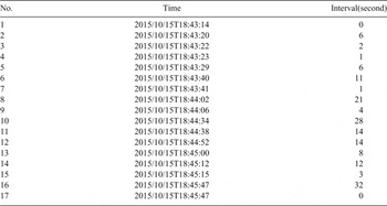
Figure 8 is a magnification of the 4th “point” in Figure 7 at approximately 18:45 UT on 15 October 2015. In this zoomed-in plot, each point represents one AIS message for the vessel whose MMSI is 218061000 and the receiving time for each point has been identified. It is obvious that the vessel mentioned above has been detected more than ten times by TT3-AIS over about three minutes at around 18:45 UT. Table 3 lists the corresponding detection moment and the time interval at all of the points is shown in Figure 8. As shown in Figure 8 and Table 3, TT3-AIS received the message from this vessel every few seconds and decoded the basic navigation information (location, status, course and speed) in real time. The largest time interval is 32 s, the smallest is 1 s and the average interval is 10·87 s.
The track of a vessel whose MMSI is 218061000 by TT3-AIS.

Time interval of the message for the vessel whose MMSI is 218061000 received by TT3-AIS as shown in Figure 8.

We have performed analysis on the detection ability of tracking a single vessel by TT3-AIS. The time interval is about 10 s, which makes it real-time tracking. The analysis result indicates that TT3-AIS can track and monitor one vessel continuously during the time of overhead passing of the satellite. However, the tracking will stop when the satellite passes out of the coverage area. Construction of an AIS constellation (Graziano et al., Reference Graziano, D'Errico and Razzano2012) in LEO to shorten the revisit time will be a good way to solve this problem.
Figure 8 shows that the vessel appears to be moving laterally in a straight line for bursts of readings before moving along its course vector. Such types of movements of the vessel may be abnormal behaviour, which may be caused by something blocking the signal, e.g. waves, other vessels, or even a rock and so on, within such a small region and within such a short time interval. However, the analysis of the tracking is beyond the scope of this study and remains for the future.
3.3. Analysis of type-27 AIS message from new frequency channels
As addressed in Section 2, the TianTuo-3 space-based AIS receiver (TT3-AIS) is designed to use four frequency channels to receive AIS messages. After its launch, TT3-AIS has received small portions of the AIS message from the new frequency channels. This is the long-range AIS broadcast message from Class A ship-borne mobile equipment.
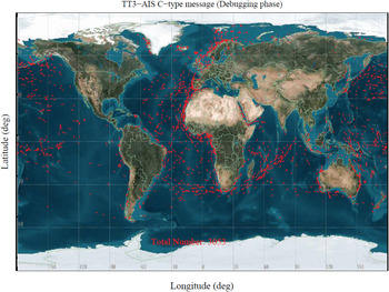
In Figure 4(b) we have shown the “C-type” messages from the frequency channels “02” and “03”. The total number of “C-type” messages is 3053 among the effective messages decoded from the data received by TT3-AIS in the debugging stage. Thus the ratio of “C-type” message is only 0·24%. These 3053 messages correspond to 1480 MMSI numbers, i.e., at least 1480 Class-A vessels have been equipped with an AIS with the new frequency channels. These vessels have been sailing around the world, as shown in Figure 9 which plots the navigation information (position and speed) decoded from the “C-type” message on a world map covering the debugging stage.
Global distribution of the navigation information (position and speed) obtained from TT3-AIS “C-type” message within the debugging stage.

4. CONCLUSION AND DISCUSSION
The AIS receiver on board the main satellite of the TianTuo-3 constellation, LvLiang-1, is a new generation of AIS receiver. Several types of new technologies have been applied in designing this AIS receiver based on the design of the TT1-AIS, including multi-channel technology, Doppler frequency shift estimation compensation technology, receiving antenna optimisation technology, and so on. Having partly solved the signal conflict problems and had larger coverage on the ground, the AIS receiver on board TianTuo-3 has greatly improved the signal detection ability.
In this paper, analysis of the data received by the AIS receiver during the TianTuo-3 debugging stage is performed in detail. The results include: (1) the AIS message received by the TT3-AIS receiver can be arranged by accurate time information due to the time-flag insertion into the received AIS data package, which makes it valuable in continuous tracking of vessels; (2) during the debugging stage, the TT3-AIS receiver worked for about 46 days and had received a total of 1,271,629 effective messages from maritime vessels. The hourly averaged count of the messages received by the TianTuo-3 AIS is between 1500 ~ 2500, which is about ten times the previous TianTuo-1 AIS; (3) with average updating data rate of only about 10 seconds, TianTuo-3 AIS is capable of real-time tracking to a single vessel during the time scope of overhead passing of the satellite; (4) having set two receiving frequency channels which are mainly dedicated to long distance communication and used by the space-based AIS, TianTuo-3 implements four-frequency detection at the same time. A small portion of Class-A vessels (at least 1480) have been equipped with the new AIS equipment sending long-range AIS broadcast messages with these two new frequency channels up to 20 December 2015.
In conclusion, the TianTuo-3 space-based AIS receiver is capable of continuous reception of AIS messages sent by global maritime vessels. The preliminary results based on the TT3-AIS data during the debugging stage are of significant importance for the practical application of the TT3-AIS data. The AIS aliasing signal conflict is an insurmountable problem for space-based AIS. The conflict degree is closely related to factors such as the orbit altitude, the coverage range, the maritime traffic, the width of antenna scanning beam, the number of vessels in the coverage range and so on (Cheng et al., Reference Cheng, Chen and Chen2014). TT3-AIS has been designed fully considering the signal demodulation and aliasing signal blind source separation and multi-beam scanning helical antenna designing (Cheng et al., Reference Cheng, Chen and Chen2015) and thus the signal detection ability is greatly improved compared to the previous TianTuo-1 satellite. However, the receiving ability of the TT3-AIS is still in a lower level compared to the most advanced space-based AIS in the world. For example, the Vesselsat-1 actually collects about 900,000 messages per day, and Vesselsat-2 up to 1,200,000 (Buursink et al., Reference Buursink, Ruy, Schwarzenbarth, Van Schie, Frappé, Ries and Moser2012). The most probable reason is that the base noise of the satellite in the AIS receiving frequency is too high in some situations and thus interrupts the received AIS signal. This shortcoming will be overcome in the next AIS receiver and the receiving ability will be improved.
ACKNOWLEDGEMENTS
This research has been supported by the National Natural Science Foundation of China under Grant 41004132 and 61302092, and the National University Defense Technology Project under Grant ZDYYJCYJ20140701.