Introduction
Microstrip patch antennas (MPAs) are quite common in modern wireless communication systems due to their low profile, ease of manufacture, and compatibility with both planar and conformal designs [Reference Mishra, Singh, Satheesha, Verma and Singh1]. Typically, an MPA consists of a thin metal patch positioned over a ground plane with a dielectric substrate. This configuration allows for designs that are both compact and lightweight [Reference El-Hakim and Mohamed2].
Research has examined various patch shapes, such as circular, triangular, and elliptical patches; however, square and rectangular patch geometries are predominantly preferred due to their ease of construction, simplicity of analysis, and consistent radiation characteristics [Reference Mishra, Singh and Singh3]. By selecting appropriate patch designs, feeding mechanisms, and substrate materials, one may tailor the operating frequency, bandwidth, and radiation patterns of MPAs [Reference Fan, Jiang, Liu, Xiu, Lin and Xu4]. Conventional MPAs include inherent constraints, such as restricted bandwidth and diminished gain. These limitations have prompted investigations into methodologies such as slot loading, parasitic elements, and array configurations to enhance their efficacy [Reference Hu, Li, Zhang, Liu, Wu and Wang5, Reference Chen, Yang and Nie6]. Consequently, MPAs have become a feasible option for incorporation into 5G, satellite, and Internet of Things (IoT) computing systems. An array patch antenna arrangement consists of many microstrip patch elements arranged systematically to enhance performance regarding gain, bandwidth, and radiation characteristics [Reference Nadar, Jeyaprakasam, Tharcis, Vivekanand, Eswaralingam, Louis, Arul, Ahmed, Chellappa, Muthukutty and Gopalakrishnan7]. A 1 × 2 patch array antenna typically consists of two identical patch elements, which may be either rectangular or square, arranged linearly along a single axis. This antenna is often provided by a corporate or serial feed network [Reference J, Mishra and Satheesha8]. This arrangement significantly enlarges the total aperture size, enhancing directivity and peak gain relative to a patch composed of a single element. This construction also guarantees controlled beam shaping for applications requiring directed EM waves [Reference Rahman, Islam, Yong, Islam, Alam, Hakim, Al and Moniruzzaman9]. One of the critical parameters is the element spacing, often chosen to be about half a wavelength (λ/2) at the designated frequency. This is executed to reduce grating lobes and guarantee that constructive interference is maintained in the appropriate direction [Reference Serup, Pedersen and Zhang10].
Modern wireless communication systems depend critically on multiple-input multiple-output (MIMO) antennas, which allow simultaneous transmission and reception of many data streams via separate antenna components. Without increased bandwidth or transmit power, MIMO antennas greatly improve system capacity, dependability, and spectral efficiency by using spatial diversity and multiplexing. MIMO is an essential technology for high-speed applications like 5G and beyond, as its basic idea is to use the multipath propagation environment to achieve enhanced link quality and greater throughput. MIMO antennas present design difficulties, including maintaining high isolation between ports (usually >20 dB), minimizing envelope correlation coefficient (ECC < 0.005), and optimizing parameters like gain, efficiency, and impedance bandwidth to guarantee strong performance in complex propagation environments.
The deployment of 5G networks has coincided with a dramatic increase in funding and enthusiasm for research into and investment in next-generation wireless communication systems from both the academic and corporate sectors. In order to support applications that need very high data rates, 5G networks use millimeter-wave (mmWave) communications, which provide a lot of capacity. At mmWave frequencies, antenna electrical performance poses specific design challenges, such as the need for a wide operating bandwidth, a constant gain, and an asymmetric radiation pattern. Wideband or multiband antennas are often used to manage the different frequency bands. The form factor, cost structure, and manufacturability of the wideband mmWave antenna must be carefully considered throughout its design. At these frequencies, path loss and signal attenuation are rather severe; therefore, to fulfil the link budget requirements, high-gain MIMO antennas with stable radiation characteristics were used.
Recent advancements in 4-port MIMO antenna designs for 5G mmWave applications, particularly in the 28 GHz frequency band, have focused on achieving compactness, broad bandwidth, high gain, and reduced mutual coupling to meet the stringent requirements of next-generation wireless systems. Tadesse et al. [Reference Tadesse, Acharya and Sahu11] introduced a planar 4-port MIMO antenna utilizing split-ring resonator metamaterials to attain dual-band functionality at 28 and 38 GHz, featuring bandwidths of 26.6–29 GHz and 37.3–39.3 GHz, port isolation exceeding 25 dB, and an ECC below 0.005. Khabba et al. [Reference Khabba, Amadid, Ibnyaich and Zeroual12] developed a compact dual-wideband 4-port MIMO antenna including a cross-shaped decoupling structure, attaining an isolation of over 30 dB, an ECC of 0.0005, and a radiation efficiency of 98%, making it suitable for small 5G terminals. The authors in [Reference Sehrai, Asif, Shoaib, Ibrar, Jan, Alibakhshikenari, Lalbakhsh and Limiti13] present a MIMO antenna system for mmWave 5G wireless communication services, consisting of four HP-shaped antennas. The antenna operates at a wideband of 36.83–40.0 GHz, attaining a peak gain of 6.5 dB and a maximum element-isolation of −45 dB. Its radiation efficiency is above 80%, making it a potential contender for upcoming communication applications. The authors in [Reference Kamal, Yang, Ren, Altaf, Kiani, Anjum, Iqbal, Asif and Saeed14] present a novel single-layer MIMO antenna for 5G 28 GHz frequency band applications. The antenna operates in the Ka-band, ideal for 5G mmWave communication. The design consists of triplet circular rings and an infinity-shaped shell. The antenna achieves a simulated gain of 6.1 dBi and a measured gain of 5.5 dBi. The authors in [Reference Sharma, Sharma, Sharma, Wadhwa and Kumar15] and [Reference Goyal and Modani16] present a compact design for a four-element MIMO antenna for mmWave communications, covering bands n257/n258/n261. The antenna uses a single circular patch with an inset feed, a half-disk parasitic patch, and two vertical stubs. The antenna is optimized using a Rogers RT/Duroid 5880 substrate. The antenna has an ECC of less than 0.002 and a diversity gain (DG) of over 9.99 dB, with isolation between neighboring elements of less than −23.5 dB. Goyal and Modani [Reference Goyal and Modani16] concentrated on miniaturization and enhanced isolation in a 4-port MIMO antenna at 28 GHz, with minimal isolation loss and ECC, making it suitable for 5G devices. Sufian et al. [Reference Sufian, Hussain, Abbas, Awan, Choi and Kim17] presented a series-fed planar array 4-port MIMO antenna for 28 GHz IoT applications, with a peak gain of 10.6 dBi, minimal mutual coupling below −40 dB, and an ECC of less than 0.0001. Tiwari et al. [Reference Tiwari, Sharma, Singh and Kumar18] designed a versatile dual-band 4 × 4 MIMO antenna for 28/38 GHz wearable applications, with gains of 4.15 and 7.73 dBi, overall efficiencies of 80.13% and 85.44%, and a channel capacity of 21.61 bps/Hz. Aghoutane et al. [Reference Elalaouy, El Ghzaoui and Foshi19] introduced a dual-band, high-gain, 4-port mmWave MIMO antenna array designed for 28/37 GHz applications, emphasizing high gain and strong isolation. Singh et al. [Reference Singh, Dwivedi, Choubey and Singh20] proposed a compact dual-port mmWave MIMO antenna for the 30 GHz n257 5G band, using a modified C-shaped radiator and a mirrored element arrangement on Rogers RT/Duroid substrate to realize a small-size antenna with measured bandwidth around 28.82–31.30 GHz. Dwivedi et al. [Reference Dwivedi, Singh, Alzahrani, Chaitanya, Singh, Singh, Parashar and Tolani21] present a dual-port, dual-band mmWave MIMO antenna optimized with a Taguchi neural-network approach, using a slot-etched rectangular ring radiator and stepped-impedance microstrip feed to target 28 GHz and 34 GHz operation for 5G/next-generation mobile communication.
In this research work, a compact 4-port MIMO array antenna is designed and investigated for 28 GHz applications. The notable attributes of the proposed work are high gain and high isolation between the antenna elements. The stepwise evolution stages from a single antenna element to a 1 × 2 array antenna, then a further 4-port MIMO array antenna has been discussed with simulated and measured findings. The subsequent sections have been divided as follows: (a) Design and evolution stages for single antenna unit, (b) conversion of single antenna into 1 × 2 array antenna elements, (c) 2-port and 4-port MIMO array antenna design, (d) results and discussion, and (e) novelty justification.
Antenna configuration and design
In this part, we have undertaken a study of the suggested antenna design. Each step of this design serves a specific function to boost performance. The compact size of the single-element antenna may lead to bandwidth, gain, and efficiency limitations. We have created an array that demonstrates improved bandwidth, gain, and efficiency. MIMO is the definitive method to augment the aggregate data rate, promote system dependability, and increase communication quality.
Single antenna and evolution stages
This section examines and discusses the many stages of development for the proposed single antenna component. Three distinct steps (steps 1–3) are delineated to achieve the final configuration of the proposed antenna. A comparison study has been conducted based on the |S 11| (dB) values during this technique. Figure 1(a) illustrates that the same antenna undergoes three independent design modifications at each stage. The initial stage, step 1, begins with a basic rectangular patch antenna, which offers fundamental radiation characteristics but suffers from narrow bandwidth below 25 GHz. In the subsequent stage, the antenna geometry is modified in step 2 by introducing a rectangular notch into the patch, which improves impedance matching and initiates resonance behavior, thereby enhancing bandwidth, but not at 28 GHz. The following stage (step 3) incorporates an additional rectangular notch around the main radiator. These features create additional current paths, contributing to bandwidth enhancement and better impedance tuning at 28 GHz. The design in step 3 exhibits −30 dB of reflection coefficient values throughout the bandwidth of 26.92–29.20 GHz, as seen in Fig. 1(b), resonating at 28 GHz. After many rounds of parametric analysis, the definitive design (step 3) for a single antenna element has been established.
(a) Single antenna element evolution stages and (b) return loss of different stages.

Figure 1 Long description
The image A shows three stages of antenna design evolution. Step 1 features a basic rectangular radiating patch on an RT Duroid substrate. Step 2 introduces a rectangular notch 1 into the patch, enhancing impedance matching. Step 3 adds a second rectangular notch, further improving bandwidth and tuning. The image B shows a graph of return loss (vertical axis, dB) versus frequency (horizontal axis, GHz). Three curves represent the return loss for each design stage: Step 1, Step 2 and Step 3. Step 3 shows the best performance with a reflection coefficient of minus 30 dB between 26.92 GHz and 29.20 GHz, resonating at 28 GHz.
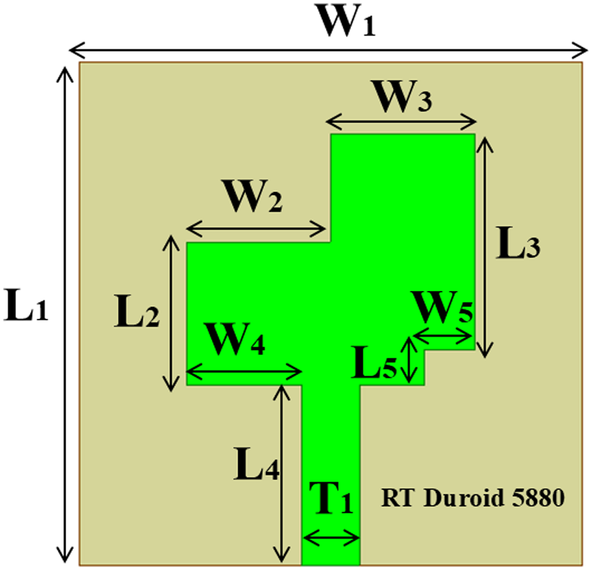
The final single antenna design is shown in Fig. 2 with the dimensional specification. The proposed antenna is made of copper printed on RT duroid substrate of relative permittivity of 2.2 and loss tangent of 0.0009, with a thickness of 0.8 mm. The suggested MIMO antenna model’s dimensions are shown in Table 1.
The geometrical layout of the single antenna element.

Figure 2 Long description
The dimensions are marked as L1, W1, L2, W2, L3, W3, L4, W4, L5, W5 and T1, indicating different lengths and widths of the antenna structure. The substrate is labeled 'RT Duroid 5880'.
Proposed specifications for a single antenna, together with their dimensions

Table 1 Long description
The table presents proposed specifications for a single antenna, detailing dimensions in millimeters for various parameters. Parameters L1 and W1 both have the largest dimension of 7 mm, indicating a potential symmetry in design. L5 has the smallest dimension at 0.5 mm, while W5 and T1 share dimensions of 0.7 mm and 0.8 mm respectively, suggesting a compact design for these components. The dimensions for L2, L3, and L4 range from 2 mm to 3 mm, and similarly, W2 to W4 range from 1.6 mm to 2 mm, indicating a consistent pattern in size allocation. These measurements are crucial for understanding the physical layout and potential performance characteristics of the antenna.
Design of 1 × 2 array antenna
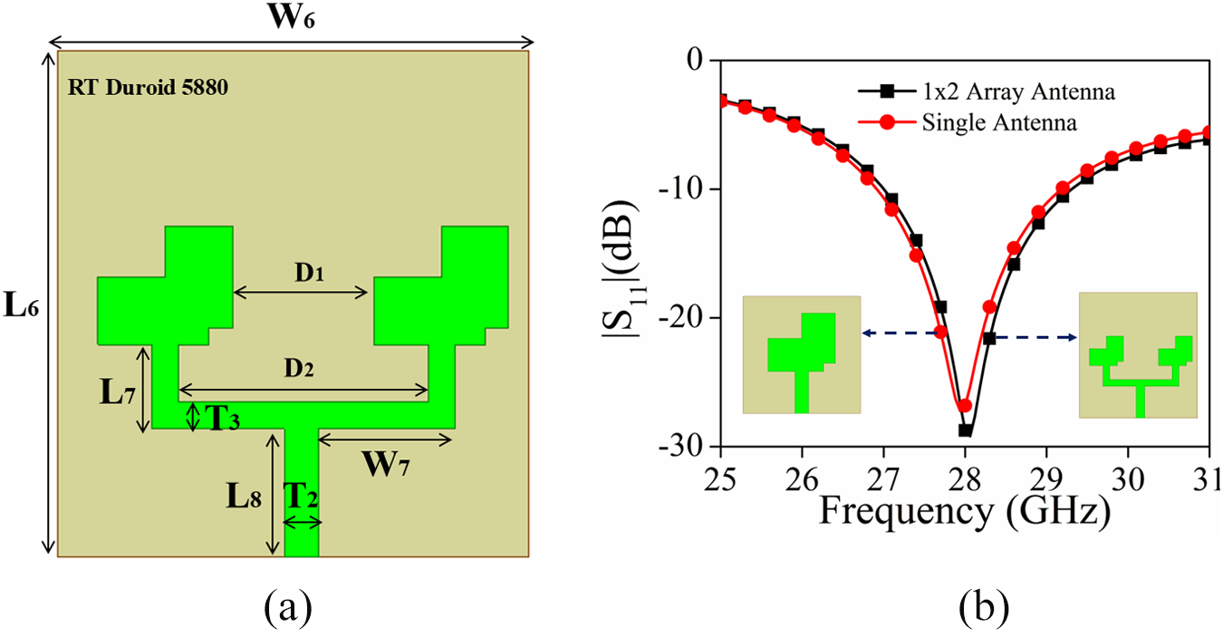
The single antenna unit presented in Fig. 2 has been converted into a 1 × 2 array configuration presented in Fig. 3(a) and associated return loss plot in Fig. 3(b). Fig. 3(a) shows a 1 × 2 array antenna configuration designed for 28 GHz operation, likely using a microstrip-based topology on a high-frequency substrate such as Rogers RT/Duroid 5880. This array consists of two identical antenna elements placed linearly along a single axis, enabling increased directivity and gain compared to a single-element design. Each element in the array retains the features of the single antenna to maintain impedance matching and bandwidth at the mmWave band. The spacing between elements is typically around half a wavelength (λ/2 at 28 GHz ≈ 5.36 mm) to ensure constructive interference in the broadside direction and to prevent grating lobes. A microstrip feed network, possibly using T-junction power dividers, is employed to distribute power equally with proper phase alignment to both elements. The result is enhanced gain (typically >12 dBi), which makes the 1 × 2 array a practical choice for compact 5G mmWave antenna systems needing higher directivity without significantly increasing the antenna footprint. The return loss graphs of a single antenna element and a 1 × 2 array antenna are depicted in Fig. 3(b), confirming that the impedance matching behavior for both single antenna and array antenna is the same. The dimension of the proposed 1 × 2 array unit antenna is presented in Table 2.
The proposed 1 × 2 array antenna configuration: (a) geometrical layout and (b) return loss.

Figure 3 Long description
The image consists of two sub-images. It includes dimensions labeled as L6, W6, L7, W7, D1, D2 and T3, with the substrate labeled as RT Duroid 5880. The layout features two identical antenna elements placed linearly. The second sub-image (b) is a graph depicting the return loss in decibels (dB) against frequency in gigahertz (GHz). The graph compares the performance of a 1x2 array antenna and a single antenna. The x-axis is labeled 'Frequency (GHz)' ranging from 25 to 31 and the y-axis is labeled '|S11|(dB)' ranging from -10 to -30. The 1x2 array antenna is represented by a black line and the single antenna by a red line, both showing a dip around 28 GHz, indicating impedance matching at this frequency. Insets show the antenna designs for reference.
Proposed specifications for a 1 × 2 array, 2-port MIMO, and 4-port MIMO antenna, together with their dimensions

Table 2 Long description
The table provides dimensions in millimeters for various parameters related to antenna specifications. Parameters L6 to L10 range from 0.5 mm to 7 mm, while W6 to W10 range from 0.7 mm to 7 mm. Notably, T2 and T3 have dimensions of 1 mm and 0.8 mm, respectively, indicating a slight variation in thickness. D1 and D2 are significantly larger, measuring 4.2 mm and 7.4 mm, suggesting these may be related to larger components or overall antenna size. The data allows for comparison between different parameters and their corresponding dimensions, highlighting the compact nature of the antenna design.
Figure 4 illustrates the distribution of E-field strength for a 1 × 2 array antenna designed for operation at 28 GHz. At the resonant frequency, significant field strengths are observed along the feed lines and patch edges, particularly near the slots or stubs, emphasizing areas of increased electromagnetic activity and effective radiation. The distribution shows that the current is primarily confined within each radiating element, exhibiting minimal coupling among them – indicating effective isolation, which is critical for array performance in mmWave applications. The symmetry noted in current patterns affirms appropriate excitation, enabling constructive interference in the desired direction. This constructive field behavior highlights the antenna’s suitability for high-gain, low-interference operation in compact 5G mmWave systems, verifying the effectiveness of the array design and element placement.
Field distribution of the proposed 1 × 2 array antenna.

Figure 4 Long description
A dashed line connects these areas, labeled 'Approx lambda over 2', indicating the distance between them. The background features a gradient pattern, suggesting varying energy levels.
MIMO antennas
To address the current requirements of 5G mmWave applications, 2-port and 4-port MIMO antennas have been designed using the 1 × 2 array antenna as the unit element. The geometric layout of the 2-port and 4-port MIMO array antennas, along with dimensional captions, is presented in Fig. 5(a) and (b), respectively. The detailed design process for these antenna modules at various phases is illustrated in Fig. 5(c). The accompanying figures collectively showcase a clear and structured progression in MIMO antenna design, starting with fundamental element-level innovation and culminating in a robust multi-port MIMO array. The “Stepwise Growth” diagram captures the conceptual evolution from a single-element design to a more complex configuration. This gradual transformation involves iterative modifications in geometry, radiating element orientation, and feed network arrangement. This stepwise refinement ensures that the antenna evolves not only in form but also in function, maintaining performance integrity at each phase. The fabricated 4-port MIMO array antenna front and back module is shown in Fig. 5(d).
MIMO array antennas: (a) 2-port, (b) 4-port, (c) overall design growth, and (d) fabricated antenna.

Figure 5 Long description
The image C illustrates the design growth from a single antenna to a 1 by 2 array 2-Port MIMO antenna and then to a 1 by 2 array 4-Port MIMO antenna, with arrows indicating progression. The image D shows the fabricated 4-Port MIMO array antenna with front and back views, labeled with Port-1, Port-2, Port-3 and Port-4.
The 2-port MIMO array marks the initial realization of spatial diversity by introducing dual radiating elements placed orthogonally to minimize mutual coupling. The scattering characteristics (|S 11|, |S 12|, |S 21|, and |S 22|) of the 2-port MIMO array antenna are shown in Fig. 6(a). Upon reviewing Fig. 6(a), it is evident that the isolation between the antenna elements exceeds 23 dB. The 4-port array then represents the final stage of scalability, applying the same design principles to enable higher-order MIMO configurations. The scattering parameters of this 4-port MIMO antenna array are illustrated in Fig. 6(b). The spatial diversity of the proposed configuration results in isolation greater than 28 dB across the entire operating bandwidth of 26.92–29.20 GHz between each antenna element. Overall, the figures present a methodical, simulation-validated progression – from single-element enhancement to fully scalable multi-port integration – driven by the real-world application needs of 5G and high-capacity wireless networks.
Scattering parameters of (a) 2-port MIMO array antenna and (b) 4-port MIMO array antenna.
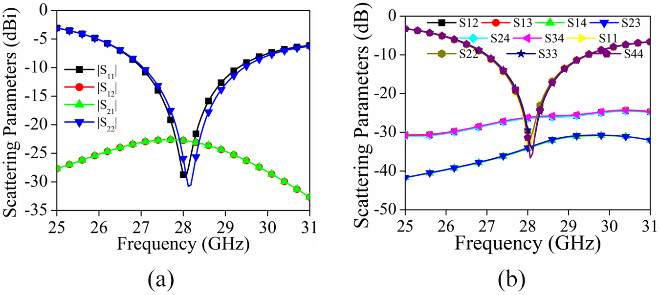
Figure 6 Long description
The x-axis is labeled Frequency in gigahertz, ranging from 25 to 31. The y-axis is labeled Scattering Parameters in decibels. Four curves are plotted: S subscript 11, S subscript 12, S subscript 21 and S subscript 22. The S subscript 11 and S subscript 22 curves show a dip around 28 gigahertz, while S subscript 12 and S subscript 21 remain relatively flat. The image B shows a graph of scattering parameters for a 4-port MIMO array antenna. The x-axis is labeled Frequency in gigahertz, ranging from 25 to 31. The y-axis is labeled Scattering Parameters in decibels. Eight curves are plotted: S subscript 12, S subscript 13, S subscript 14, S subscript 21, S subscript 23, S subscript 24, S subscript 31 and S subscript 41. The curves show varying levels of scattering across the frequency range, with some curves intersecting around 28 gigahertz.
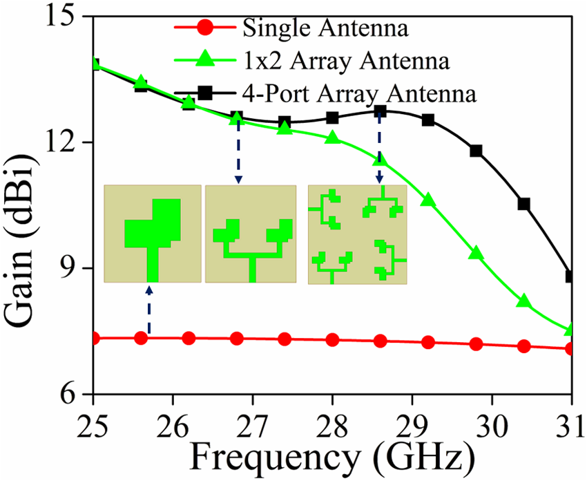
The gain distribution for the single antenna, 1 × 2 array antenna, and 4-port MIMO array antenna is shown in Fig. 7. The increase in gain from a single antenna (7.3 dBi) to a 1 × 2 array (12.78 dBi), and then to a 4-port MIMO array (13.50 dBi), is attributable to array theory and spatial diversity principles. An individual antenna has intrinsic limitations in aperture and directivity, resulting in a modest gain of 7.3 dBi, appropriate for omnidirectional or semi-directional applications. Replicating and configuring this singular element as a 1 × 2 linear array enhances the effective aperture, enabling the antenna to concentrate energy in a specified direction, hence substantially increasing directivity and total gain to 12.78 dBi. This enhancement is ascribed to constructive interference of emitted waves and optimum element spacing (often λ/2), which guarantees minimum mutual coupling and maximal beam reinforcement in the intended direction. Extending this setup to a 4-port MIMO array incorporates more radiating components and spatial diversity, therefore mitigating fading effects and enhancing the effective radiation aperture. The gain enhancement from the 1 × 2 array to the 4-port MIMO array (13.50 dBi) is very minor; yet, this advancement signifies beam shaping, element interaction, and potentially optimized array shape that together improve directional radiation without substantially enlarging the footprint. Additionally, the MIMO structure enables concurrent multi-beam operation or beam switching, which is vital for high-capacity 5G mmWave applications, where elevated gain, enhanced coverage, and spatial multiplexing are critical.
Gain (dBi) of the proposed antenna modules.

Figure 7 Long description
The graph shows gain in dBi on the y-axis and frequency in GHz on the x-axis, ranging from 25 to 31 GHz. Three curves represent different antenna configurations: single antenna (red circles), 1x2 array antenna (green triangles) and 4-port array antenna (black squares). The 1x2 array antenna starts at around 12.78 dBi at 25 GHz and decreases gradually to about 9 dBi at 31 GHz. The 4-port array antenna begins at approximately 13.5 dBi at 25 GHz and decreases to about 10 dBi at 31 GHz. Insets show designs of the antennas corresponding to specific frequencies, illustrating their configurations.
Figure 8 illustrates the electric field distribution of the 4-port MIMO antenna. These plots are generated by energizing one port while maintaining the other port matched and terminated with 50 Ω. Analysis of Fig. 8 reveals that when port-1 is activated, the majority of the electric field is concentrated on the port-1 antenna structure, with a little influence seen on port-2 and port-4, which are situated in close proximity to port-1 (side-by-side orientation). In contrast, port-3 has a lower correlation with port-1. Identical behavior may be seen when additional ports are subsequently energized.
The E-field distribution of the proposed 4-port MIMO array antenna. (a) Port-1 excited. (b) Port-2 excited. (c) Port-3 excited. (d) Port-4 excited.

Figure 8 Long description
The field is concentrated around the Port-1 antenna structure, with some influence on nearby ports. The image B shows the E-field distribution with Port-2 excited, displaying similar concentration around Port-2. The image C shows the E-field distribution with Port-3 excited, with the field concentrated around Port-3. The image D shows the E-field distribution with Port-4 excited, with the field concentrated around Port-4. Each image includes a scale indicating the field strength in volts per meter, ranging from 0 to 2000 volts per meter.
Results and discussion
Reflection and transmission coefficients
When designing MPAs, a crucial metric to consider is the reflection coefficient. This coefficient measures the antenna’s matching accuracy concerning the feeding network or transmission lines. For antennas to perform optimally, they must maximize power transfer while minimizing signal reflections back to the source. Figure 9(a) represents the scattering parameters for the proposed 4-port MIMO array antenna, and Figure 9(b) represents the fabricated prototype with measurement setup. The simulated and measured scattering parameters of the proposed 4-port MIMO array antenna show strong agreement in return loss and isolation characteristics across the 28 GHz mmWave band. The simulated return loss (S₁₁) demonstrates a wide impedance bandwidth from 26.92 to 29.20 GHz (∼2.2 GHz) with a deep notch of −36 dB at 28 GHz, while the measured results indicate a slightly shifted bandwidth of 27.34–29.74 GHz (∼2.4 GHz) with a peak return loss of −43 dB at 28.43 GHz, suggesting efficient impedance matching in both scenarios. Figure 9 displays the prototype under test and the results of our MIMO antenna. Isolation, which measures the effect of one antenna’s radiation on adjacent antennas, is another vital metric engineers take into account when designing an antenna. Total performance improves due to reduced interference among the antennas, as evidenced by increased isolation. The simulated isolation between ports remains below 27 dB, while measured isolation maintains levels exceeding 30 dB, reflecting minimal mutual coupling and ensuring effective MIMO performance. The small deviations between simulation and measurement are attributed to fabrication tolerances and connector mismatches; however, the antenna overall demonstrates robust bandwidth, good isolation, and high suitability for 5G MIMO applications.
(a) Simulated and measured scattering parameters of the proposed 4-port MIMO array antenna. (b) Measurement of the fabricated antenna.

Figure 9 Long description
Image A shows a graph with scattering parameters (dB) on the y-axis and frequency (GHz) on the x-axis, ranging from 26 to 31 GHz. Multiple curves are plotted, including S subscript 11 Sim, S subscript 11 Mes, S subscript 12 Sim, S subscript 12 Mes, S subscript 13 Sim, S subscript 13 Mes, S subscript 14 Sim, S subscript 14 Mes, S subscript 21 Sim, S subscript 21 Mes, S subscript 22 Sim, S subscript 22 Mes, S subscript 23 Sim, S subscript 23 Mes, S subscript 24 Sim and S subscript 24 Mes. The curves show variations in scattering parameters across the frequency range. Image B displays the measurement setup for the antenna, including an anechoic chamber labeled 'Antenna Under Test' with ports 1 to 4 marked. A vector network analyzer is shown on the right, with matched terminated ports indicated. The setup is used for testing the antenna's performance.
Gain and efficiency
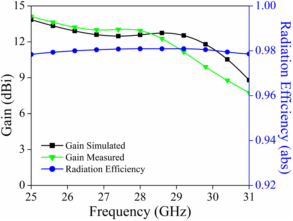
Figure 10 illustrates the simulated and measured gain as well as the simulated radiation efficiency plot for the presented antenna module. The figure compares the proposed antenna design’s simulated and observed gain performance across the operational frequency range, along with its radiation efficiency. The measured gain closely aligns with the predicted gain profile around 28 GHz, precisely in the middle of the intended mmWave 5G spectrum. The highest simulated gain is approximately 13.50 dBi, while the observed gain is about 13.20 dBi. This indicates that the difference is minimal, possibly due to tolerances in the manufacturing process and imperfections in the measurement equipment. Furthermore, the radiation efficiency curve remains high throughout the band, hovering around 98%. This signifies that the antenna effectively radiates power and experiences minimal loss. The close proximity of the simulated and measured findings demonstrates the robustness of the antenna design and the accuracy of the simulation model. Given its high gain and efficiency, the design is well-suited for high-data-rate wireless communication systems operating in the 5G mmWave range.
Simulated and measured gain and simulated radiation efficiency of the proposed 4-port MIMO array antenna.

Figure 10 Long description
The black line represents simulated gain, starting around 13.5 decibels at 25 gigahertz and slightly decreasing. The green line shows measured gain, starting near 13.2 decibels and decreasing more steeply. The blue line indicates radiation efficiency, starting near 0.98 and gradually decreasing. The graph includes labels for each line: 'Gain Simulated', 'Gain Measured' and 'Radiation Efficiency'.
Radiation pattern of the proposed MIMO antenna
Figure 11 thoroughly depicts the co- and cross-polarization characteristics of the proposed 4-port MIMO antenna array at 28 GHz in the XoZ and YoZ planes for each port (port-1 to port-4). In each subfigure, the co-polarization (denoting the desired polarization component) has a greater radiation magnitude than the cross-polarization (undesired orthogonal component), clearly indicating polarization clarity and isolation performance. The radiation patterns for the XoZ and YoZ cuts exhibit stable directed lobes with symmetric main lobes and diminished back lobes, indicating effective radiation and appropriate array setup. For all four ports, the cross-polarization levels are consistently at least 15 dB lower than their respective co-polarized peaks, indicating a low polarization mismatch and negligible interference between orthogonal components. The regularity of these patterns across all ports confirms the homogeneity of the design, which is essential for attaining dependable MIMO performance with less mutual coupling. This confirms the antenna’s appropriateness for 5G mmWave applications, where polarization control and pattern stability are critical.
Co- and cross-polarization of the proposed 4-port MIMO antenna at 28 GHz. (a) Port-1 XoZ plane. (b) Port-1 YoZ. (c) Port-2 XoZ. (d) Port-2 YoZ. (e) Port-3 XoZ. (f) Port-3 YoZ. (g) Port-4 XoZ. (h) Port-4 YoZ.

Figure 11 Long description
The image contains eight polar plots labeled (a) to (h), each depicting the co- and cross-polarization characteristics of a 4-port MIMO antenna at 28 GHz. Plots (a) and (b) show Port-1 in the XoZ and YoZ planes, respectively. Plots (c) and (d) display Port-2 in the XoZ and YoZ planes. Plots (e) and (f) illustrate Port-3 in the XoZ and YoZ planes. Plots (g) and (h) represent Port-4 in the XoZ and YoZ planes. Each plot includes lines for co-polarization and cross-polarization, with co-polarization having a greater magnitude. The radiation patterns exhibit stable directed lobes with symmetric main lobes and reduced back lobes, indicating effective radiation and array setup. Cross-polarization levels are consistently lower than co-polarized peaks, showing low polarization mismatch and minimal interference between orthogonal components.
Evaluation of the diversity performance of the proposed MIMO antenna
In order to determine whether or not the MIMO antenna system is effective, it is necessary to examine a number of features, which are referred to as “MIMO performance metrics.” The computation of these metrics may be obtained from the S-parameters, which provide substantial insights into the effect of mutual coupling and antenna impedance matching on the diversity performance of the MIMO antenna. These metrics can be used to determine the diversity performance of the antenna.
Envelope correlation coefficient
In a 4-port MIMO antenna system, the ECC is a vital metric that measures the correlation among radiating components, significantly influencing the system’s spatial diversity and multiplexing efficacy. To achieve the best MIMO performance, the ECC between each antenna pair – designated as ECCij, where i, j = 1, 2, 3, 4 and i ≠ j – should preferably be around 0.1, signifying little mutual coupling and substantial DG. In practical applications, ECC is often assessed using S-parameters based on high radiation efficiency assumptions, using the following relation [Reference Mishra and BV22]:
 \begin{equation}EC{C_{ij}} = \,\frac{{{{\left| {{S_{ii*}}{S_{ij}} + \,{S_{ji*}}{S_{jj}}} \right|}^2}}}{{\left( {1 - {{\left| {{S_{ii}}} \right|}^2} - {{\left| {{S_{ij}}} \right|}^2}} \right)\left( {1 - {{\left| {{S_{ji}}} \right|}^2} - {{\left| {{S_{jj}}} \right|}^2}} \right)}}\end{equation}
An accurate estimate of ECC in electrically compact, closely spaced multi-port antennas is given by this expression. To guarantee decorrelated radiation patterns and maximize the capacity of MIMO channels in high-data-rate communication systems, such as those operating in the 5G frequency ranges, it is vital to achieve consistently low ECC values across all port combinations (ECC12, ECC13, ECC14, ECC23, etc.). For the proposed MIMO array configuration, ECC and DG plots are shown in Fig. 12(a) and (b), respectively. From the examination of Fig. 12(a), it is clear that the value of ECC is less than 0.005 for the operating bandwidth.
(a) Envelope correlation coefficient and (b) diversity gain of the proposed 4-port MIMO array antenna.

Figure 12 Long description
The x-axis is labeled 'Frequency (GHz)' ranging from 25 to 31 and the y-axis is labeled 'ECC (abs)' ranging from 0.000 to 0.010. Multiple curves are plotted, including ECC12 Sim, ECC12 Mes, ECC13 Sim, ECC13 Mes, ECC14 Sim, ECC14 Mes, ECC23 Sim, ECC23 Mes, ECC24 Sim and ECC24 Mes. The second graph (b) shows Diversity Gain (DG) in decibels plotted against Frequency in gigahertz. The x-axis is labeled 'Frequency (GHz)' ranging from 25 to 31 and the y-axis is labeled 'DG (dB)' ranging from 9.9988 to 10.0002. Multiple curves are plotted, including DG12 Sim, DG12 Mes, DG13 Sim, DG13 Mes, DG14 Sim, DG14 Mes, DG23 Sim, DG23 Mes, DG24 Sim and DG24 Mes.
Diversity gain
DG is a critical performance parameter in MIMO antenna systems that measures the enhancement in signal dependability obtained via the use of multiple antennas to mitigate multipath fading. It demonstrates the system’s efficacy in using spatial diversity to sustain consistent signal quality across diverse propagation settings.
DG is computed using the ECC using the following relation [Reference Vijayakumar and Mishra23]:
 \begin{equation}{\text{DG }} = { }10\sqrt {1 - {{\left| {EC{C_{ij}}} \right|}^2}} \end{equation}
For low ECC values (preferably <0.1), the DG nears its maximum, often around 10 dB in well-isolated 4-port MIMO antenna systems. In multi-port MIMO systems, it is crucial to maintain strong DG across all antenna pairs (DG12, DG13, etc.) to attain resilient link performance and enhanced coverage, particularly in the dense scattering environments characteristic of mmWave 5G networks.
Channel capacity loss (CCL)
CCL is a critical statistic for assessing MIMO antenna systems, as it measures the reduction in theoretical channel capacity resulting from mutual coupling, correlation, and inefficiency among antenna components. In an optimal MIMO system, antenna components are entirely uncorrelated and radiate independently, enabling maximal spatial multiplexing gain. Nonetheless, real-world defects, including significant mutual coupling and inadequate isolation, diminish the effective capacity. CCL quantifies this loss in bits per second per Hertz (bps/Hz) and should be minimized for optimal MIMO performance.
For an N-port MIMO system, CCL can be estimated using the S-parameters as:
 \begin{equation}\,CCL = \, - \mathop \sum \limits_{i = 1}^N {\log _2}\left( {1 - {{\left| {{\rho _i}} \right|}^2}} \right)\end{equation}
where  ${\rho _i}$ is the complex correlation coefficient for the ith port pair, often derived from the S-parameter matrix or ECC approximations.
The CCL for a MIMO antenna is often calculated using eigenvalues or mutual correlation measures among the ports, with values below 0.4 bps/Hz being acceptable. Maintaining a low CCL is essential for the antenna system to preserve the majority of the theoretical MIMO channel capacity, which is crucial for high-speed wireless applications. The CCL plots for the proposed module are presented in Fig. 13(a), where the value of CCL is less than 0.15 bps/Hz.
(a) Channel capacity loss and (b) mean effective gain of the proposed 4-port MIMO array antenna.

Figure 13 Long description
The image contains two graphs. It includes two curves: one for measured values and one for simulated values, both showing a decrease and then an increase across the frequency range from 25 to 31 Gigahertz. The second graph (b) displays Mean Effective Gain (MEG) in decibels plotted against Frequency in Gigahertz. Multiple curves are present, labeled as MEG1 Max, MEG1 Min, MEG2 Max, MEG2 Min, MEG3 Max, MEG3 Min, MEG4 Max, MEG4 Min, MEG1 MEG2 Sin, MEG3 MEG4 Sin, showing varying trends across the same frequency range.
Mean effective gains
It is essential to maintain a practically zero difference in the radiated power level between the two antenna components. It is possible to quantify this difference by comparing the power ratio of two antennas, which are obtained by calculating the mean effective gain (MEG) of both antennas:
 \begin{equation}k = min\left( {\frac{{ME{G_1}}}{{ME{G_2}}},\,\frac{{ME{G_2}}}{{ME{G_1}}}} \right)\,\end{equation}
Among the antenna elements being considered, MEGi stands for the MEG. Figure 13(b) displays the MEG for the antenna elements and the power ratio (k). For an N-port MIMO antenna, the mathematical representation of the MEG is
 \begin{equation}{\text{ME}}{{\text{G}}_i} = 0.5(1 - \mathop {{{\mathop \sum \nolimits}}}\limits_{j = 1}^K {\left| {{S_{ij}}} \right|^2}).\end{equation}
The findings in Fig. 13(b) indicate that the MEG of the two antenna components fluctuates over the whole frequency spectrum, ranging from −6 dB to −3 dB. The performance of MIMO is more appropriate for this range. In order for MIMO systems to function at their best, it is advised that the standard variation range be −12.0 dB ≤ MEGi ≤ −3 dB. The k = power ratio indicates the variation of MEGs, ranging from 0 to 0.2 dB within the band. The superior diversity performance of the antenna elements is attributable to the significant similarity among their MEGs.
Novelty justification
The comparative analysis between the Proposed MIMO Antenna and already reported MIMO antenna is shown in Table 3. In the 28 GHz mmWave spectrum, the comparative analysis clearly shows that the proposed 4-port MIMO antenna design is superior to previously reported constructions. Despite its small size (30 × 30 × 0.8 mm3), the proposed antenna outperforms most current designs with a remarkable peak gain of 13.5 dBi. In addition to achieving a DG close to 10 dB and a very low ECC (<0.005), it offers exceptional port-to-port isolation that exceeds 27 dB. Furthermore, the design maintains the CCL below 0.15 bps/Hz and the MEGs balanced between −6 dB and −3 dB, demonstrating its effectiveness for high-throughput 5G MIMO systems. The proposed antenna represents an attractive option for next-generation 5G mmWave applications due to its enhanced gain, bandwidth, isolation, and MIMO-specific performance metrics, all highlighted by these remarkable features.
Comparative investigation between the proposed 4-port MIMO antenna and other MIMO antennas for mmWave applications

Table 3 Long description
This table compares various MIMO antennas for mm wave applications, focusing on frequency bands, bandwidth, dimensions, isolation, ECC, gain/efficiency, DG, CCL, and MEG range. The proposed antenna operates at 28 GHz with a bandwidth of 2.2 GHz, dimensions of 30 × 30 × 0.8 mm, and achieves a gain of 13.5 dBi with 98% efficiency, showing superior performance in gain and efficiency compared to others. It maintains isolation above 27 dB and ECC below 0.005, indicating strong signal separation and low correlation. Other antennas vary in frequency bands from 28 to 38 GHz, with bandwidths ranging from 0.72 to 5.25 GHz, and isolation levels mostly above 20 dB. The proposed antenna's MEG range is −6 to 3 dB, comparable to other models, but its gain and efficiency are notably higher, making it a promising option for mm wave applications.
Conclusion
This study details the design, development, and assessment of a small high-gain 4-port MIMO antenna array optimized for 28 GHz mmWave 5G applications. The antenna design evolved from a single patch element to a 1 × 2 array and finally to a 4-port MIMO arrangement, with each phase exhibiting enhanced impedance matching, gain, and isolation. The resulting 4-port MIMO array attains a peak gain of 13.5 dBi, a broad impedance bandwidth of around 2.2 GHz, and superior isolation exceeding 27 dB, therefore demonstrating its efficacy in reducing mutual coupling effects. The low ECC (<0.005), substantial DG (∼10 dB), and negligible CCL (<0.15 bps/Hz) further validate the antenna’s efficacy in facilitating spatial variety and high data throughput. The predicted and measured results nearly correspond, confirming the practical viability of the suggested concept. This design outperforms state-of-the-art MIMO antennas in gain, isolation, and compactness, positioning it as a formidable option for inclusion into next-generation 5G wireless communication systems.
Data availability statement
The data supporting the findings of this study are available from the corresponding author upon reasonable request. The data are not publicly available due to privacy and ethical restrictions.
Competing interests
The authors declare that they have no known competing financial interests or personal relationships that could have appeared to influence the work reported in this paper.

Pushpanjali J is a Research Scholar at CMR University, Bengaluru, Karnataka, India. She is currently serving as an Associate Professor in the Department of Electronics and Communication Engineering at Bangalore Institute of Technology, Bengaluru, Karnataka, India. She has published more than 10 research papers in reputed international journals, conferences, and book chapters. She is an esteemed member of the professional society AMIEE. Her research interests include RF and microwave devices, such as microstrip patch antennas, reconfigurable antennas, MIMO antennas, THz antennas, antenna arrays, filters, and couplers for 5G/6G applications.

Brijesh Mishra is currently working as an Associate Professor in the Department of Electronics and Communication Engineering at the School of Engineering and Technology, CMR University Bengaluru, Karnataka, India. He has published and granted 8 patents, 4 edited international books, and more than 75 research papers (more than 35 SCI-indexed papers) in journals of international repute, international conferences, and book chapters. Dr. Brijesh Mishra has successfully completed two projects (worth 35 lakhs) funded by the NPIU & the World Bank. He is the recipient of awards like Excellence in Performance and Outstanding Contributions. Dr. Mishra is currently serving as an Editorial board for the prestigious Scientific Reports-Nature Journal, Discover Internet of Things Springer Journal, and Associate Editor for IEIE Transactions on Smart Processing & Computing. He has served as potential reviewer of more than 100 SCI & Scopus-indexed journals, served as organizing Track Chair and Organizing Secretary for the IEEE Conferences (ICE3-2020, ICICKE-2025), Springer Conference (ICVMWT-2021), and Taylor & Francis Conference (ICISSI-2022), respectively. Dr. Mishra has 877 Google Scholar citations. He is an esteemed member of several prestigious professional societies, including IEEE (Fellow), ISTE, IE(I), IETE, IAENG, and IFERP, which further enhances his professional standing and demonstrates his commitment to excellence in his field. He is a recipient of outstanding contributor and academic excellence awards. His research interests include modeling, simulation, and fabrication of RF and microwave and IoT devices (microstrip patch antenna, reconfigurable antenna, MIMO antenna, harvesting antenna, THz antenna, filters, couplers, ML and RIS assisted antenna), as well as their applications.

T. Y. Satheesha is currently serving as an Associate Professor in the School of Computer Science and Engineering at REVA University, Bengaluru, Karnataka, India. He holds a Bachelor’s and a Master’s degree from Visvesvaraya Technological University (VTU), Belgaum, Karnataka, India, and a Doctoral degree from Jawaharlal Nehru Technological University (JNTU) Anantapur, Andhra Pradesh, India. Additionally, he has been awarded an honorary D.Tech specializing in Signal Processing from California Public University in the Northern Mariana Islands, USA. He also completed a Postdoctoral fellowship at UNIFACVEST University Center, Brazil, South America, and holds a Doctor of Science (D.Sc.) degree from London City University, UK. His research interests focus on Biomedical Image Processing.