I. INTRODUCTION
Orthopedic implants are life changing alterations that can give people abilities and freedoms back that once thought lost.Reference Bose, Ke, Sahasrabudhe and Bandyopadhyay1 Moreover, over 1 million implants are used in the United States alone for total hip and total knee replacements every year.Reference Bose, Robertson and Bandyopadhyay2,Reference Bose, Roy and Bandyopadhyay3 A large number of those patients are below 60 years of age and those implants are expected to perform over 20 years in vivo. Hence, there is a continuous need to improve the quality of these implants to offer better solutions than before.Reference Soderman, Malchau, Herberts, Zügner, Regnér and Garellick4 In a similar manner that no material has been made synthetically to mimic and withstand the fatigue the human heart undergoes, no material has been found to ideally withstand the repeated wear ensued by load-bearing articulating surfaces such as the hip and knee joints. For load-bearing articulating surfaces, CoCr-based alloys are still the best choice and used extensively. CoCr-alloys offer exceptional resistance to abrasive wear but suffer from the potential for Co and Cr ion leaching, which can lead to metallosis, the death of cells from metal ion attachment and can be highly carcinogenic and cause different forms of cancer.Reference Sansone, Pagani and Melato5–Reference Messer and Lucas7 Ceramic-on-ceramic designs may offer superior surface hardness but have higher chances of brittle fracture in vivo.Reference Colwell, Hozack, Mesko, D’Antonio, Bierbaum, Capello, Jaffe and Mai8 Polymer coatings and liners such as UHMWPE have been successfully applied to metallic and ceramic surfaces, improving frictional and tribological characteristics where surfaces are undergoing cyclic abrasion. However, these polymeric coatings can also eventually degrade, releasing small polymer particles into the local physiological environment, which has been shown to cause osteolysis.Reference Janaki Ram, Yang and Stucker9 Even in those cases, the ball for the hip stem is made of CoCr-based alloy, and bimetallic corrosion can result in toxic metal ion release in vivo.Reference Morlock, Bünte, Ettema, Verheyen, Hamberg and Gilbert10
For many biomedical applications, Ti is a popular material due to its excellent strength-to-weight ratio, superior biocompatibility, corrosion resistance, fatigue resistance, and no known serious toxic effects of Ti ions in vivo.Reference Bose, Roy, Das and Bandyopadhyay11–Reference Balla, Xue, Bose and Bandyopadhyay13 However, Ti is a soft metal and therefore unsuitable for applications involving articulating surfaces.Reference Sahasrabudhe, Soderlind and Bandyopadhyay14 If surface properties of Ti could be improved to make it suitable for articulating surfaces, then it is anticipated that such materials will find applications in many biomedical devices to replace CoCr-based alloys.Reference Sahasrabudhe, Soderlind and Bandyopadhyay14 Efforts to improve the wear resistance of Ti have been predominantly focused on increasing the surface hardness of bulk Ti by means of coatings. TiC-reinforced metal matrix composites (MMCs),Reference Janaki Ram, Yang and Stucker9 TiN-reinforced MMCs,Reference Buchhanan, Regney and Williams15 calcium phosphate coatings,Reference Bandyopadhyay, Dittrick, Gualtieri, Wu and Bose16 and thermal oxidationReference Dong and Bell17 are just to name a few of the methods successful in increasing the surface hardness of Ti alloys. However, none of these approaches are used in real applications. Aside from increasing surface hardness to improve wear resistance, another technique that has shown promise for improving the wear resistance of metals is the use of tribofilms.Reference Sahasrabudhe, Bose and Bandyopadhyay18 A tribofilm is a self-protective film that forms as a direct result of preferential wear at the point of contact between the two surfaces under cyclic abrasion. Previous work has been done by our group in efforts to characterize and understand the tribological mechanisms by which CaP-based tribofilms reduce wear rates in titanium alloys.Reference Bandyopadhyay, Dittrick, Gualtieri, Wu and Bose16,Reference Sahasrabudhe, Bose and Bandyopadhyay18 Tribofilms could be considered as a tool to replicate the use of what nature has developed in cartilage, i.e., a solid-lubrication between articulating surfaces. Furthermore, when CaP-based tribofilms degrade, ions released are nontoxic and already known to the human physiological environment, allowing them to be excreted without creating any potential for new health problems.
This study investigates the potential of incorporating two methods for the reduction of wear into a single coating. It is hypothesized that the carbon nanotubes (CNTs) will act as a carbon source for in situ formation of TiC for the purpose of increasing the surface hardness. It is also hypothesized that calcium phosphate (CaP) will act as a tribofilm former, allowing for tribofilm formation during articulation. Ti64 coatings containing both CNTs and CaPs were successfully deposited using laser engineered net shaping (LENS™)-based 3D printing with no visible delamination or defects. The microstructure of coatings was analyzed using a field emission scanning electron microscope (FESEM), and surface hardness values were measured using a Vickers microhardness tester. Phase analysis was done using X-ray diffraction (XRD) while in vitro tribological studies were conducted using a Nanovea series tribometer following ASTM G133 standard. Significant improvements wear behavior was measured along with notable reduction in ion release and coefficient of friction (COF).
II. MATERIALS AND METHODS
A. 3D printing using LENS™
Coatings were fabricated using a LENS™ 750 system (Optomec Inc., Albuquerque, New Mexico), a directed energy deposition method of additive manufacturing based on ASTM standard. With this method, coatings are deposited layer-by-layer with the build platform translating in the X and Y planes, and the deposition head, along with the laser focal point, shifting along the Z axis. In this process, a 500 Watt continuous wave Nd:YAG laser is used to melt the substrate, forming a melt pool of the material at the focal point of the laser. An inert gas (argon) is used to carry and project powdered materials into the melt pool, increasing the volume of the melt pool. By translating the build tray throughout the X–Y plane, nearly any two-dimensional shape can be drawn, based on the user-defined computer aided design file. When a layer is complete, the deposition head shifts up, and another two-dimensional shape is deposited on top of the previous layer, and this process continues until the desired three-dimensional part is achieved. This entire process is performed in an atmosphere-controlled glove box, maintaining oxygen levels at or below 10 ppm, eliminating any potential for oxidation of molten metal during processing.Reference Sahasrabudhe, Soderlind and Bandyopadhyay14,Reference Bandyopadhyay, Dittrick, Gualtieri, Wu and Bose16
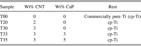
Three different materials were used to fabricate the coatings: (i) Ti6Al4V spherical, gas-atomized powder (ATI Powder Metals, Pennsylvania), (ii) multiwall CNTs (MWCNTs, Sigma-Aldrich, St. Louis, Missouri) having outer diameter <20 nm and length between 1 and 12 microns, and (iii) hydroxyapatite as calcium phosphate powder (Berkeley Advanced Biomaterials, Inc., California) with an average particle size of 600 nm. All compositions were premixed prior to loading into the hoppers for LENS™ fabrication. The LENS™ 750 system is equipped with two powder hoppers, allowing for in situ compositional variations during fabrication; however, all powders were premixed and loaded into a single powder feeder, increasing consistency throughout all fabrication processes. Premixed powders were ball milled with a powder-to-milling-media ratio of 2:1, as to give assistance to mixing the powders together creating a more homogeneous mixture, rather than milling the powders to a finer size. Ball milling was conducted for 6–10 h at low speeds, i.e., between 20 and 30 rpm. Prior to placing the premixed powders into the hoppers for 3D printing, powders were sieved using a −100/+325 mesh giving powder particle size range between 45 and 150 microns. Coatings were deposited on a 3 mm thick, commercially pure titanium (cp-Ti) substrate (President Titanium Co., Hanson, Massachusetts). A short-hand representing the different samples and their compositions are as follows: each sample is notated by the letter, T, followed by two numbers; the first number is the weight percentage of CNT’s in the coating and the second number is the weight percentage of CaP in the coating. Example: T30 has 3 wt% CNTs and 0 wt% CaP. Following this notation, five different compositions of coatings were fabricated: T00 (control), T20, T30, T33, and T35, as shown in Table I.
Compositions of different samples.

Successful deposition and fabrication of any type of coating using the LENS™ system requires the optimization of three main building parameters: laser power, powder feed rate, and scan speed. The coatings fabricated in this study were predominately Ti-based but small addition of CNTs and CaP significantly alter the required build parameters to achieve successful, dense, defect-free coatings. The parameters used to fabricate these coatings are laser power between 400 and 450 W, scan speeds between 6 and 12 mm/s, and powder feed rate between 8 and 12 g/min.
B. Microstructural and mechanical characterization
For microscopy, tribology, microhardness, and XRD, coatings were first mounted in a thermoset polymer and then ground with 120–1200 grit SiC grinding papers. The coatings were then polished to mirror finish using 1.0, 0.3, and 0.05 µm alumina powder suspended in DI water. Surfaces for microstructure imaging were etched using Kroll’s reagent (92 mL DI water, 6 mL nitric acid, 2 mL hydrofluoric acid); full submersion for 30 ± 4 s. Finally, coating surfaces were ultrasonically cleaned in pure ethanol for 10 min. Secondary electron images were captured using an FESEM (FEI Quanta 200, Hillsboro, Oregon). Phase analysis was obtained using XRD with a Cu Kα source, scanning 2θ values from 30 to 70°, with a step size of 0.05°, using a PANalytical X’pert Pro MPD X-ray diffractometer (Eindhoven, the Netherlands). Microhardness data were collected with a Vickers microhardness tester (HMV-2T, Shimadzu, Tokyo, Japan).
C. In vitro tribology
Tribological studies were carried out following ASTM G133 standards for linear reciprocating ball-on-disc tests. A 3 mm ϕ, alumina (Al2O3) ball was used, for a distance of 1000 m with a normal load of 7 N. The amplitude was set to 10 mm, creating wear tracks of total length 10 mm and the rate was set to 1200 mm/min.Reference Sahasrabudhe, Soderlind and Bandyopadhyay14,Reference Bandyopadhyay, Dittrick, Gualtieri, Wu and Bose16 Coatings were ultrasonically cleaned for 15 min with pure ethanol prior to each test, removing any unwanted surface particles. Tests were performed in a solution of Dulbecco’s modified eagle medium at room temperature. After each run, the solution was saved for ion-release studies. All solutions, post testing, had 5 mL of hydrochloric acid and 2 mL of nitric acid added to them to retain free ion-suspension in solution. Ion-release data were collected using inductively coupled plasma mass spectrometry (ICP-MS) (Agilent 4500, Santa Clara, California). Solutions had to be equally diluted to put recorded concentrations in the parts-per-billion (ppb) range, which is more accurate for the system used, compared with parts-per-million (ppm).
III. RESULTS
A. Microstructure and phase analysis
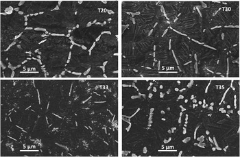
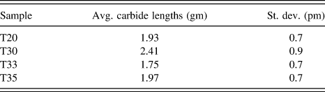
FESEM images of sample coatings can be seen in Fig. 1. A typical LENS™-processed Ti64 microstructure would possess a Widmanstatten pattern, consisting of interlacing acicular α-Ti with minor amounts of residual β-Ti along the edges of the acicular α-Ti.Reference Das, Balla, Basu, Manna, Kumar and Bandyopadhyay19 Looking at the microstructure of T20 and T30, acicular α-Ti with small amounts of β-Ti can be seen; however, the Widmanstatten pattern is not present as the interlacing of acicular α-Ti has been broken up by the formation of TiC particles, forming a quasi-equiaxed grain structure. The average lengths of carbides (n = 20) in each sample was calculated using ImageJ software (nih.gov) and tabulated in Table II. Samples T20 and T30 were found to have an average carbide length of 1.93 μm and 2.41 μm, respectively. It should be noted that these carbides are well incorporated into the titanium matrix, evenly distributed, with no voids or cracks; this is a direct result of the carbides being formed in situ during laser processing, from the addition of CNTs. With the addition of CaP, samples T33 and T35 were found to have average carbide lengths of 1.75 μm and 1.97 μm, respectively. In addition to the presence of carbides, T33 and T35 also have CaP particles dispersed throughout the microstructure. The CaP phase appears to be more clustered in T33, whereas the particles are more evenly dispersed in T35.
SE images of LENS™ deposited Ti6Al4V coatings with varying amounts of CNTs and CaP; all samples etched with Kroll’s reagent.

Average length of carbides in LENS™ deposited Ti6Al4V coatings containing CNTs and CaP (n = 20).

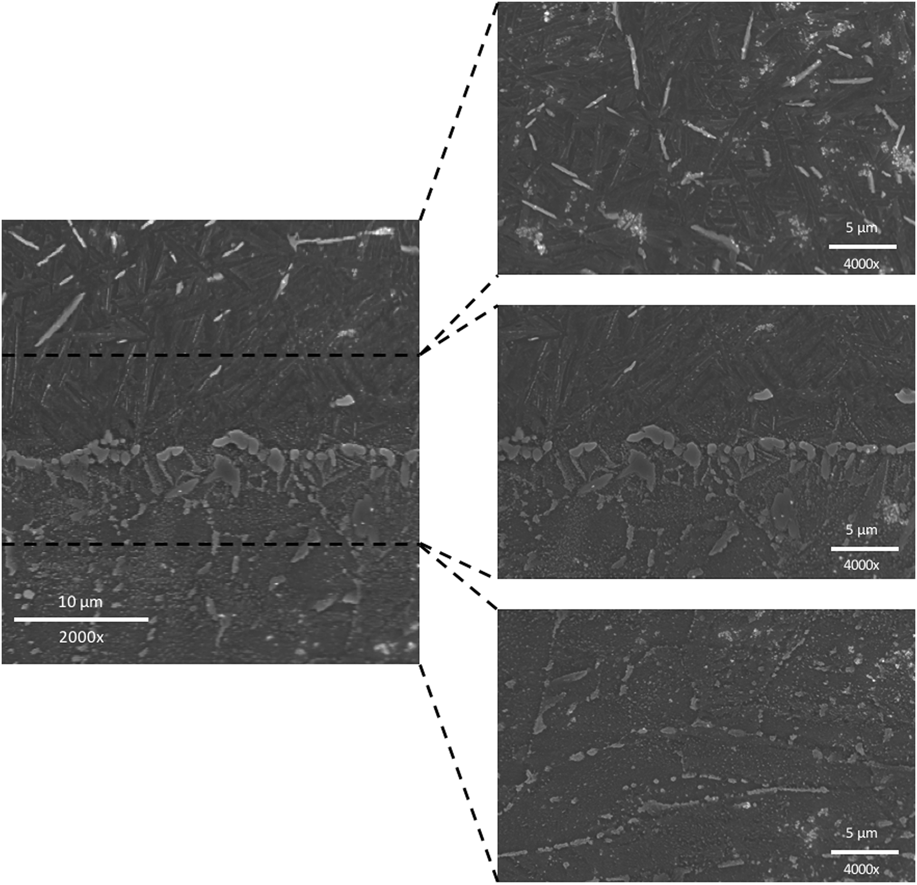
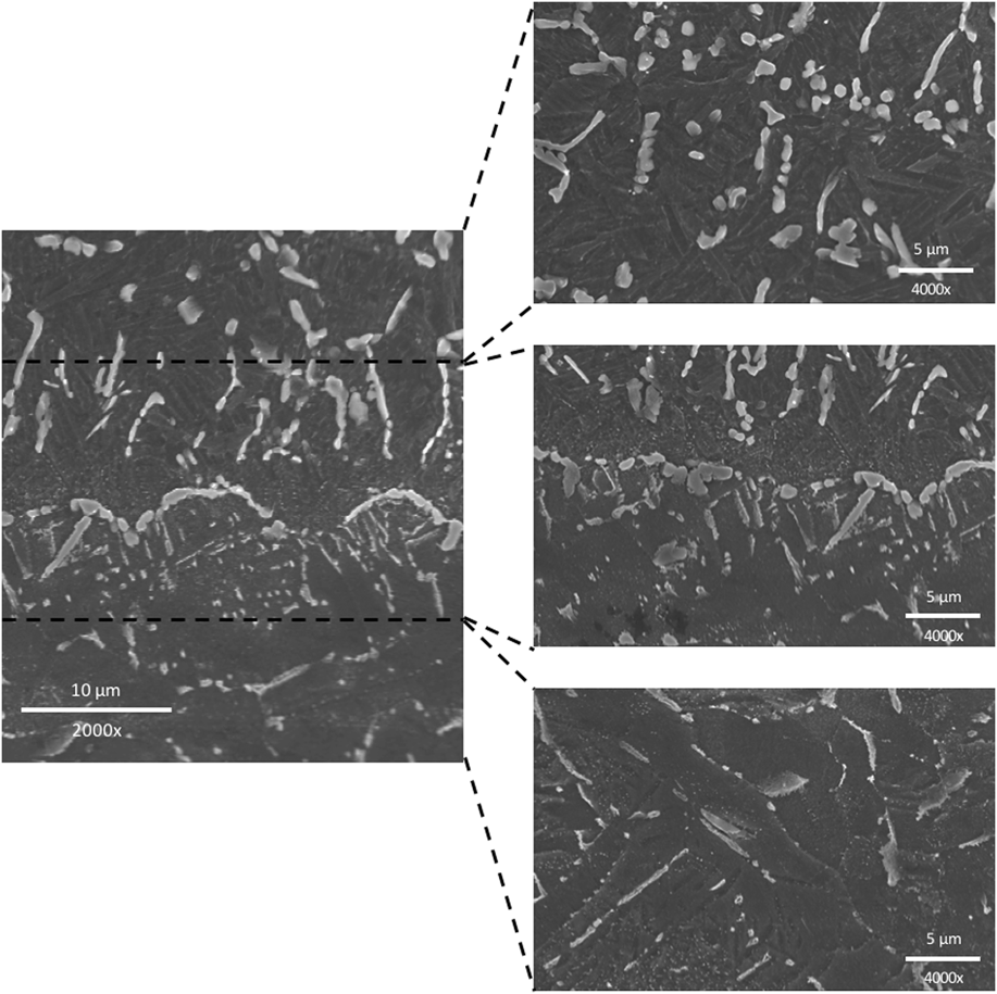
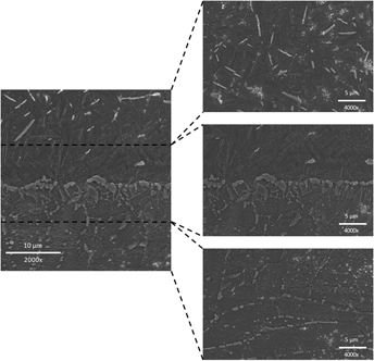
Representative images of coating interfaces for T33 and T35 can be seen in Figs. 2 and 3. FESEM images reveal that coatings are bonded completely with the cp-Ti substrate without any cracks or porosity. The heat affected zone (HAZ) is ∼50 µm, which is typical of the high cooling/heating rates of LENS™ processing.Reference Colwell, Hozack, Mesko, D’Antonio, Bierbaum, Capello, Jaffe and Mai8 Looking at the interface of T35 in Fig. 3, carbides near the interface are aligned perpendicular to the substrate surface and become unaligned with each layer of coating. Carbides aligned perpendicular to the substrate were formed during the deposition of the first layers when the cooling rates are significantly higher due to no residual heat from previously deposited layers. Here, carbides form in the opposite direction of the heat flow, resulting in carbide formation perpendicular to the substrate. After the first few layers have been deposited, residual heat builds up in the substrate, reducing the cooling rate of following layers. Carbide formation orientation is no longer dictated by the fast cooling rates. Similar observations were also made in a previous study.Reference Bose, Roy, Das and Bandyopadhyay11
SEM images of the microstructure at the interface of LENS™ deposited Ti6Al4V coating containing 3 wt% CNTs and 3 wt% CaP.

SEM images of the microstructure at the interface of LENS™ deposited Ti6Al4V coating containing 3 wt% CNTs and 5 wt% CaP.

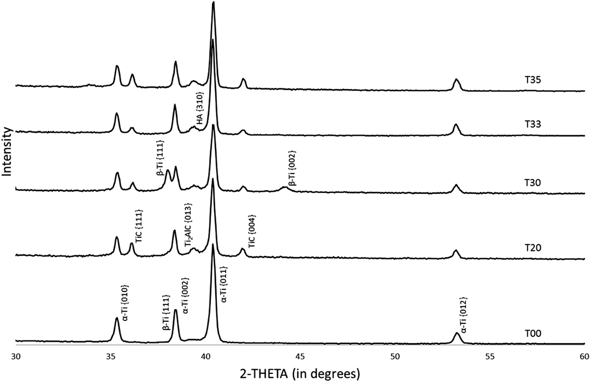
Phase analysis results from XRD can be seen in Fig. 4. The control sample T00 expresses predominantly α-Ti phases with small presence of β-Ti. With the introduction of CNTs, T20 shows similar phases as T00 with two additional phases, TiC and Ti2AlC. As the concentration of CNTs is increased in T30, a similar pattern as T20 can be seen with increased β-Ti peak intensity than any other sample. With the addition of CaP, both T33 and T35 express similar peaks as T20, along with a small hydroxyapatite peak, nearly overlapping with the Ti2AlC peak.
XRD results of LENS™ deposited Ti6Al4V coatings with CNTs and CaP. X-ray source was Cu Kα, scanning from 2θ values between 30 and 70° with a step size of 0.05°.

B. Hardness and wear properties
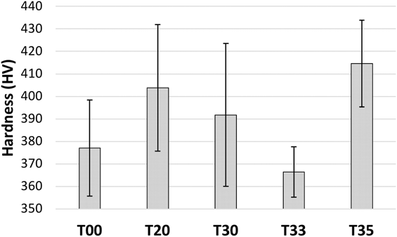
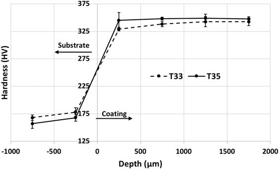
Microhardness results of the coatings can be seen in Fig. 5. Without any additives, LENS™-processed Ti64 (T00) was found to have an average surface hardness of 377 HV. Addition of 2 and 3 wt% CaP to Ti64, resulted in improved surface hardness values of 404 HV and 392 HV, respectively. Simultaneous additions of CNTs and CaP in samples T33 and T35, resulted in surface hardness values of 366 HV and 415 HV, respectively. Emphasizing the improvement in surface hardness obtaining in LENS™-processed coatings compared with the surface hardness of the substrate, Fig. 6 plots the hardness values of samples T33 and T35, as a function of the distance from the substrate/coating interface. The cpTi substrates for T33 and T35 were found to have surface hardness values averaging 168 HV and 157 HV, respectively. Approaching the interface, surface hardness values increased marginally, to 178 HV and 167 HV, respectively. At a distance of 250 μm into the coating, from the interface, surface hardness values were found to be 329 HV and 345 HV, respectively. Moving further into the coating, surface hardness values remain unchanged.
Vickers microhardness values for LENS™ deposited Ti6Al4V coatings containing CNTs and CaP. Load of 200 g and 15 s dwell time (n = 15).

Vickers microhardness values across the interface of samples T33 and T35 starting from the substrate and finishing in the LENS™-deposited coating.

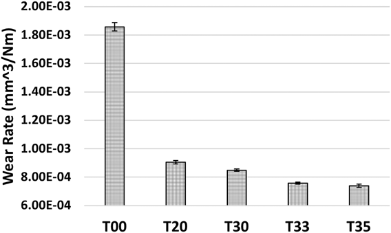
Wear rates of coatings can be seen in Fig. 7. T00 was found to have the highest wear rate of 1.86 × 10⁻³ mm3/Nm. Addition of CNTs in samples T20 and T30 resulted in wear rates of 9.06 × 10⁻⁴ mm3/Nm and 8.5 × 10⁻⁴ mm3/Nm, respectively. Simultaneous addition of CNTs and CaP in T33 and T35 resulted in wear rates of 7.58 × 10⁻⁴ mm3/Nm and 7.4 × 10⁻⁴ mm3/Nm, respectively. The most significant improvement is achieved by T20 with a 51% reduction in wear rates, compared with the control (T00). In reference to T20, T35 was found to have 18% reduction in wear rates.
Wear rates of LENS™ deposited Ti6Al4V coatings containing CNTs and CaPs (n = 3).

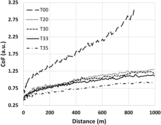
Mimicking the trend observed in the wear rates, the COF data can be seen in Fig. 8. T00 starts with a CoF of 0.74 and steadily rises to a maximum value of 3.10 at which point the test was automatically terminated, 150 m before the end of the full 1000 m run, as the wear limit of the testing setup was reached. T20 and T30 start with CoF values of 0.47 and 0.49, respectively, which initially increased quickly for the first 100 m, then slowly and steadily increase for the remainder of the test, finishing at values of 1.30 and 1.18, respectively. T33 was found to have a similar trend as T20 and T30, starting with a CoF of 0.40 and initially increasing quickly for the first 100 m. However, the CoF of T33 increased steadily between 100 and 800 m, at which point the CoF remained the same for the remaining 200 m of the test. T35 showed a higher initial CoF increase but not as significant compared to the other coatings. T35 started with a CoF of 0.40 and finished at a value of 0.90.
COF plots of LENS™ deposited Ti6Al4V coatings containing CNTs and CaPs (n = 3).

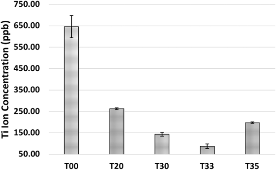
Continuing a similar trend displayed by both wear rates and CoF values, the ion-release data can be seen in Fig. 9. T00 was found to have the highest Ti-ion release at a value of 646 ppb. Addition of CNTs in T20 and T30 resulted in Ti-ion release concentrations of 263 ppb and 144 ppb, respectively. Simultaneous additions of CNTs and CaP in T33 and T35 resulted in Ti-ion release concentrations of 87.4 ppb and 197 ppb, respectively. T20 and T30 resulted in 59 and 78% reductions in Ti-ion release, with respect to T00. T33 resulted in 86% decrease in Ti-ion release compared to T00.
Titanium-ion release concentrations from LENS™ deposited coatings containing varying amounts of CNTs and CaPs. Values were obtained using ICP-MS.

IV. DISCUSSION
A. Microstructure and phase analysis
Looking at T20 and T30, the use of CNTs as a carbon source for in situ carbide formation during LENS™ processing resulted in the formation of TiC particles with average lengths of 1.93 μm and 2.41 μm, respectively. With an additional 1 wt% of CNTs, T30 sees a 25% increase in average carbide length compared to T20. Regardless of size differences, both coatings show the carbides to be evenly distributed throughout the Ti matrix, without any voids, porosity, or cracking. The presence of carbides in the Ti microstructure eliminated the typical Widmanstatten pattern seen in LENS™-processed Ti64; however, acicular α-Ti grains can still be seen with minor amounts of residual β-Ti along the edges of the α-Ti grains. The β-Ti phase is distinguished in the scanning electron microscopy (SEM) images of Fig. 1 by the lighter color that forms around the edges of the darker, acicular α-Ti grains. T30 appears to have significantly thicker bright, β-Ti regions surrounding the acicular grains, i.e., T30 has a greater amount of retained β-Ti. This observation aligns well with the phase analysis from XRD. T30 is the only sample that has β-Ti peaks visible when plotting 2θ values from 30 to 60°. This could also explain why a reduction in surface hardness is observed between T20 and T30. In terms of mechanical properties, an increase in residual β-Ti is sought if there is a desire to increase the ductility of the titanium alloy. The cubic structure of β-Ti has more slip planes than the hexagonal close-packed structure of α-Ti, giving β-Ti a more ductile nature.Reference Das, Balla, Basu, Manna, Kumar and Bandyopadhyay19 Simultaneous addition of CNTs and CaP in T33 and T35 result in a predominantly acicular α-Ti matrix with the presence of both carbides and CaP particles. The carbides in T33 are evenly distributed throughout the matrix but the CaP particles are distributed in clusters of varying sizes. The CaP appears to be more evenly distributed in the matrix of T35. T35 was found to have the highest surface hardness but only by 2.7% higher than that of T20. Furthermore, the surface hardness of T33 is the lowest, at a value of 366 HV.
Studies using carbide precursors such as TiC found microstructures consisting of two distinct carbide particles. The first being carbide particles that were either never melted or only partially sintered during processing, resulting in particle sizes as large as 90 µm. The second type of carbides observed were those that were completely melted and resolidified, resulting in fine particles ranging in sizes from 1 to 4 µm.Reference Colwell, Hozack, Mesko, D’Antonio, Bierbaum, Capello, Jaffe and Mai8 By using CNTs as a carbon source for in situ carbide formation, no large unsintered particles can be seen in the microstructure. Rather, carbide formation by in situ processing resulted in only small carbides evenly distributed throughout the matrix.
SEM images of the interfaces of T33 and T35 can be seen in Figs. 2 and 3, respectively. It can be seen from these images that the interface is free from any voids, cracks, or porosity. Coatings bonded to the substrate, completely, with a HAZ of roughly 50 μm, are typical of LENS™ processing.Reference Bandyopadhyay, Dittrick, Gualtieri, Wu and Bose16,Reference Sahasrabudhe, Bose and Bandyopadhyay18 This narrow HAZ is also represented by the surface hardness values taken along the interface of T33 and T35, plotted in Fig. 6.
Coming back to the phase analysis data from XRD, shown in Fig. 4, T00 has phases typical of LENS™-processed Ti64; i.e., α-Ti and β-Ti. With the addition of 2 wt% CNTs in T20, two additional phases were found in the coating: titanium carbide (TiC) and titanium aluminum carbide (Ti2AlC). Due to high temperatures during laser processing, the CNTs break down into carbon and combine with Ti and Al forming TiC and Ti2AlC particles. With 3 wt% CNTs in T30, no new phases are found; however, as noted earlier, the β-Ti peaks are much larger, signifying an increased amount of residual β-Ti in T30 coating. Carbon itself is one of the three known interstitial-type α-Ti phase stabilizers (α-stabilizer), along with oxygen and nitrogen. As such, the addition of carbon should reduce the potential for retained β-Ti. However, the carbon is not positioned in interstitial sites; rather, it is reacting with Ti and Al forming carbides. Particularly, the formation of Ti2AlC offers highly probable reasoning for the higher amounts of residual β-Ti in T30 coating. Aluminum is one of the three known substitutional-type α-stabilizers, along with gallium and germanium. Substitutional α-stabilizers are elements that are more soluble in the hexagonal α-Ti phase, raising both the α- and β-transus temperatures in titanium alloys, resulting in the stabilization of the α phase. During laser processing of Ti64 and CNTs, the formation of Ti2AlC is reducing the amount of aluminum that would normally stabilize the α-phase. Vanadium, which is one of the four known β-stabilizers, remains unaffected by the addition of CNTs. Therefore, CNTs reduce α-stabilizing aluminum content in Ti64 with the formation of Ti2AlC, while β-stabilizing vanadium is unaffected, resulting in a microstructure with a greater amount of retained β-Ti. With the addition of 3 and 5 wt% CaP in T33 and T35, a hydroxyapatite (HA) phase can be seen, which is almost masked by the Ti2AlC peak. It should be noted that even with the same CNT content as T30, T33, and T35 have small β-Ti peaks, as seen in T00 and T20. CaP appears to not react with Ti64 nor CNTs, with no additional phases being detected in T33 and T35, besides the HA peak, itself. XRD results overall align well with SEM images, where only α-Ti, β-Ti, carbides, and HA particles are seen.
B. Hardness and wear properties
Values for the surface hardness of coatings can be seen in Fig. 5. T00 was found to have an average surface hardness of 377 HV. This value is higher than typical hardness values for Ti64 (350 HV), but this is expected as the inherent nature of LENS™ processing results in refined grain structures, resulting in higher mechanical properties for LENS™-processed Ti64 compared to annealed, cold-rolled Ti64.Reference Bose, Roy, Das and Bandyopadhyay11 With the addition of 2 wt% CNTs in T20, the average surface hardness increases to 404 HV. This increase in hardness is attributed to the in situ formation of carbides and similar results have been reported in the literature.Reference Das, Balla, Basu, Manna, Kumar and Bandyopadhyay19 T30 was found to have an average surface hardness of 392 HV. Recalling that T30 was found to have a higher amount of retained β-Ti, which is believed to be the reason for this drop, T35 coating was found to have the highest average surface hardness of 415 HV.
Tribological characteristics of coatings were investigated and characterized by wear rates, COF, ion-release, and SEM images of wear tracks. Wear rates, shown in Fig. 7, show the highest wear rates in T00 at a value of 1.86 × 10⁻³ mm3/Nm. With an addition of 2 wt% CNTs in T20, wear rates are reduced by 51% at a value of 9.06 × 10⁻⁴ mm3/Nm. With an additional 1 wt% of CNTs in T30, wear rates are further reduced to 8.5 × 10⁻⁴, a 6% reduction. With a 51% decrease in wear rates in T20 and only a 6% reduction in T30, it is apparent that significant improvements in wear rates can be achieved with small amounts of CNTs (2 wt%). Simultaneous additions of CNTs and CaP in T33 and T35 resulted in the lowest wear rates at values of 7.58 × 10⁻⁴ mm3/Nm and 7.40 × 10⁻⁴ mm3/Nm, respectively. Although T33 and T35 had the lowest wear rates, compared to T30, the wear rates are only reduced by 11 and 13%, respectively.
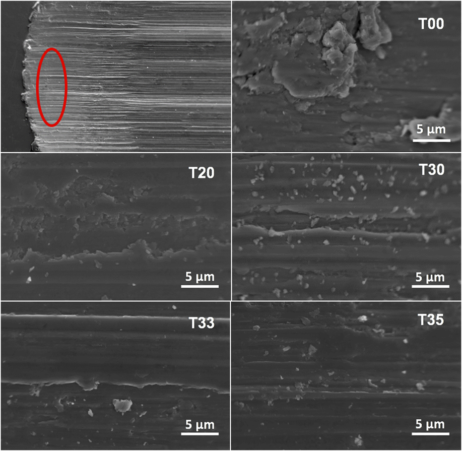
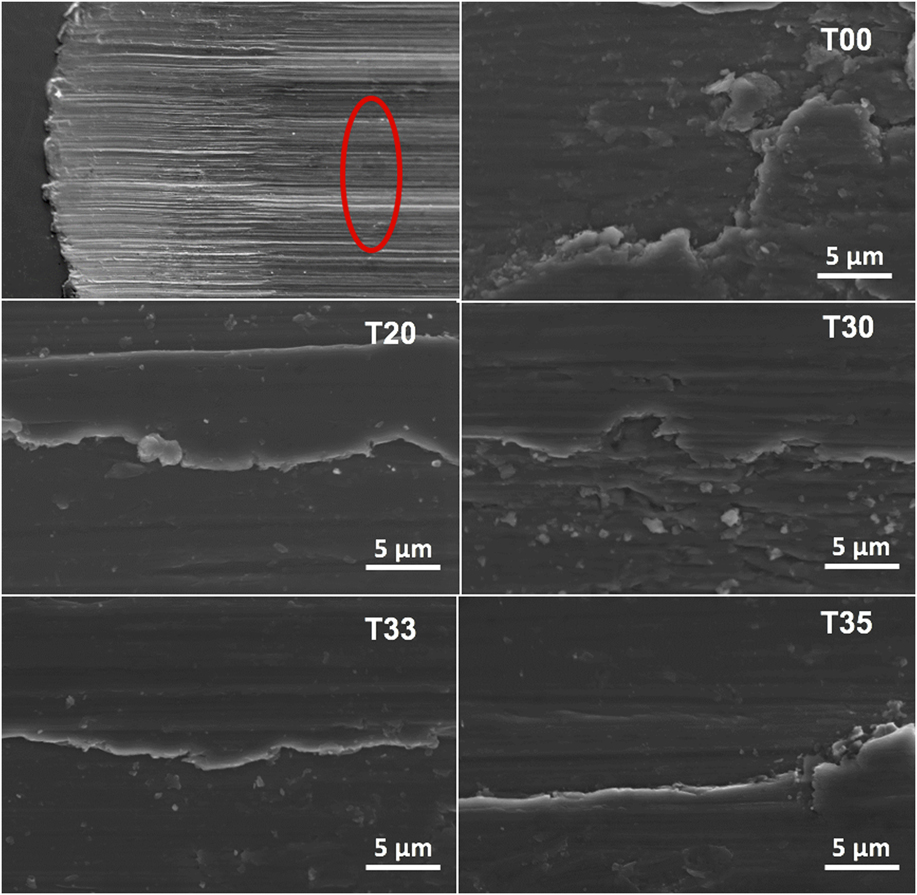
Looking at the CoF data in Fig. 8, the results align well with the trend found in the wear rate data. T00 starts at a value of 0.70, which then steadily increases to a value of 3.1 where the test was automatically stopped due reaching the wear limits. T00 also showed the highest Ti-ion release at a value of 646 ppb. Furthermore, SEM images of the wear tracks of T00 show a great amount of pitting and ductile wear debris. With the addition of CNTs in T20 and T30, COF reduces significantly, with coatings reaching a maximum value of 1.30 and 1.24, respectively, by the end of the test. Ti-ion release values for T20 and T30 were found to be 263 ppb and 144 ppb, respectively. Compared to T00, T20 and T30 have a 59 and 78% reduction, respectively, in Ti-ion release. Wear track images of T20 and T30 reveal fracture surfaces of a brittle nature. It can also be observed that instead of localized, ductile pitting, T20 and T30 degrade in a manner forming long, planar scales, aligned in the direction of the wear test. With simultaneous additions of CNTs and CaP in T33 and T35, the lowest COFs were observed with final values of 1.11 and 0.90, respectively. Again, these data correlate well with the wear rate data with T33 and T35 having lowest wear rates. The lowest Ti-ion release was achieved in T33 with a value of 87.4 ppb, following trends in wear and COF data. However, T35 was found to have a Ti-ion release concentration of 197 ppb. Furthermore, SEM images of the wear tracks of T33 and T35—shown in Figs. 10 and 11—express the absence of any pitting, and the presence of long, smooth sheets suggesting the presence and formation of a CaP-based tribofilm. In addition, the COF for T33 and T35 remains statistically the same for the final 100 m of the test, suggesting the formation of a protective tribofilm, reducing frictional forces, and resulting in reduced wear rates and Ti-ion release concentrations.
SEM images at the tip of the wear tracks on LENS™ deposited Ti6Al4V coatings containing varying amount of CNTs and CaPs.

SEM images in the body of wear tracks on LENS™ deposited Ti6Al4V coatings containing varying amounts of CNTs and CaPs.

V. CONCLUSIONS
Seeking to improve the wear resistance of Ti64 for application in load-bearing articulating surfaces, this study investigated the effects of simultaneous additions of CNTs and CaPs in Ti64 using laser-based additive manufacturing. The results show that Ti64 coatings containing both CNTs and CaPs deposited using LENS™ can be successfully 3D-printed onto cpTi, with complete bonding at the interface and no voids, cracks, or porosity throughout the coating. In addition, these coatings were found to have higher surface hardness, reduced wear rates, lower COFs, and reduced Ti-ion release concentrations. Ti64 coatings containing 3 wt% CNTs and 5 wt% CaPs were found to have a 10% increase in surface hardness, 60% reduced wear rates, 70% reduction in COF, and 69% reduced ion-release, compared to LENS™-processed Ti64.
ACKNOWLEDGMENTS
Financial supports from the National Science Foundation under the Grant Nos. CMMI 1538851 and JCATI (Seattle, WA) are acknowledged.