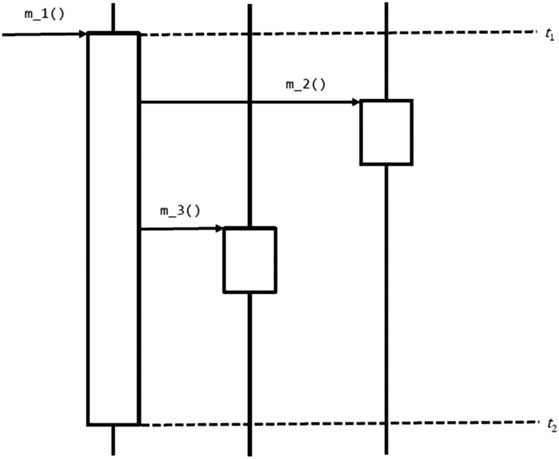


1 Introduction
The Unified Modeling Language (UML) has become the de facto standard for object-oriented modeling (Sommerville, Reference Sommerville2004). During the software system development lifecycle, different but related UML models are developed to represent different views of the system. For instance, use cases capture the externally visible services of the system to be built, class diagrams express the system’s static structure, and sequence diagrams represent the dynamic interactions within the system (Object Management Group, 2010). Every use case should be realizable by a sequence diagram. Sequence diagrams mainly describe the communication among sets of objects. Such objects are classified in class diagrams. Objects communicate by sending messages to each other. Sequence diagrams are one of those models that can be difficult to create and creating them manually is an error-prone process. The results of the experiments by Yue et al. (Reference Yue, Briand and Labiche2013) support this observation. In their experiments, 4th-year undergraduate trained students failed to create 50% of the required messages. Out of the created messages, 25% were inconsistent with the reference diagrams. Therefore, automating that process would be quite helpful. However, to the best of our knowledge, the problem of automatic sequence diagrams generation has not received adequate attention from researchers yet. This is apparent from our literature survey discussed in Section 3. Therefore, an approach that focuses on automatic sequence diagrams generation is worth investigating.
In this paper, we propose an approach to combine Artificial Intelligence (AI) action planning techniques and Design by Contract (DbC) (Meyer, Reference Meyer1997) concepts to automatically generate sequence diagrams from use cases and class diagrams. The hypothesis being tested in this research is that by enforcing DbC in the specification of the use cases and the class diagram, the problem of generating the sequence diagrams can be treated as an action planning problem. This hypothesis defines the experimental context of our research as per Kitchenham et al.’s (2002) guidelines.
Automatic sequence diagrams generation is of paramount importance within the context of the representation framework view-points requirements analysis (Rumbaugh et al., 1991; Sommerville, Reference Sommerville2004). This technique is a rigorous requirements analysis technique where viewpoints represent particular types of system model. These types of models are developed independently and compared to discover requirements that would be missed using a single representation. For example, the sequence diagrams are used to double check the consistency between the conceptual class diagram (i.e. structural view) and the use cases (i.e. functional view). Sequence diagrams are usually derived from these two types of models, and then used in the design phase as a starting point for setting up the architecture and component designs. This is in contrast to agile-like UML-based software development techniques which are at the same time iterative and incremental, for example, the Rational Unified Process, where class diagrams and sequences diagrams are derived from use cases in a linear path. If a requirement is missed in one type of model, it will be missed in later types of model.
Through the formalism it offers, DbC provides a good tool for rigorous requirements engineering. The support for DbC in Computer-Aided Software Engineering (CASE) tools and programming frameworks is increasing. For example, Enterprise Architect 8 allows the user to specify pre-conditions and post-conditions for individual methods (usually referred to as operations in UML) in a class diagram, albeit rather in a form of informal description. This opens up the possibility for the proposed work to be implemented as a plug-in for such CASE tools. Also, support for code contracts is now a core feature of the .NET Framework 4 (What’s New in the .NET Framework 4, 2014). These observations suggest that more and more software developers and professionals are adopting DbC as they realize its practical benefits.
Since—to the best of our knowledge—there were no published works on applying AI planning to the problem of UML sequence diagram generation when DbC is used to develop the use cases and class diagrams, the research effort presented in this paper had two main objectives:
1. To show that the core activity of sequence diagram generation (i.e. determining the sequence of message passing) can indeed be treated as a planning problem and solved as such.
2. To identify the issues that need to be addressed and the problems that need to be solved to advance the application of AI planning to the domain of sequence diagram generation.
To achieve the first objective, the correspondence between automated action planning and message-passing planning (or simply ‘message planning’) is established based on the conceptual model of state-transition systems used in AI planning (Ghallab et al., Reference Ghallab, Nau and Traverso2004; Russell & Norvig, Reference Russell and Norvig2009). In doing so, we discovered differences between action planning and message planning that makes adapting existing action planners to sequence diagrams generation difficult. Based on those differences, a software tool for planning messages in sequence diagrams, Communiqué, was developed. Using Communiqué, it was empirically shown that even with a simple conceptual model of restricted state-transition systems, determining the sequence of messages in sequence diagrams can be treated as a planning problem and can be solved using state-space search techniques. With the increasing support for DbC in modeling tools and programming frameworks, this approach should be able help in improving the quality of the software models as well as analysts and designers productivity.
This paper is organized as follows. Section 2 presents the background necessary to understand the rest of the paper. Section 3 presents a survey of the relevant literature and evaluates related approaches. The main idea of using AI planning and DbC to plan messages in sequence diagrams is explained and presented in Section 4. The same section also discusses the details of Communiqué, the software library that we implemented for that purpose. Section 5 gives the necessary technical; details regarding the implementation of Communiqué. Section 6 contains the details of the experiments that we carried out to evaluate the proposed approach and its implementation. Section 7 discusses the validity of the results and the limitations of the work. Finally, Section 8 concludes the paper by discussing the contributions and future work.
2 Background
This section provides the necessary background needed to understand the rest of this paper. It covers the three components of the approach: UML Models (including Use Cases, Class Diagrams, and Sequence Diagrams), DbC, and AI planning. A reader interested in knowing more about a particular topic under these three areas is encouraged to consult the relevant references used in this section.
2.1 Modeling with UML
As Bruegge and Dutoit (Reference Bruegge and Dutoit2010) note, the concept of use case was made popular by Jacobson et al. (Reference Jacobson, Christerson, Jonsson and Overgaard2004) in Object-Oriented Software Engineering: A Use Case Driven Approach. Use cases of a software system represent its functionality. They capture the general sequences of interactions between actors, which are entities external to the system, and the system itself. Each use case describes how an actor uses the system to accomplish a particular goal.
Use cases are modeled in UML by a Use Case Diagram along with textual descriptions. Use case descriptions are typically written in natural language to facilitate communication with the client and the users of the system. There is no standard way to describe use cases textually and, accordingly, there is a number of different use case templates available in the literature. Nevertheless, use case templates generally contain the following main fields:
∙ Use case name or title.
∙ Participating actors, including the actor that initiates the use case.
∙ Pre-conditions (or entry conditions; Bruegge & Dutoit, Reference Bruegge and Dutoit2010), which are the conditions that must be ensured before initiating the use case.
∙ Flow of events, which is the sequence of interactions of the use case. A use case may also have alternative flows of events.
∙ Post-conditions (or exit conditions; Bruegge & Dutoit, Reference Bruegge and Dutoit2010), which are the conditions that will be true after the completion of the use case.
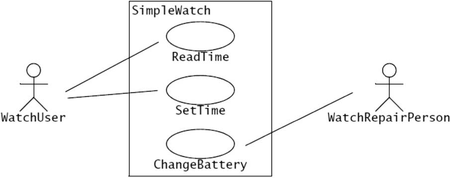
As an example, Figure 1 depicts a UML use case diagram describing the functionality of a simple watch (Bruegge & Dutoit, Reference Bruegge and Dutoit2010). The WatchUser actor may either consult the time on the watch (with the ReadTime use case) or set the time (with the SetTime use case). However, only the WatchRepairPerson actor can change the battery of the watch (with the ChangeBattery use case). Actors are represented with stick figures, use cases with ovals, and the boundary of the system with a box enclosing the use cases. Each use case is further described in terms of its pre-conditions, flow of events, and post-conditions.
A Unified Modeling Language use case diagram describing the functionality of a simple watch (Bruegge & Dutoit, Reference Bruegge and Dutoit2010)

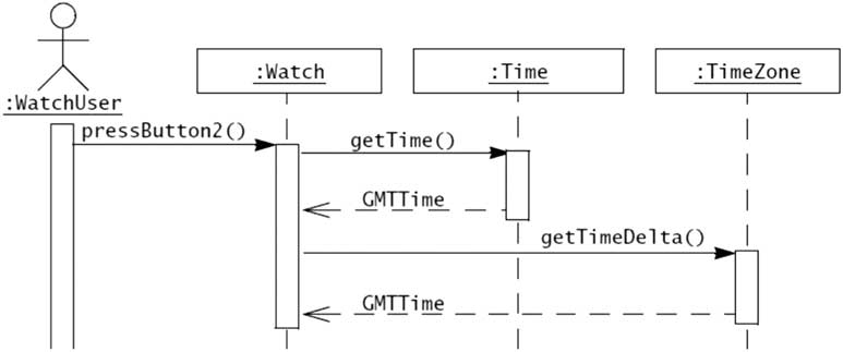
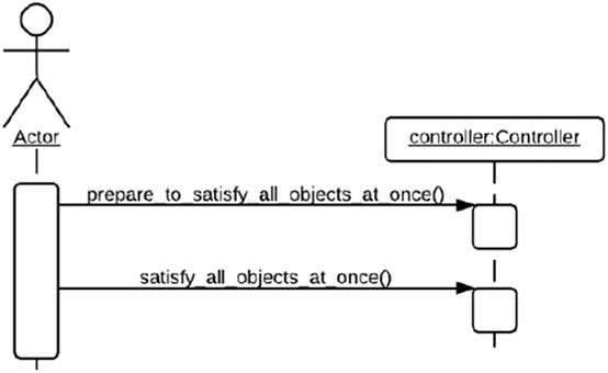
Sequence diagrams represent another UML model that shows how objects in the system interact to offer the functionality manifested in the form of use cases (Object Management Group, 2010). A sequence diagram shows the interactions between objects arranged in time order. It depicts the functionality of use case by showing objects and messages that are passed between these objects in a use case. Objects communicate by sending messages to each other. An object can request the execution of an operation on a different object by sending it a message, which is composed of a name and arguments (if any) (Bruegge & Dutoit, Reference Bruegge and Dutoit2010). Sequence diagrams describe interactions between objects by focusing on the sequence of messages that are exchanged between the objects. In these diagrams, objects involved in an interaction are presented horizontally, while time is presented vertically. If the sequence diagram includes an actor that initiates the interaction, the actor is shown in the left-most column. Vertical lines, which are called lifelines, represent the objects. Horizontal arrows between the lifelines represent messages exchanged between the objects. Vertical bars on the lifelines represent activations (i.e. execution of operations). Figure 2 depicts examples of UML sequence diagram of message passing. The Watch object sends the getTime() message to a Time object to query the current Greenwich time. It then sends the getTimeDelta() message to a TimeZone object to query the difference to add to the Greenwich time. The dashed arrows represent the replies (i.e. message results that are sent back to the sender; the dashed line is optional as it is understood from the activation bar) (Bruegge & Dutoit, Reference Bruegge and Dutoit2010).
Examples of Unified Modeling Language sequence diagram of message passing

In our work, we essentially consider the description of use case, more specifically, the use case pre-conditions and post-conditions, rather than the use case diagram.
2.2 DbC
Meyer (Reference Meyer1997) coined the term DbC where routines are semantically specified using pre-conditions and post-conditions. A pre-condition is the condition that must be ensured before calling the routine if it is to function properly; a post-condition is the state that the routine guarantees yielding assuming that it was called with the pre-condition satisfied. The pre-conditions and post-conditions of a routine (e.g. an operation of an object) define a contract that binds it and its callers. In this contract, the routine is the supplier of a service and its callers are the clients. The contract defines obligations and benefits for the supplier and its clients: the pre-condition is a benefit for the routine and an obligation for the callers; the post-condition is an obligation for the routine and a benefit for the callers.
As an example, consider the pop() routine of a stack class that can store objects of type T and that has a limited capacity. The class developer may specify that this routine should not be called on an empty stack. This constraint constitutes the pre-condition of the routine. If the routine is called on a nonempty stack, it will remove the top element. By doing so, it will decrease the number of elements by one and ensure that the stack is not full even if it was so before the call. These guarantees constitute the post-conditions of the routine. Adopting the notation Meyer (Reference Meyer1997) uses in his book, which uses a require clause to express pre-conditions and an ensure clause to express post-conditions, this constraint can be expressed as a contract of the routine as follows:
pop(): T
require
not empty
do
…
ensure
not full
count=old count - 1
end
DbC can be applied to UML models by using the Object Constraint Language (OCL) (Warmer & Kleppe, Reference Warmer and Kleppe2003). OCL is not an action language; it is rather a specification language for UML. UML model elements are annotated with OCL constraints to ensure their proper usage, and the validity of the whole model. They can be used to express pre-conditions, post-conditions, invariants, guard conditions, and results of operations. An OCL constraint typically consists of two parts: the context and a set of OCL expressions. As an OCL constraint highly depends upon which model element is constrained, this information is specified by the first part of the OCL constraint, that is, its context. An OCL context can either be a class, one of its attributes, or one of its operations, and it can be referenced in the constraint’s body by the keyword self. The second part of an OCL constraint consists of a set of OCL expressions, each of which consists of a type, name, and body. The frequently used expression types include inv, which is used when the body contains a condition that must be met by all instances of a class; pre, which is used when the body contains a condition that must be true before executing an operation, that is a pre-condition; and post, which is used when the body contains a condition that states what should be true about the state of the system and the changes that occurred after executing an operation, that is a post-condition.
As an example, consider the pop() routine used above. Assuming that the stack class has the two Boolean routines isEmpty() and isFull(), along with the integer attribute count, the pre-conditions and post-conditions of the pop() routine can be expressed in OCL as follows:
context Stack::pop(): T
pre:not self.isEmpty()
post: not self.isFull() and
self.count=self.count@pre - 1
2.3 AI planning
In the field of AI, planning refers to finding a sequence of actions that can achieve a certain goal (Ghallab et al., Reference Ghallab, Nau and Traverso2004; Russell & Norvig, Reference Russell and Norvig2009). The conceptual model that underlies many planning approaches is the general model of state-transition systems. In particular, classical planning relies on the model of restricted state-transition systems. A restricted state-transition system is a general state transition system with some restrictive assumptions (Ghallab et al., Reference Ghallab, Nau and Traverso2004). For example, the system has a finite set of states, the system is fully observable, the system is deterministic, etc. A restricted state-transition system is a triple Σ=(S, A, γ), where:
∙ S={s 1, s 2,…} is a finite set of states.
∙ A={a 1, a 2,…} is a finite set of actions.
∙ γ : S×A→S is a state transition function.
A state-transition system can be represented by a directed graph whose vertices are the states in S and whose edges are the state transitions, where there is an edge labeled a from s to ś ’ if ś= γ(s, a).
A planning problem for a restricted state-transition system Σ is defined as a triple P=(Σ, s 0, S g ), where:
∙ s 0 ∈ S is an initial state.
∙ S g ⊆ S is a set of goal states.
Based on this conceptual model, and as Figure 3 illustrates, solving a planning problem means finding a sequence of actions that, starting from a particular state, will achieve a certain goal. More formally, solving a planning problem P consists of finding a sequence of actions (a 1, a 2,…, a k ) that corresponds to a sequence of state transitions (s 0, s 1,…, s k ) such that s 1=γ(s 0, a 1),…, s k =γ(s k−1, a k ) and s k ∈ S g .
A solution to a planning problem as a sequence of actions and state transitions

Automated planners need a description of the problem to be solved, that is P. In most—if not all—real-world domains, it would be unrealistic to use a description that explicitly enumerates all the states and state transitions. Instead, the description should make it easy to compute states and state transitions when they are needed. There is a number of different representations that can be used to describe a planning problem. Some of these representations are (Ghallab et al., Reference Ghallab, Nau and Traverso2004):
1. Set-theoretic representation, in which each state is a set of proposition symbols, and each action is an expression that specify which propositions must belong to the state for the action to be applicable and which propositions the action will add or remove from the state to create a new state.
2. Classical representation, which generalizes the set-theoretic representation by using first-order logic.
3. State-variable representation, in which each state is a tuple of values of state variables {x 1, … ,x n }, and each action is a partial function mapping this tuple into another tuple of values of the state variables.
As Ghallab et al. (Reference Ghallab, Nau and Traverso2004) note, the classical representation is credited to the Stanford Research Institute Problem Solver (STRIPS) (Fikes & Nilsson, Reference Fikes and Nilsson1971), one of the early automated planners. As enhancement to the STRIPS’ representation, the Action Description Language (ADL) (Pednault, Reference Pednault1989; Pednault, Reference Pednault1994), which was introduced later, presented a trade-off between the expressiveness of general logical formalisms and the computation complexity of reasoning with that representation. Several automated planners used representations close to the ADL’s to offer extensions to the classical representation. Extensions range from simple syntactical extensions to disjunctive pre-conditions and extended goals. Many of such extensions were then implemented in the Planning Domain Definition Language (PDDL) (McDermott et al., Reference McDermott, Ghallab, Howe, Knoblock, Ram, Veloso, Weld and Wilkins1998). In the three representations listed earlier, actions are essentially specified in the same way: by using pre-conditions and effects. Pre-conditions are the conditions that must be true in a state for the action to be applicable to that particular state. Effects are the changes that the action makes to the state it is applied to. For example, let us revisit the pop() routine that was used in Section 2.2. Treating pop as an action that takes a stack as a parameter, and assuming that count is a function that computes the number of items in a stack, the pop action can be specified in PDDL as follows:
(:action pop
:parameters (?s - Stack)
:pre-condition (>(count ?s) 0)
:effect (decrease (count ?s) 1)
)
The classical and state-variable representations are equivalent in their expressiveness (Ghallab et al., Reference Ghallab, Nau and Traverso2004). That is, a planning problem expressed in one of these two representations can be translated, with at most a linear increase in size, into the other. On the other hand, and although the three representations can represent the same set of planning domains, a set-theoretic representation may take exponentially more space than the equivalent classical and state-variable representations.
Using the conceptual model of state-transition systems mentioned above, an automated planner can search the space of states looking for a sequence of actions that will connect, through state transitions, the initial state s 0 with a goal state sg ∈ Sg . This is known as state-space search. Using pre-conditions and effects, the planner can move in the search space in either direction: progressing forward from the initial state or regressing backward from the goal. The former is known as forward search, while the latter is known as backward search.
Planning with state-space search is one form of total-order planning. There is also the more flexible partial-order planning, in which a planner generates several subplans for several subgoals independently, and then combines those subplans (Ghallab et al., Reference Ghallab, Nau and Traverso2004). Other approaches also exist. Interested reader may refer to the excellent discussions of planning techniques by Ghallab et al. (Reference Ghallab, Nau and Traverso2004) and Russell and Norvig (Reference Russell and Norvig2009).
2.4 The correspondence between AI planning and DbC
Using DbC in the specification of the use cases and the class diagram, the problem of generating sequence diagrams can be treated as a planning problem. As Sulaiman and Ahmed (Reference Sulaiman and Ahmed2012) pointed out, in both cases, and despite some differences in terminology, the same building blocks are present.
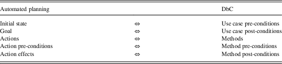
In DbC, routines are semantically specified using pre-conditions and post-conditions, where pre-conditions are the conditions that must be ensured before calling the routine if it is to function properly, and post-conditions specify the state that the routine guarantees yielding if it was called with the pre-conditions satisfied. On the other hand, actions in AI planning are essentially specified by using pre-conditions and effects, where pre-conditions are the conditions that must be true in a state for the action to be applicable to that particular state, and effects are the changes that the action makes to the state it is applied to. So, methods and their pre-conditions and post-conditions in DbC correspond to actions and their pre-conditions and effects in AI planning.
Furthermore, use cases usually have pre-conditions, which are the conditions that must be ensured before initiating the use case, and post-conditions, which are the conditions that will be true after the completion of the use case. One can look at the pre-conditions and post-conditions of a use case as the specification of the initial state and a goal state of a planning problem.
This correspondence between AI planning and DbC, which Table 1 summarizes, opens the door to treating the core activity of sequence diagram generation, which is determining the sequence of messages exchanged between the objects involved in the interaction, as a planning problem.
Correspondence between Artificial Intelligence planning and Design by Contract (DbC) (Sulaiman & Ahmed, Reference Sulaiman and Ahmed2012)

3 Literature survey
As per the guidelines of Kitchenham et al.’s (2002) for the experimental context, in this section we present related work. The literature surveyed can be divided into two general groups: works that focused on automatically generating models, and works that connected AI planning on one hand and requirements and knowledge engineering on the other. The following two sections will discuss each of these groups separately.
3.1 Automatic model generation
Yue et al. (Reference Yue, Briand and Labiche2011) present a systematic review that focuses on transforming textual requirements to analysis models in the context of model-driven development. They review 16 approaches and evaluate their capabilities, support for establishing traceability links, degree of automation, efficiency, and completeness. To do that, they design a conceptual framework and derive a set of evaluation criteria from it. The authors observe that none of the existing approaches is easily applicable on real systems, has less than two transformation steps, or is able to automatically generate a complete and consistent analysis model. They suggest a pattern for future approaches that consists of using reasonable restrictions on natural language, an automatic requirements preprocessing technique, and one intermediate model to transform a use case model (UCMod) into a UML model that comprises structural and behavioral aspects. They also suggest some quality characteristics for transformation approaches, like usability, efficiency, scalability, and extensibility.
Yue et al. (Reference Yue, Briand and Labiche2013) followed their own suggestion and proposed a technique to automatically derive analysis models, including sequence diagrams, from use cases while maintaining traceability links. Requirements must first be defined manually using the Restricted Use Case Modeling (RUCM) approach, which the authors proposed in an earlier work (Yue et al., Reference Yue, Briand and Labiche2009). The result of RUCM is a textual UCMod that is expressed in a restricted natural language. They proposed a tool, aToucan, to transform UCMod into an intermediate model, which is then transformed into the desired analysis model. At the same time, aToucan establishes traceability links between UCModel and the generated analysis model. Yue et al. devised an evaluation framework to compare the sequence diagrams generated automatically by aToucan to ones generated manually by experts and undergraduate students. The empirical study shows that the automatically generated diagrams were very complete and consistent with the ones generated by experts and that they were more complete than the ones generated by students.
Li’s (Reference Li2000) work represents an early attempt for semi-automatic translation of uses cases to sequence diagrams using natural language processing. Li’s parser translates a manually normalized use case to message records which may then be used to construct sequence diagrams. Li provides four guidelines for use case normalization. Given a normalized use case, the parser identifies syntactic structures to deduce static information including classes, objects, attributes, and operations, and dynamic information including message sends. The user may need to manually instruct the parser on how to translate some sentences. This, coupled with the fact that the normalization step is manual, makes the approach semi-automatic. Li presents an ATM use case as an example but does not provide empirical results.
Recently, Sawprakhon and Limpiyakorn (Reference Sawprakhon and Limpiyakorn2014) proposed a model-driven approach to transforming the source metamodels of UML Class diagram and Use Case Description to the target metamodel of Sequence diagram, using ATL (ATLAS Transformation Language) as the model transformation language. Like other surveyed work, the approach is also based on natural language processing of sentences written in Use Case Description. They also use mapping rules.
Similarly and recently also, Thakur and Gupta (2014) proposed an approach and a corresponding tool to generate sequence diagrams representing the problem-level objects along with their interactions using natural language processing mapping rules.
Yue et al.’s (Reference Yue, Briand and Labiche2013) work is the closest to ours. However, they focus on transforming textual requirements into models. They rely on a use case template and a set of restriction rules for textual Use Case Specifications (UCSs) to reduce the imprecision and incompleteness inherent to UCSs. Their approach relies on a prior identification of classes from UCMod. Then, they mainly use transformation rules to generate the sequence diagrams from the UCMod and the previously generated classes and traceability links. On the contrary, we rely on DbC and, accordingly, use planning techniques to generate the sequence diagrams. It is worth noting that in their approach, generating sequence diagrams must follow a linear path that starts with use cases and passes through class diagrams. Accordingly, in contrast to our work, their approach would not be suitable for representation framework view-points requirements analysis where models of different views are developed independently and cross-checked for inconsistency and, hence, discovery of requirements (Rumbaugh et al., 1991; Sommerville, Reference Sommerville2004). In this case, the planning-based approach will open the door to consistency analysis by cross-checking the different models (Sulaiman, Reference Sulaiman2013).
3.2 Requirements engineering and AI planning
The technique of using AI planning to plan messages in sequence diagrams that is proposed and implemented in this research puts it at an intersection between software engineering and AI planning. A related research area is knowledge engineering for planning and scheduling (Vaquero et al., Reference Vaquero, Silva and Beck2011). An example of a work in this area is that of Vaquero et al. (Reference Vaquero, Silva, Tonidandel and Beck2013), in which they report their research efforts to develop itSIMPLE, an integrated design environment for AI planning applications. They view the design process of a planning application project as a series of phases, such as requirements specification, model analysis, plan synthesis, and analysis, where each phase requires a different knowledge representation. In itSIMPLE, requirements are first modeled using UML. Then, these UML models are analyzed using Petri nets. Finally, these models are automatically translated to a PDDL representation and are presented to an automated planner.
The work of Vaquero et al. (Reference Vaquero, Silva, Tonidandel and Beck2013) played an important role in the early stages of our research. As part of demonstrating the basic idea of using DbC and AI planning to automate the generation of sequence diagrams, we used itSIMPLE to model a use case and a class diagram of a simple online banking system (Sulaiman & Ahmed, Reference Sulaiman and Ahmed2012). We added the necessary pre-conditions and post-conditions of the methods as OCL expressions and then used itSIMPLE itself to translate the models along with their constraints into a planning domain and problem descriptions expressed in PDDL. Finally, we used the planners bundled with itSIMPLE to generate the plan that solves the planning problem.
The difference between our previous research effort (Sulaiman & Ahmed, Reference Sulaiman and Ahmed2012) (which ultimately led to the findings reported here) and those of Vaquero et al. (Reference Vaquero, Silva, Tonidandel and Beck2013) is subtle, yet crucial. Vaquero et al. applied requirements engineering and knowledge engineering to planning, while we are applying AI planning to requirements engineering. In other words, for Vaquero et al., planning was the domain and the generated plans were the ultimate output; for us, planning is the tool and the generated plans are a step toward the ultimate outputs (sequence diagrams).
Based on the difference highlighted above, we were, in a sense, using itSIMPLE backwards: we were trying to use it to solve a problem that it was not designed to solve. Because of that, as we tried to use itSIMPLE on larger real-world examples, we faced considerable limitations that helped us realize some of the fundamental differences between action planning and message planning. For example, consider this plan reported by itSIMPLE for a withdraw use case of an online banking system.
0: (LOGIN PROFILE) (Sommerville, Reference Sommerville2004)
1: (ACTIVATE ACCOUNT PROFILE) (Sommerville, Reference Sommerville2004)
2: (WITHDRAW ACCOUNT PROFILE AMOUNT) (Sommerville, Reference Sommerville2004)
3: (LOGOUT PROFILE) (Sommerville, Reference Sommerville2004)
This plan was generated by the action planner bundled with itSIMPLE for a withdraw use case of a simple online banking system, which we created to demonstrate the basic idea of treating sequence diagram generation as a planning problem (Sulaiman & Ahmed, Reference Sulaiman and Ahmed2012). Because the plan was generated by the action planner, it contained information corresponding to the message name (e.g. WITHDRAW), receiver (e.g. ACCOUNT), and parameters (e.g. AMOUNT), but lacked any information about the message sender, which is needed to convert the action plan to a sequence of messages. As Section 4.2 explains in more details, determining the senders of the messages cannot be really done through post-processing the action plan or through somehow statically adding the information to the models or states.
The differences between action planning and message planning as well as the difficulties we faced in adapting existing action planners to the domain of sequence diagram generation motivated us to design and implement a planner specific for planning messages in sequence diagrams. Section 4 provides details about Communiqué, the software tool we implemented for that purpose.
It is worth noting here that, in a similar effort but different context, Hatzi et al. (2013) have fairly recently presented PORSCE II, an integrated system which combines AI planning with semantic object relevance in order to approach automated semantic web service composition. The web service composition problem is transformed into a planning problem and solved accordingly. PORSCE II exploits the most prominent standards of PDDL. Clearly, the context of applying AI planning is different here.
4 Message planner
This section presents the details of the message planner that was developed as part of the research. It first discusses the planning formulation needed for planning messages in sequence diagrams. Then, it explains the differences between action planning and message planning. The section then discusses the details of the planning algorithm for automating sequence diagram generation.
4.1 A conceptual model for planning messages in sequence diagrams
A restricted state-transition system that can be used for the purpose of planning messages in sequence diagrams is the triple Σ=(S, M, γ), where:
∙ S is a set of states, where each state s ∈ S is a set of objects and the links between them.
∙ M={m 1, m 2, …} is the set of all methods of the objects in s.
∙ γ: S×M→S is a state-transition function.
The following subsections will discuss the formalization of Σ in terms of states, actions, state transitions, problems, plans, and solutions in more detail.
4.1.1 States
In the context of planning messages in sequence diagrams, a state is a set of objects where each object is in a specific internal state represented by specific values for its attributes. The values of some of an object’s attributes may be themselves other objects in the state. These particular attributes represent links between the objects in the state. In short, a state is conceptually an object model, which is an instance of a class diagram. The set S of the state-transition system Σ is the set of all possible object models.
4.1.2 Actions
An action, in the context of planning messages in sequence diagrams, is a method of an object of a state. Accordingly, an action is a triple m=(name(m); precond(m); effects(m)) where:
∙ name(m) is the name of the method m.
∙ precond(m), the pre-conditions of m, is a set of expressions on objects in a state to which the object of m belongs.
∙ effects(m), the effects (or post-conditions) of m, is a set of assignments of values to the attributes of the objects in a state to which the object of m belongs. In other words, this is the effect on the internal state of the object of m.
An action m is applicable in a state s if s satisfies precond(m). That is, if the objects of s are in internal states that meet the conditions in precond(m) and, as a result, make precond(m) evaluate to true in s. The number of applicable actions in s is equal to the number of methods of the objects of s having pre-conditions that are satisfied by s.
4.1.3 State transitions
Since the states in the context of planning messages in sequence diagrams are conceptually object diagrams, the state-transition function essentially transforms object models to other object models. The state s’=γ(s;m) is the state that results from calling an applicable method m in s. s’ can be computed by applying effects(m) to s. If m is not applicable in s, γ(s;m) is not defined.
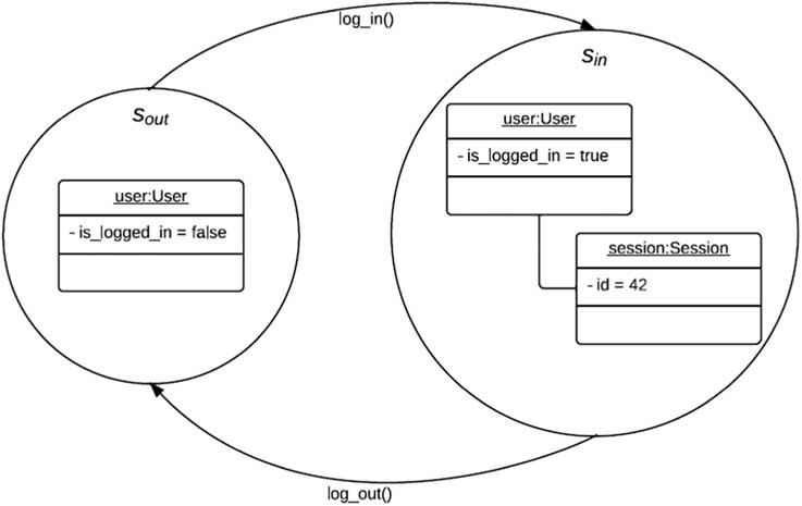
Figure 4 shows a simple example of the states and state transitions of the planning model described so far. As mentioned above, a state can be composed of a set of objects and links between them. The two states s out and s in represent the object models where the user is logged out and is logged in respectively. s out contains a single object, user, which is an instance of a User class that has one boolean attribute, is_logged_in, and two methods, log_in and log_out. s in contains two objects: user and session, which is an instance of a Session class and which gets instantiated for the user upon his login. Invocations of the methods log_in and log_out cause state transitions from one state to the other. This example highlights the fact that states can grow or shrink as objects are instantiated or terminated.
States (as object models) and state transitions

4.1.4 Problems, plans, and solutions
For the purpose of planning messages in sequence diagrams, a planning problem is defined as a triple P=(Σ; s 0; S g ), where:
∙ Σ is the state-transition system defined above.
∙ s 0 ∈ S is an initial state, which represents the object model specified by the use case pre-conditions.
∙ S g ⊆ S is a set of goal states. This set represents the object models that satisfy the use case post-conditions.
Just as Ghallab et al. (Reference Ghallab, Nau and Traverso2004) distinguish between a planning problem P and its statement P (to be able to specify P without enumerating all the states and state transitions), the statement of P is defined here as the triple P=(M; s 0; g), where g is a set of goal conditions: conditions that a state must satisfy for it to be a goal state. Using the use case post-conditions as the goal conditions, g specifies S g , which represents all the object models that satisfy the use case post-conditions. The use case post-conditions represent objects in certain internal states. The notion of ‘unsatisfied object’ refers to an object whose internal state does not satisfy the conditions on this object as specified in the use case’s post-conditions.
For reasons that will become clear in Section 4.2, a plan in the context of sequence diagram generation is not defined as it is usually defined in a general planning context: any sequence of actions. Instead, a plan π is defined as any sequence of messages (µ 1, … , µ k ), k≥ 0, where each message µ i consists of an action m i , a sender, and a receiver. The length of the plan is |π|=k.
To be able to denote the state s’ that results from applying a plan π to a state s, the state-transition function needs to be extended as follows:
 $$\gamma \left( {s,\pi } \right){\equals}\left\{ {\matrix{ s\hfill & {{\rm \hskip-14ptif}\,k{\equals}0} \cr {\gamma \left( {\gamma \left( {s,m_{1} } \right),\left\langle {\mu _{2} ,\hskip-2pt...,\mu _{k} } \right\rangle } \right)} & {{\rm \hskip-10ptif}\,k\,\gt\,0} \cr {{\rm undefined}}\hfill & {{\rm otherwise}} \cr } \,{\rm and}\,m_{{\rm 1}} \,{\rm is}\,{\rm applicable}\,{\rm in}\,s} \right.$$
To put it in other words, s’=γ(s, π) is the state that results from applying the methods of π one by one and in the order they are given in π. With this extended γ, a plan π is said to be a solution for a planning problem P having a statement P=(M, s 0, g) if γ(s 0, π) satisfies g. That is, if applying π to the initial state s 0 produces a goal state (a state that satisfies the set of goal conditions g).
4.2 Challenges in message planning
Based on the conceptual model presented at the beginning of Section 4.1, one might initially be tempted to think that solving a planning problem P in the context of sequence diagrams consists of finding a sequence of methods (m 1, m 2, … , m k ) the execution of which, starting from an initial object model s 0, will result in an object model that satisfies the given goal conditions (i.e. use case post-conditions). However, the sequence of methods (m 1, m 2, … , m k ) is not enough to actually generate a sequence diagram. The reason, in a nutshell, is that a sequence diagram depicts more than a sequence of method; it depicts a sequence of messages. To put it differently, a sequence of methods, just like a sequence of actions, is unidimensional, while a sequence diagram is two-dimensional.
In a sequence diagram, the vertical dimension shows how the messages are ordered in time. On the horizontal dimension, each message specifies, in addition to the method the execution of which is being requested, a sender and a receiver. So even though the sequence of methods (m 1, m 2, … , m k ) may represent the correct chronological order of the messages that need to be sent, it does not contain any information about the senders and receivers of those messages.
Assuming that each message maps to a certain method, determining the receiver of a message is relatively easy. The reason is that methods are not disembodied actions: methods do not exist on their own; they are defined in some class and are executed in some instance of that class. Furthermore, this type of information is static: it does not change from state to state. Since every method essentially always belongs to a specific object, once an automated planner decides that a certain method needs to be executed next, it can determine the object to which the method belongs using the class or object model and, in turn, determine the receiver of the message that needs to be sent.
The more challenging task is determining the sender of a message. The reason is that this type of information is dynamic: it may change from one state to the other. An object can send a message to a receiving object if it has a link to it; the object cannot send messages to other objects to which it is not linked. Because links are dynamic and can change over time, a valid sender of a message in some state may become an invalid sender in the next. Based on this, information about the senders of messages cannot be statically added to the problem description in advance. Instead, the automated planner must dynamically infer such information using the links between the objects in the current state. To recap, handling the message planning problem within the context of sequence diagram generation requires simulation of the changes in the object model from one state to another due to message passing. As powerful as they are, representations for action planning—such as STRIPS (Fikes & Nilsson, Reference Fikes and Nilsson1971), ADL (Pednault, Reference Pednault1989, Reference Pednault1994), and the PDDL (McDermott et al., Reference McDermott, Ghallab, Howe, Knoblock, Ram, Veloso, Weld and Wilkins1998)—do not readily contain constructs that support concepts and semantics of the UML and object-oriented software modeling directly.
Of course, some tricks can be used in action planning representations to simulate or support such concepts. For example, a pop() method of a Stack class that accesses a count attribute of Stack in its pre-conditions and post-conditions can be modeled in PDDL as a pop action that takes a stack as a parameter and uses a count function that itself takes a stack. However, such support for UML and object-oriented software modeling concepts is not as natural as it is in a representation that was designed with UML and object-orientation in mind, such as OCL. Therefore, a message planner that operates on UML models should ideally use OCL or a similar object-oriented representation instead of an action-planning representation.
4.3 The planning algorithm
The formalism of planning must provide a language and an algorithm. The language is meant to represent states, goals, and actions. The algorithm is meant for constructing a sequence of actions which transforms an initial state into a goal state. Various classes of algorithm have been employed; this includes but not limited to deductive algorithms based on theorem proving, state-based algorithms based on state space search, constraints satisfaction algorithms, and propositional satisfiablility algorithms. Additionally, more complex forms of planning algorithms are available, for example, in the framework of Marvov decision processes, to deal with uncertainty due to, for example, non-determinism and partial observability. Moreover, another class of algorithm is available to handle temporal planning where multiple actions can be taken simultaneously, their durations may vary, and actions and events may have interdependencies that dictate which combinations are possible. Interested readers are advised to consult Ghallab et al. (Reference Ghallab, Nau and Traverso2004) for details of the various classes of algorithms employed. Ghallab et al. (Reference Ghallab, Nau and Traverso2004) noted that the simplest classical planning algorithms are state-space search algorithms. These are search algorithms in which the search space is a subset of the state space. As a major objective of this research is to show that the core activity of sequence diagram generation can indeed be treated as a planning problem and solved as such, we opted to use a simple state-space search algorithm as a proof of concept. Future work will consider the analysis of the performance of more optimized algorithms.
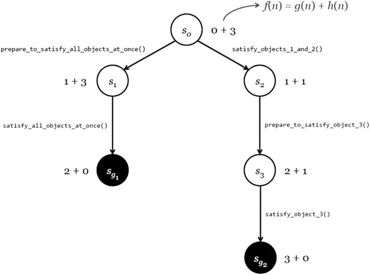
A forward-search algorithm for message planning is given in Algorithm 1. Algorithm 1 takes an initial state s 0, which represents an object model, and a set of goal conditions g. It uses a priority queue to save the generated states and selects the next state to be explored, which is the state that minimizes an objective function f(n). Because a priority queue is used, different control strategies (such as depth-first and breadth-first) can be used by changing f(n). It is worth noting that Algorithm 1 is an implementation of a generic A* search. We adapted A* to our planning problem by embedding some domain-specific notions such as the notion of applicability of a method. Ghallab et al. (Reference Ghallab, Nau and Traverso2004) pointed out that search with an A* algorithm is feasible as long as the refinement cost from one partial plan to the next is not null. This aspect and others related to f(n) are discussed further in Subsection 4.3.1.

When Algorithm 1 finds a state that satisfies g, it returns a solution π, which is the sequence of messages that leads to that state. If all states were explored and none of them were found to be a goal state, Algorithm 1 returns failure. Tracing the algorithm with an example is given in Experiment 3 (Section 6.3).
4.3.1 The objective function f(n)
The objective function f(n), where n is a node consisting of a state (object model) and the sequence of messages leading to it, facilitates having different control strategies for exploring the nodes in the search space. Depth-first, breadth-first, and best-first control strategies can be implemented by defining f(n) as follows:
 $$f\left( n \right){\equals}\left\{ {\matrix{ {{\minus}g\left( n \right){\rm }}\hfill & {{\rm for}\,{\rm depth\hbox{-}first}\,{\rm search}} \cr {g\left( n \right)}\hfill & {{\rm \hskip8ptfor}\,{\rm breadth\hbox{-}first}\,{\rm search}} \cr {g\left( n \right){\plus}h\left( n \right)} & {{\rm \hskip-6ptfor}\,{\rm best\hbox{-}first}\,{\rm search}} \cr } } \right.$$
The function g(n) is the cost to reach the node n, and is equal to the number of messages that lead to the object model represented by the state contained in n. Because the planning algorithm uses a priority queue to store states in an ascending order of f-values, the objective function f(n)=−g(n) gives deeper nodes higher priority. For the same reason, f(n)=g(n) gives shallower nodes higher priority.
The heuristic function h(n) is the estimated cost of the cheapest path from the node n to a goal node. In other words, it is the planner’s guess of the number of messages still needed to produce an object model that satisfies the goal conditions. h(n) and its properties will be discussed further in the next subsection.
4.3.2 The heuristic function h(n)
One way to specify the goal conditions is to use a collection of key-value pairs where each key is an object name and the value is the conditions that the object must satisfy. Using this specification, h(n) can be defined as follows:
 $$h\left( n \right){\equals}the\,number\,of\,objects\,not\,satisfying\,their\,conditions$$
That is, a planner using this h(n) will estimate the number of messages still needed to produce a goal object model from the current one is equal to the number of objects not satisfying their goals. So, for example, if there are two unsatisfied objects in the current object model, the planner will estimate that two more messages are needed to satisfy the two objects. The rationale here is that each object might need one message to satisfy its goal. Of course, this is only an estimate based on heuristic and thus it can be wrong. So it may be the case that one more message will actually satisfy the two objects together. So h(n) is not admissible: it may overestimate the true cost of reaching the goal (Russell & Norvig, Reference Russell and Norvig2009).
Since h(n) is not admissible, the planner’s best-first search is not optimal and may return a non-optimal solution. One of the experiments presented in Section 6 demonstrates the non-optimality of the planner’s best-first search with a simple contrived example.
4.3.3 Sender-selection rules
As was discussed in Section 4.2, a message planner must dynamically infer, based on the current state, the sender of each message in the current sequence of messages. Based on the sequence diagrams encountered during this research, a list of rules of thumbs for message planners to use when selecting a sender was compiled. After the planner determines the receiver of the message under consideration, the planner can use the rules listed below to select a sender for the message.
Rule of Thumb 1: If the message is the first in the sequence of messages, select the Actor as the sender.
Actors initiate use cases to access the functionality provided by a software system. So, in a sequence diagram that models the interactions between objects participating in a use case, the sender of the first message is the actor initiating that use case. It is worth noting here that this rule would be applicable in early stages of rigorous requirements engineering processes where only entity classes are identified.
Rule of Thumb 2: If the receiver of the message is a boundary object, select the Actor as the sender.
Boundary objects represent the interactions between the user and the system. Therefore, a message received by a boundary object is most likely sent by the actor. It is worth noting here too that although the focus here is on early stages of rigorous requirements engineering processes; where only entity classes are identified; this rule considers boundary classes in case they are available. The rule could be applicable to control classes as well; albeit control classes are not typically identified at early stages of rigorous requirements engineering processes.
Rule of Thumb 3: If the receiver of the message is a dependency object (i.e. an object that received a <<create>>message at a previous point in time), select the object’s creator (i.e. the object that sent it the <<create>>message) as the sender.
In sequence diagrams, objects may instantiate other objects by sending <<create>>messages. In such a case, the dependent object instantiates the independent object usually to use it by sending it further messages. So, a message received by the independent object is most probably sent by the dependent object that instantiated it in the first place.
Rule of Thumb 4: If the message has more than one candidate sender, where an object is considered as a candidate sender of a message if the object has a link to the receiver of that message and has been previously activated (i.e. it received a message at an earlier point in time), select the candidate sender that was activated most recently (i.e. the last candidate sender to receive a message) as the sender.
Based on the sequence diagrams encountered in this research, the candidate sender of a message most likely to be the correct one (that is, the one selected by the sequence diagram creator) is the most recently activated one.
Rule of Thumb 5: Using the definition of a candidate sender given in the previous rules, if the message does not have any candidate sender, select the Actor as the sender.
Since the planner has determined that the message must be sent to make the resulting sequence diagram a solution to the use case at hand, it must select a sender even if there are no candidate ones. If that is the case, there is always the possibility that the actor is the sender of that crucial message.
It is noteworthy that Section 7 presents a number of limitations still to be addressed. Future work may develop other rules to address such limitations.
As they are rules of thumb, the planner may select a sender other than the one that the software designer originally had in mind. That is, the output of the planner may result in a sequence diagram that is different—in terms of the senders of the messages—from the one that the software designer may have come up with manually. One of the experiments presented in Section 6 demonstrates an example where one of the rules listed above caused the planner to produce an output that is different from the original manually designed sequence diagram.
5 Implementation overview
Due to the challenges faced in adapting existing action planners to the domain of sequence diagram generation as discussed in Section 4.2, we implemented an automated planner that is specialized for planning messages in sequence diagrams: Communiqué. Communiqué, was implemented in Ruby 1.9.3, which is a dynamic object-oriented programming language (Thomas et al., Reference Thomas, Fowler and Hunt2012). Communiqué is developed to offer a proof of concept.
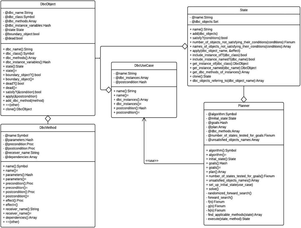
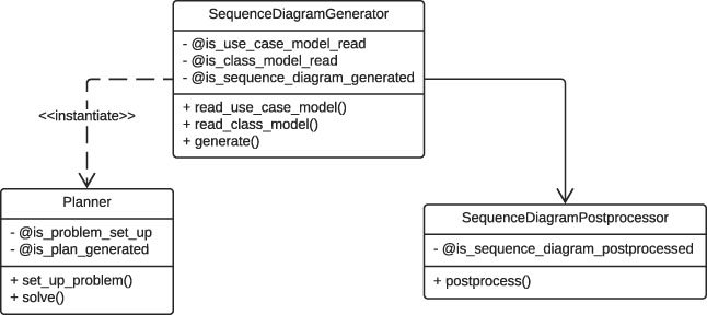
Figure 5 shows the class diagram of Communiqué. Since Ruby is a dynamically typed language, the types shown in the classes represent intended types. Following the syntax of Ruby, for instance, variables, attributes are preceded with the @ sign. The DbcMethod class represents a method with pre-conditions and post-conditions. The DbcObject class represents objects the methods of which have pre-conditions and post-conditions. The DbcUseCase class represents a use case that is designed following the DbC approach. The State class represents the states of the planning model. Those states are basically object models. The Planner class is the core class of Communiqué and uses DbcUseCases and States to plan sequences of message passes.
The class diagram of Communiqué

Let us use this simple illustrative example to demonstrate the usage of Communiqué. Assume that there is a User class that has a single boolean is_logged_in attribute and two methods, log_in and log_out, that set the boolean attribute to true and false, respectively. Assume further that log_in must not be called if the user is already logged in, and that log_out must not be called if the user is already logged out.
Instances of User can be created as follows:
user_instance=DbcObject.new(‘user’, :User , {
:@is_logged_in=>false
})
The above essentially creates an instance of User named user (that can have methods with pre-conditions and post-conditions) and sets the is_logged_in to the default value of false.
The log_in method with its pre-condition and post-condition can be specified in Communiqué as shown below:
log_in=DbcMethod.new(:log_in)
log_in.precondition=Proc.new { ! @is_logged_in }
log_in.postcondition=Proc.new { @is_logged_in=true }
The first line simply creates the method and gives it a name, the second specifies the method’s pre-condition, and the third specifies the post-condition. Before continuing with the example, the way in which pre-conditions and post-conditions are specified and handled in Communiqué is worth elaborating on here.
In Communiqué, pre-conditions and post-conditions are expected to be instances of Proc. Procs are code blocks, which are simply chunks of code enclosed between braces or the do and end keywords, that are converted to objects. These blocks-turned-objects can be, like any other object, stored in variables and passed around as parameters, but unlike non-block objects, they can be executed.
Communiqué uses pre-condition blocks to determine which of the methods are applicable to the current state. It does that by evaluating the pre-condition block in the context of the DbcObject instance to which the method belongs and observing whether the block evaluates to true or to false. In a similar manner, Communiqué uses post-condition blocks to compute the state-transition function γ(s, m), that is, the state that results from applying a method m to the current state s. In other words, a pre-condition or post-condition block in Communiqué is what Paolo Perrotta calls a ‘Context Probe, … a snippet of code that you dip inside an object to do something in there’ (Perrotta, Reference Perrotta2010). Therefore, the contract of a method should generally be written from the point of view of the object to which the method belongs.
By using Ruby code blocks, the need to implement a parser for some contract language was avoided. Instead, Communiqué uses Ruby itself, which is Turing complete, as the language for the contracts. This gives the user great power and flexibility because it means that the user can write almost whatever he or she wants in the contracts as long as it is valid Ruby code. For example, the user can specify the contracts in syntax similar to that of the OCL. For example, the OCL specification of the pop() method that was presented under Section 2.2 can be written in Communiqué as follows:
pop.precondition=Proc.new { not self.isfiempty? }
pop.postcondition=Proc.new { @count -= 1 }
Furthermore, Ruby collection classes (such as Array, Hash, and Set) with the methods they provide can be used to simulate OCL collections and their operations.
For example, assume that the pre-condition of a registerCourse method of a Student class is that the list of courses the student already registered does not contain the new course. This can be expressed in OCL as follows:
context Student::registerCourse(c:Course)
pre: not courses ->includes(c)
In Communiqué, the pre-condition above can be written as follows:
registerCourse.precondition=Proc.new do
not self.courses.include?(registerCourse.parameters[:c])
end
There is a caveat though. While the pre-condition block of a method in Communiqué is expected to be, just like in other contract languages, an expression that evaluates to true or false, the post-condition of the method is expected to be an expression (or a set of expressions) that actually changes something in the state, typically by assigning values to instance variables. If the block does not actually change something in the state, s 0=γ(s;m)=s. That is to say, although Communiqué will execute the post-condition block of an applicable method, if the block does not actually change something in the state, it will not contribute to solving the planning problem at hand.
Continuing with the example, the log_out method with its pre-condition and post-condition can be specified in Communiqué as shown below. This method is, in a sense, the inverse of the log_in method.
log_out=DbcMethod.new(:log_out)
log_out.precondition=Proc.new { @is_logged_in }
log_out.postcondition=Proc.new { @is_logged_in=false }
After specifying the methods with their pre-conditions and post-conditions, the methods should be added to the User instance as follows:
user_instance.add_dbc_methods(log_in, log_out)
Assume now that the use case that is to be realized with a sequence diagram is about a user who is initially logged out and wants to log in. The use case can be set up as follows:
login_use_case=DbcUseCase.new(‘Login’)
login_use_case.dbc_instances << user_instance
login_use_case.postconditions={
‘user’=>Proc.new { @is_logged_in }
}
The above creates a use case and gives it a name, adds the logged out User to it, and specifies that the User should be logged in at the end of the use case. In Communiqué, use case post-conditions are specified as a Ruby Hash, which is a set of key-value pairs, where the key is an instance name and the value is a code block representing the conditions on that instance.
Using the above models, the planning problem can be set up for a planner and then the planner can be requested to solve the problem as follows:
planner=Planner.new
planner.set_up_initial_state(login_use_case)
planner.goals=use_case.postconditions
planner.solve
If the planner finds a solution, it returns an Array of Hash, where each Hash represents a message passing specifying the message’s sender, its name, its parameters (if any), and its receiver.
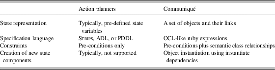
The implementation overview shows that, unlike action planners which are domain-independent, Communiqué is specific to message passing. Table 2 compares Communiqué as a message planner to existing action planners. Using Communiqué, we empirically showed that even with a simple conceptual model of restricted state-transition systems, determining the sequence of messages in sequence diagrams can be solved using forward state-search space.
Action planners vs. Communiqué as a message planner

STRIPS=Stanford Research Institute Problem Solver; ADL=Action Description Language; PDDD=Planning Domain Definition Language; OCL=Object Constraint Language.
The source code of Communiqué, along with the scripts for the experiments used in Section 6, is available onlineFootnote 1 .
6 Experiments and results
A number of different experiments were carried out to validate the proposed approach of using AI planning to plan messages in sequence diagrams, and to assess corresponding capabilities and limitations. Each of the following sections provides details about the purpose of the experiment, its set up, and its results. The full source code of the experiments scripts is available online along with the source code of Communiqué2. With regard to the design of our validation experiments, it is noteworthy that the UML models (especially the class diagrams) that were used in the experiments were not originally designed following the DbC concepts. That is, the operations of the classes did not have contracts (i.e. pre-conditions and post-conditions). Accordingly, we had to add the contracts to the models as if we were designing the models using DbC. Sometimes, adding a contract to a method of a class entailed adding a new attribute to that class. Most of the time, these added attributes were high-level boolean flags, such as an is_refreshed boolean attribute of a WatchDisplay class. Also, note that Communiqué does not currently generate actual diagrams: it generates text outputs that represent the sequence of messages of the solution sequence diagrams. The text output includes the necessary information for constructing a sequence diagram: the message’s sender, its name, its parameters (if any), and its receiver for each message. For conciseness and clarity, the command-line outputs will not be shown here. Instead, the sequence diagrams that correspond to those outputs will be shown directly. It is worth noting that we do not show the use case diagram corresponding to each experiment since we mainly use descriptions of the use cases in terms of their pre-conditions and post-conditions as explained in Section 2.1.
6.1 Experiment 1: examples from the literature
We conducted some initial experiments with simple sequence diagrams of senior projects of undergraduate students: each sequence diagram involved one object and at most two messages. Communiqué was able to reconstruct all sequence diagrams (Sulaiman, Reference Sulaiman2013). We report in this experiment the output of Communiqué when trying to generate more complex sequence diagrams. As target sequence diagrams for this experiment, three sequence diagrams were selected from three different systems: the 2Bwatch system and the ARENA system (Bruegge & Dutoit, Reference Bruegge and Dutoit2010), and the Weather Station System (Sommerville, Reference Sommerville2004).
6.1.1 2Bwatch system
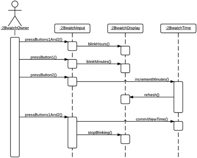
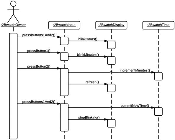
The first sequence diagram picked as a target for this experiment is the one for the 2Bwatch system (also referred to as SimpleWatch) by Bruegge and Dutoit (Reference Bruegge and Dutoit2010). 2Bwatch represents a 2-button watch, the user of which may either consult the time on the watch (with the ReadTime use case) or set it (with the SetTime use case). The use case diagram is shown in Figure 1. The sequence diagram in question, which is reproduced in Figure 6 for the reader’s reference, is for an actor setting the watch 1 minute ahead.
Setting the time on a 2-button watch 1 minute ahead (Bruegge & Dutoit, Reference Bruegge and Dutoit2010)

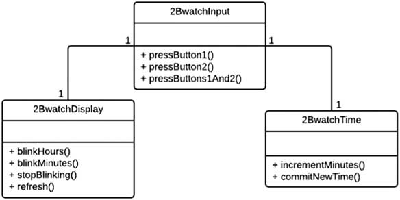
Ruby code was developed to set up the inputs for the 2Bwatch experiment (Sulaiman, Reference Sulaiman2013). The code creates an instance of the class diagram depicted in Figure 7. This instance is used as the initial object model for the use case. The use case set up is as follows:
The class diagram of 2Bwatch

set_time_use_case=DbcUseCase.new(‘Set Time’)
set_time_use_case.dbc_instances << display << time << watch
set_time_use_case.postconditions={
‘display’=>Proc.new { @blinking== :none },
‘time’=>Proc.new { @is_new_time_committed },
‘watch’=>Proc.new { @mode== :read_time }
}
The code also creates the methods and the other contracts that are used in this experiment.
Figure 8 shows the sequence diagram corresponding to the output of Communiqué for this experiment. This generated sequence diagram is slightly different from the original manually designed one. In the original sequence diagram, a refresh message is sent from the 2BwatchTime instance. In the generated sequence diagram, the refresh message is sent from the 2BwatchInput instance. Using Yue et al.’s (Reference Yue, Briand and Labiche2013) measurements, the completeness, correctness, and redundancy of the sequence diagram of Figure 8 are 90, 90, and 0%, respectively.
Communiqué’s initial output

Further inspection of this difference revealed that there is an inconsistency in the original manually designed models. The inconsistency is that there is no association in the class diagram (Figure 7) between 2BwatchTime and 2BwatchDisplay to allow instances of the former to send messages to instances of the latter as is the case in the sequence diagram (Figure 6). It may be the case that Bruegge and Dutoit (Reference Bruegge and Dutoit2010) did not show that particular association because they were concentrating in their figure 2–2 on the main class, 2BwatchInput, and its associations only. Regardless, the fact is that there is only one class diagram related to the system under consideration, and from the sequence diagram’s viewpoint, it is missing a necessary association. As there was no association from the 2BwatchTime instance to the 2BwatchDisplay instance, the planner of Communiqué did not consider the 2BwatchTime as a valid sender of the refresh message and selected the 2BwatchInput instance instead.
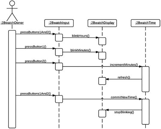
Figure 9 shows the sequence diagram corresponding to Communiqué’s output after adding the missing association by linking the 2BwatchTime instance to the 2BwatchDisplay instance. This time, the planner selected the 2BwatchTime as the sender of the refresh message, matching the textbook’s sequence diagram, but it changed the sender of the stopBlinking message: instead of the 2BwatchInput instance, the planner selected the 2BwatchTime instance. The reason behind this change is that after adding the missing association, the stopBlinking message now had two candidate senders. Using the Rule of Thumb 4 mentioned in Subsection 4.3.3, the planner selected the candidate sender that was activated most recently, namely, the 2BwatchTime instance. The completeness, correctness, and redundancy of the sequence diagram of Figure 9 are also 90, 90 and 0%, respectively.
Communiqué’s output after adding the missing association

6.1.2 ARENA system
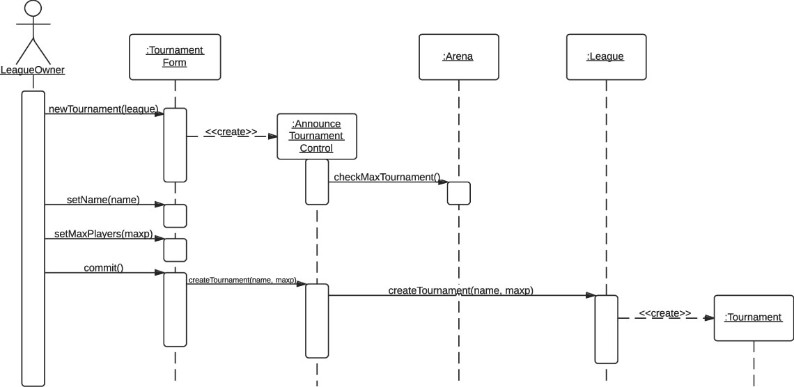
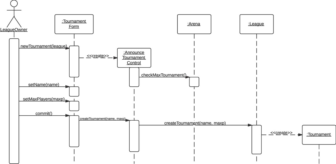
The second sequence diagram picked as a target for this experiment is the one for the ARENA system, a web-based system for organizing and conducting tournaments by Bruegge and Dutoit (Reference Bruegge and Dutoit2010). The sequence diagram in question, which is reproduced in Figure 10 for the reader’s reference, is for a tournament creation workflow of a tournament announcement use case.
Tournament creation workflow of the Announce Tournament use case of ARENA (Bruegge & Dutoit, Reference Bruegge and Dutoit2010: 247)

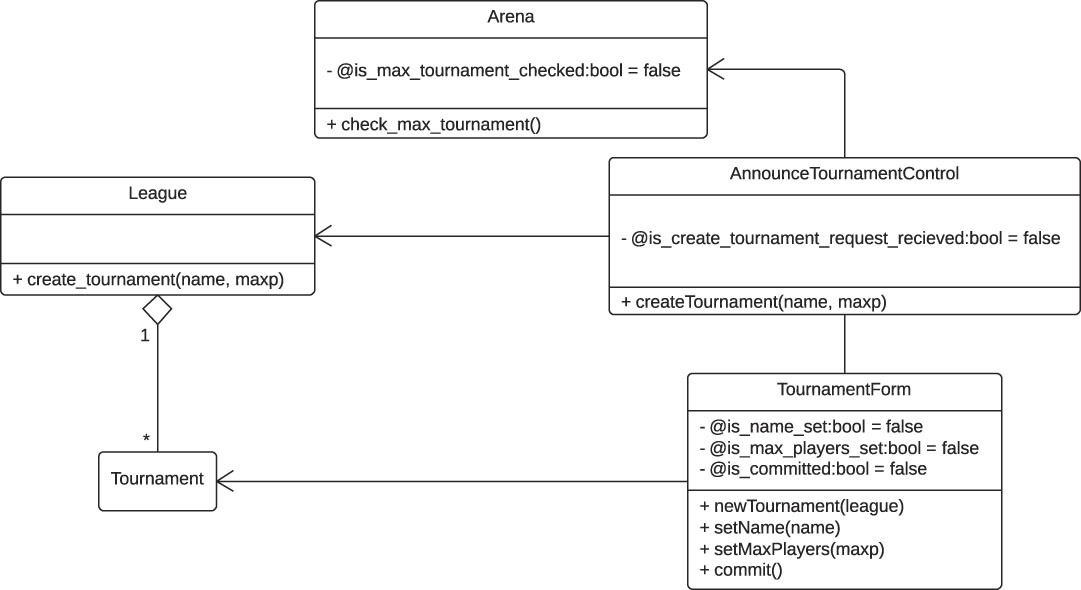
Ruby code was developed to set up the inputs for the ARENA system experiment (Sulaiman, Reference Sulaiman2013). The code creates an instance of the class diagram depicted in Figure 11. This instance is used as the initial object model for the use case. The use case set up is as follows:
The class diagram of ARENA

announce_tournament_use_case=DbcUseCase.new(‘AnnounceTournament’)
announce_tournament_use_case.dbc_instances << tournament_form
<< announce_tournament_control << arena << league << tournament
announce_tournament_use_case.postconditions={
'tournament’=>Proc.new { ! dead? }
}
The code also creates all other relevant elements.
Figure 12 shows the sequence diagram corresponding to the output of Communiqué for this experiment. This sequence diagram matches the original one that was designed manually (Figure 10). The completeness, correctness, and redundancy of the generated sequence diagram are 100, 100 and 0%, respectively.
Communiqué’s output for the tournament creation workflow

6.1.3 Weather station system
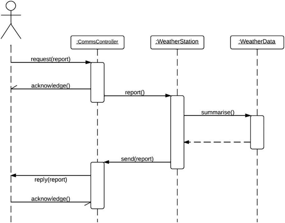
The third sequence diagram picked as a target for this experiment is the one for the Weather Station System depicted by Sommerville (Sommerville, Reference Sommerville2004). The sequence diagram in question, which is reproduced in Figure 13 for the reader’s reference, is for a data collection use case in which an external mapping system requests data from the weather station.
Collecting data from a weather station (Sommerville, Reference Sommerville2004)

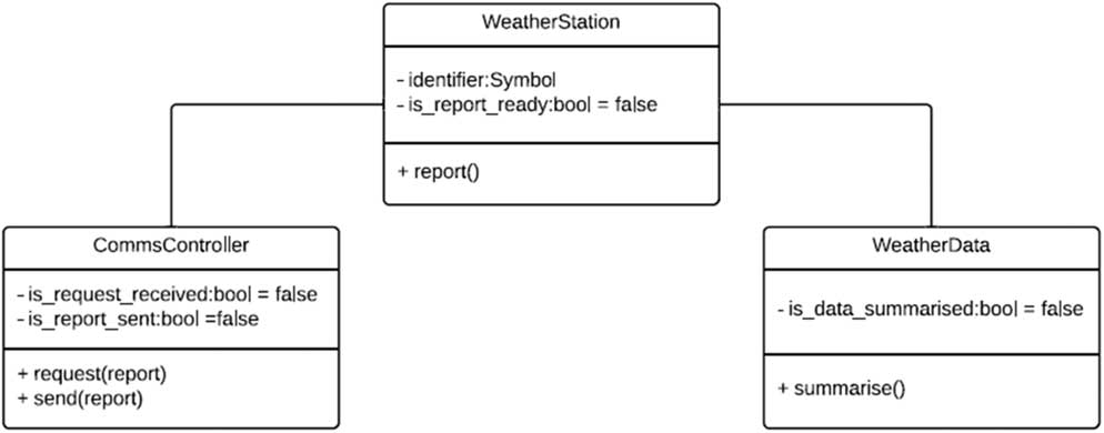
Ruby code was developed to set up the inputs for the weather station system experiment (Sulaiman, Reference Sulaiman2013). The code creates an instance of the class diagram depicted in Figure 14. This instance is used as the initial object model for the use case. The use case is set up as follows:
The class diagram of the weather station system

collect_data_use_case=DbcUseCase.new(‘Collect Data’)
collect_data_use_case.dbc_instances << comms_controller << weather_station << weather_data
collect_data_use_case.postconditions={
‘comms_controller’=>Proc.new { @is_report_sent }
}
The code also creates all other relevant elements.
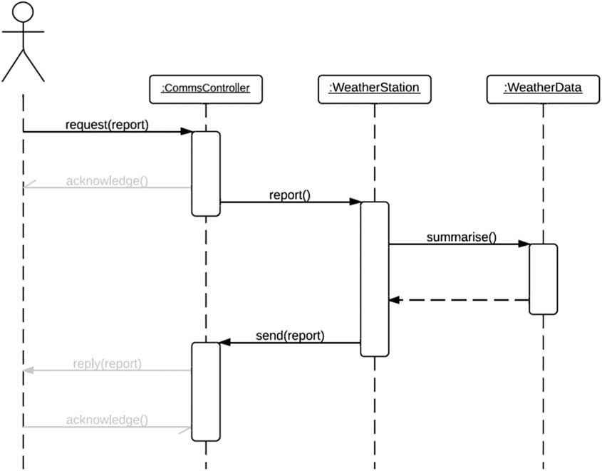
Figure 15 shows the sequence diagram corresponding to the output of Communiqué. The three greyed out messages in the diagram represent the messages that Communiqué did not generate, mainly because it currently does not support sending messages back to the actor. Other than those three messages, the generated sequence diagram matches the one that was designed manually. The completeness, correctness, and redundancy of the generated sequence diagram are 58, 100 and 0%, respectively. It is worth noting that the completeness is still better that than 50% completeness of the 4th-year undergraduate students in Yue et al.’s (Reference Yue, Briand and Labiche2013) experiment.
Communiqué’s output for the data collection use case of the weather station system

6.2 Experiment 2: effects of large classes
The class diagrams that were used in the previous experiments had a particular feature in common: they were small. A class diagram of a real-world software system will almost certainly be larger and contain more classes and methods. For a particular use case, many—if not most—of those methods will be irrelevant. This experiment was designed to see how classes with large number of methods would affect the performance of Communiqué’s planner. The intent here is to work with large number of operations. Having a large number of classes is irrelevant in this case since the initial state of the corresponding use case’s pre-conditions and the subsequent states would not be impacted. Each state would have an object model with only those objects relevant to the sequence diagram. Those objects are to have large number of operations so that the search space is large.
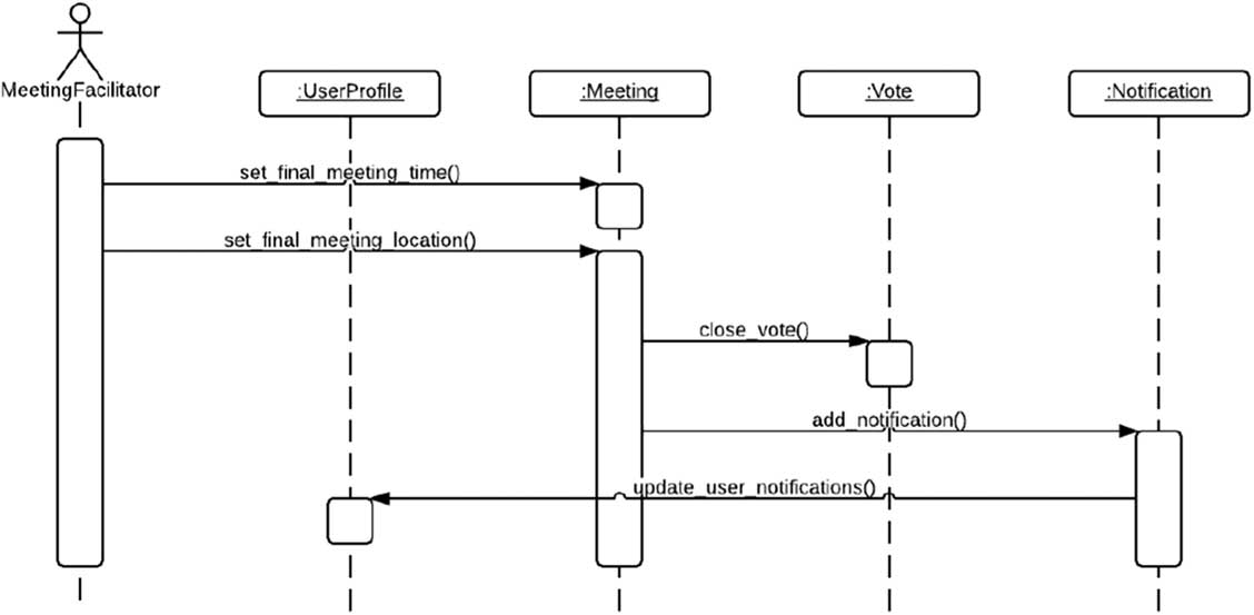
The UML models used in this experiment are based upon the MeetingsMate system by Al Akel et al. (Reference Al Akel, Al Kalaji, Labani, Al Hazemi, Ba Haziq and Al Zahrani2011). The system provides a solution for scheduling and managing work meetings. For this experiment, we selected the Finalize Meeting use case of the MeetingsMate system. Figure 16 shows the manually designed sequence diagram that realized that use case.
Finalize Meeting use case of the MeetingsMate system (Al Akel et al., Reference Al Akel, Al Kalaji, Labani, Al Hazemi, Ba Haziq and Al Zahrani2011)

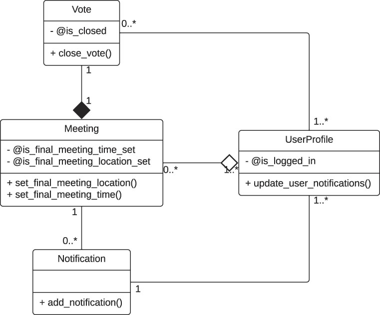
Ruby code was developed to set up the inputs for this experiment (Sulaiman, Reference Sulaiman2013). The code creates an instance of the class diagram depicted in Figure 17, which is the part of the system’s class diagram that is relevant to the selected use case. This instance is used as the initial object model for the use case. The code also creates all relevant elements and sets up the use case’s post-conditions.
Class diagram of Experiment 2

To avoid having to redesign a large class diagram using DbC, we automatically generated noise methods. A noise method is a method that is always applicable (i.e. its pre-condition is true) and that does not change the state at all (i.e. its post-condition is empty). In other words, noise methods are irrelevant methods that do not contribute towards satisfying the post-conditions of the use case at hand. By adding noise methods in a dummy object to the relevant methods that already exist in the original model, a large class diagram can be, to some extent, simulated.
For this particular experiment, the number of noise methods, m, were varied from 0 to 10. To study the effects of noise methods on the performance of the three search algorithm (depth-first, breadth-first, and best-first), the experiment script effectively created 30 search spaces for each number of noise methods m=0, 1, 2,…, 10. This was achieved by shuffling the current set of methods collected by the planner just before it began to solve the problem at hand. To generate the same sequence of search spaces for the different search algorithms and to make the results reproducible, the pseudo-random number generator that was used for the shuffling was initialized with a fixed seed.
Three quantities were used to measure the performance of Communiqué’s planner relative to the number of noise methods:
1. The number of explored nodes, or more precisely, the number of states that the planner checked to see if they satisfy the use case post-conditions (number of goal tests for short).
2. The execution (real) time (as reported by the Benchmark module of Ruby) taken by the planner to solve the problem.
3. The length of the generated plan (that is, the number of messages of the generated sequence diagram).
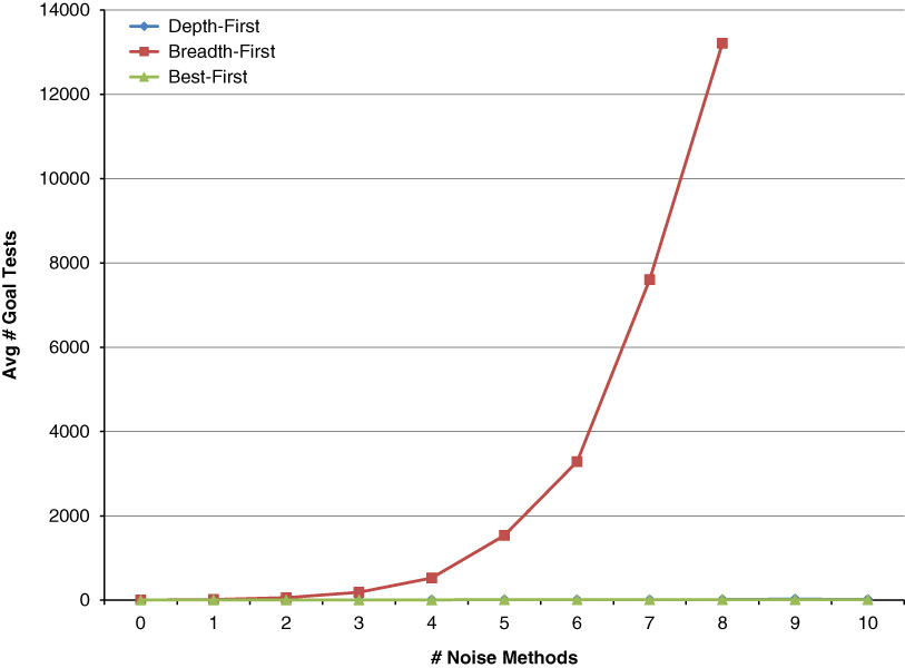
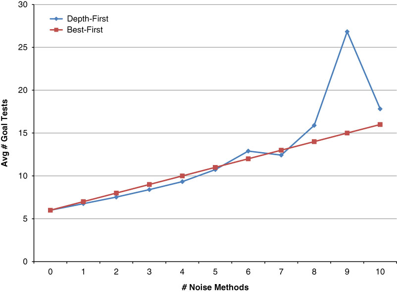
Figure 18 shows the effects of noise methods on the number of goal tests. As the number of noise methods m increased, the average number of states breadth-first explored grew exponentially. The figure does not distinguish between the performance of depth-first and the performance of best-first due to scaling. Figure 19 compares the performance of depth-first and best-first more clearly. Depth-first and best-first explored, on average, a similar number of states and did not exhibit the exponential growth of breadth-first.
The effect of noise methods on the number of goal tests

The effect of noise methods on the number of goal tests for depth and best-first

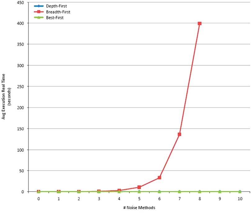
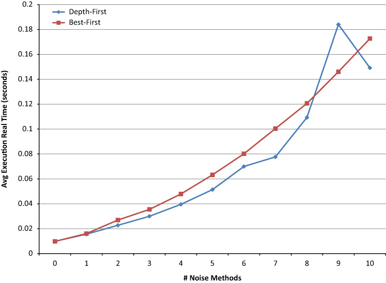
Figure 20 shows the effect of noise methods on the execution real time of the three search algorithms. Since this time is directly influenced by the number of explored states, the average time breadth-first took to find the optimal solution grew exponentially as the number of noise methods m increased. Depth- and best-first are compared more clearly in Figure 21. Depth-first generally took less time than best-first to find a solution. The extra time best-first took to find the optimal solution was mainly spent in calculating the heuristic function h(n) discussed in Subsection 4.3.2.
The effect of noise methods on the execution real time

The effect of noise methods on the execution real time of depth- and best-first

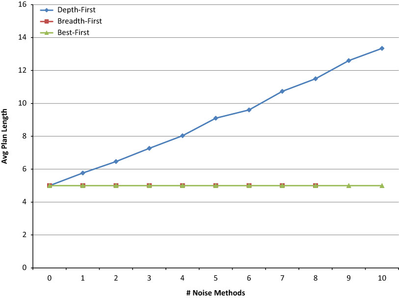
Figure 22 shows the effect of noise methods on the length of the generated plan. While breadth-first and best-first always returned the optimal plan (of length 5), the average length of the plan returned by depth-first grew linearly with the number of noise methods m. That is, the output of Communiqué when using breadth-first and best-first always matched the manually designed sequence diagram shown in Figure 16. On the other hand, the outputs obtained using depth-first contained extra noise-method invocations scattered throughout the sequence diagram, and the number of these invocations increased with the increase of noise methods.
The effect of noise methods on the plan length

To summarize, depth-first generally explored fewer states and spent less time than both breadth-first and best-first to find a solution, but the length of that solution increased linearly with the number of noise methods. Breadth-first was able to always find the optimal solution, but the number of states it had to explore (and, as a consequence, the time it had to spend) to find that optimal solution grew exponentially with the number of noise methods. Best-first was able to strike a balance by always finding the optimal solution while exploring a number of states (and spending an amount of time) that is close to that of depth-first and that increased linearly with the number of noise methods.
6.3 Experiment 3: non-optimality of best-first search
The purpose of this experiment is to demonstrate the non-optimality of Communiqué’s best-first search. As Subsection 4.3.2 explained, because the heuristic function h(n) that best-first search uses is not admissible, it may cause the planner to return a non-optimal solution.
For demonstration purposes, this experiment uses a simple contrived example. Ruby code was developed to set up the inputs for this experiment (Sulaiman, Reference Sulaiman2013). The code creates the instances, the methods, and the contracts that are used in this experiment. The code also sets up the post-conditions of the use case so that the goal becomes getting the controller to satisfy the three objects it contains (i.e. setting the is_satisfied boolean attribute to true for each of the three objects). Figure 23 shows the class diagram of which an instance is created by the code. The pre-conditions and post-conditions of the methods are deliberately set up so that there are two solutions: one consists of two messages (Figure 24), while the other consists of three (Figure 25).
The class diagram used for Experiment 3

The optimal sequence diagram for Experiment 3

The non-optimal sequence diagram for Experiment 3

Figure 24 shows the sequence diagram corresponding to the optimal solution, which is returned by depth-first and breadth-first search, while Figure 25 shows the sequence diagram corresponding to the non-optimal solution, which is the one best-first search returns.
Figure 26 shows the search space that Communiqué explores in this experiment. Each node represents a state in the search space, where the dark nodes represent goal states. The numbers in front of each state are the values that constitute the objective function f(n)=g(n)+h(n) for that state, where g(n) is the cost (in terms of the number of method calls) of reaching the state, and the heuristic function h(n) is the estimated cost of reaching the nearest goal from the state. In the first iteration, Communiqué generates the states s 1 and s 2 and enqueues them with the f-values 4 and 2, respectively. In the second iteration, it dequeues s 2 (because it has the lowest f-value), generates its child s 3, and enqueues it with an f-value of 3. In the next iteration, it dequeues s 3 (again, because it has the lowest f-value), generates its child sg 2, and enqueues it with an f-value of 3. In the final iteration, it dequeues sg 2 and finds that it is a goal state, so it returns the (non-optimal) solution corresponding to the path s 0; s 2; s 3; sg 2.
The search space for Experiment 4

Using depth-first as the control strategy leads Communiqué down the other, shorter path (s 0; s 1; sg 1) and results in finding the optimal solution. Note that in this particular experiment depth-first search found the optimal solution because the methods happened to be added to the initial object model in an order that leads the search down the shortest path first. Because depth-first is sensitive to the order in which the methods are added, reversing the order in which the methods that lead to the children of s 0 are added will cause depth-first search to go down the other, longer path and, as a result, return the non-optimal solution.
Using breadth-first as the control strategy also results in finding the optimal solution as forward-search explores s 0, s 1, s 2, and finally sg 1.
6.4 Experiment 4: object instantiation
The purpose of this experiment is to demonstrate the support of Communiqué for object instantiation. In UML, a dependency is a relationship that basically indicates that a class depends on another: the dependent class (the client) uses the independent class (the supplier) in some way, such as a parameter or local variable of one of the dependent class’s methods. A dependency is depicted in a class diagram as a dashed arrow from the client to the supplier. An instantiation dependency (indicated graphically by labeling the arrow with <<instantiate>>) means that an operation of the client may create instances of the supplier.
Since instantiation dependencies do not specify which operation of the client creates instances of the supplier, software designers usually consult the sequence diagram involving the client and the supplier to get that information. Communiqué will not have such a sequence diagram to begin with. Therefore, Communiqué requires the user to specify the objects that a method can create, if any, in the initial object model.
For demonstration purposes, this experiment uses a simple contrived (meta-) example. Ruby code was developed to set up the inputs for this experiment (Sulaiman, Reference Sulaiman2013). The code creates an instance of the class diagram depicted in Figure 27. This instance is used as the initial object model for the use case. Note that in this artificial example, the generate method of the SequenceDiagramGenerator class creates instances of the Planner class. The code also creates all relevant elements and sets up the use case’s post-conditions.
The class diagram used for Experiment 4

Figure 28 shows the sequence diagram that corresponds to the solution returned by Communiqué. Communiqué sees that generate() depends on Planner but there is no Planner instance in the current state when generate() is called. So, it decides that a <<create>>message must be sent from the SequenceDiagramGenerator instance (the dependent object) to Planner (the independent object).
Communiqué’s output for Experiment 4

6.5 Experiment 5: failure handling
The purpose of this experiment is to show that Communiqué is capable of pointing out possible sources of inconsistencies that caused it to fail in finding a sequence diagram that satisfies the given use case post-conditions. It is noteworthy that the best-first search algorithm, which is being used by Communiqué's, is complete (Russell & Norvig, Reference Russell and Norvig2009). Being complete means that the algorithm is guaranteed to find a solution when there is one (Russell & Norvig, Reference Russell and Norvig2009). There is a number of reasons that can cause Communiqué to report that there is no solution, for example, there could be a mistake in a method’s pre-conditions or post-conditions, there could be a mistake in the use case’s pre-conditions or post-conditions, or a method that is necessary for satisfying the use case’s post-conditions could be missing altogether.
In case Communiqué fails to find a solution, by keeping track of the best state it has seen so far during its search for a solution, Communiqué can point out possible sources of inconsistency. In such a case, the planner uses that state to report the names of the objects it was not able to satisfy. Using this information, the software developer can go back and check the classes of those objects, their methods, and their contracts for mistakes or omissions.
For demonstration purposes, this experiment also uses a simple contrived (meta-) example. Ruby code was developed to set up the inputs for this experiment (Sulaiman, Reference Sulaiman2013). The code creates all relevant elements and creates an instance of the class diagram depicted in Figure 29. This instance is used as the initial object model for the use case. Notice that an inconsistency is intentionally introduced by not adding a save_diagram method to the SequenceDiagramGenerator class. This method is necessary for achieving one of the use case’s post-conditions.
The class diagram used for Experiment 5

Upon failure, Communiqué uses the best state it has seen so far during its search to report the names of the objects that remained unsatisfied. That is, any object whose internal state does not satisfy the conditions on this object as specified in the use case’s post-conditions. In this particular experiment, the unsatisfied object is sequence_diagram_generator.
This experiment shows an example of inconsistent use case with the given class diagram. It is worth discussing this relevant topic here. According to the representation framework analysis version of the view-points requirements analysis technique, models from different views are meant to be developed independently and then compared to discover requirements that would be missed using a single view (Rumbaugh et al., 1991; Sommerville, Reference Sommerville2004). The rationale behind this technique is that the independent development of the different views can lead to inconsistencies between the different models. Detecting and clearing such inconsistencies lead to the discovery of more requirements; this is actually an objective of this approach. Detecting inconsistencies can be done by cross-checking the different models of different views against each other and looking for system’s aspects that were captured in some views but not in others. For instance, every use case should be shown to be realizable by the classes and methods provided in the conceptual class model of the target system; that is the objects of the system can pass messages among themselves to allow offering the intended services. This can be shown using sequence diagrams. The sequence diagrams themselves should not contain classes and methods that do not exist in the class diagram. If some classes or methods remain unused even after realizing all use cases, then either they are redundant or there are missing use cases that were partially captured by the class diagram. The models are refined accordingly to remove such inconsistencies. Clearly, such refinements include discovering more use cases, classes, etc.
7 Threats to validity and limitations
Data scarcity poses a major threat to the validity of the results of this study; data scarcity is a common problem for software engineering research though. It has been very difficult to find real-world sets of use cases, class diagrams, and sequence diagrams for us to use for validation. Let alone that those sets should be enforcing DbC concepts. Moreover, there is no similar work or a benchmark with which to compare the performance of Communiqué against. Thus, we used textbook and projects of senior undergraduate students in our validation experiments. As was pointed out, the UML models used in the experiments were not originally designed following the DbC concepts. Accordingly, we had to add the contracts to the models ourselves as if we were designing the models using DbC. Of course, if the original software designers were to use DbC, they may have specified contracts different from ours. So, although we tried our best not to tailor the contracts to suite Communiqué, we acknowledge that we may have unintentionally introduced some kind of bias in the contracts and, consequently, the experiments. This may have not challenged Communiqué adequately as real-world problems would. We intend to target more empirical validations against industrial data in the future.
While what follows below are limitations, they are also part of the contribution of our research since the research avenue was new and largely unexplored. An objective of the research effort was to draw the attention of other researchers in the field to this new area; to shed a light on what else needs to be done to advance the application of AI planning to automatic sequence diagram generation.
A challenging limitation is related to the conceptual model of restricted state-transition systems (which was discussed in Section 4.1). That model takes the differences between action planning and message planning (which were discussed in Section 4.2) into account; it is adequate for determining the sequence of messages in a sequence diagram. On its own, however, that model is not adequate for determining the method activations of the sequence diagram. The reason is that ‘time is abstracted away in the state transition model’ (Ghallab et al., Reference Ghallab, Nau and Traverso2004). That is to say, the state transitions are instantaneous. What this means in practice is that, as Figure 30 demonstrates, Communiqué may apply the post-conditions of a method earlier than it ideally should. Communiqué applies the post-conditions of m 1 when the message is sent at time t 1 instead of at the end of m 1’s activation at time t 2. This may cause passing a message pre-maturely. For instance, consider calling m 2 by m 1. In this case, m 2 may require some of m 1’s post-conditions as part of m 2’s pre-conditions; and actually that specific m 1’s post conditions will not be true until after m 3’s execution, for example. However, such a situation is not that popular. Hence, it does not significantly impact the effectiveness of Communiqué. Nevertheless, the situation raises an interesting problem for investigation. In some cases, the problem could be fundamentally caused by methods that are not modular: the methods may be trying to achieve too much by asserting too many post-conditions. In such cases the solution would be to break down the method into smaller, more focused ones. However, this would not still solve the issue when the planner does not indeed handle time properly. Another solution would be to make the method calls at the end of the methods. Our future research will seek sound solutions to this problem.
The effects of instantaneous state transitions on message planning

As was discussed in Section 4.2, a challenging task in automatic sequence diagram generation is determining the sender of the message because links between the objects in a state are dynamic: they may change from one state to the other. So, a valid sender of a message in some state may become an invalid sender in the next. Because of this, information about the senders of messages cannot be statically added to the problem description in advance. Instead, the automated planner must dynamically infer such information using the links between the objects in the current state. Following the rules of thumb discussed in Subsection 4.3.3, Communiqué may select a sender other than the one that the software designer originally had in mind. That is, the output of the planner may result in a sequence diagram that is different—in terms of the senders of the messages—from the one that the software designer may have come up with manually. This was demonstrated with the experiment presented in Section 6.1.1. That experiment showed that Communiqué’s decision was sounder than the original sequence diagram due to the missing association. However, this might not be the case in other situations. More investigations and, consequently, possible refinements to the rules of thumb will be the subject of future work.
Another limitation is due to the fact that the heuristic function h(n) that Communiqué uses is not admissible; this makes Communiqué’s best-first search not optimal. The design of an admissible h(n) will be considered in our future research.
Communiqué does not currently support combined fragments, which are basically logical groupings of sets of messages in sequence diagrams. These fragments include alternatives (alt), loops (loop), and options (opt).
Communiqué can handle multiple actors of a use case as long as they do the same activities, which is the popular case in use cases involving multiple actors. In this case, all actors are simply treated the same and included in the sequences diagram in the same way. Current version of Communiqué cannot handle multiple actors doing different complementing activities within one use case; that is where there are more than one actor sends messages among themselves through the use case. This is considered to be a limitation in current version of Communiqué. It is worth noting here though that use cases that represent complementing actor activities are rare in reality since many of such use cases could be decomposed into multiple related use cases; each actor has a use case to accomplish its own particular goal.
8 Conclusion and future work
In this paper we showed that the core activity of sequence diagram generation (that is, determining the sequence of messages) can indeed be treated as a planning problem and solved as such. Along the way, we discovered challenges in adopting current action planners to sequence diagrams generation. Accordingly, we developed Communiqué, a software tool for planning messages in sequence diagrams.
Our future work will try to address the limitations discussed in Section 7. It is noteworthy here too that forward state-space search is only one of the many different AI planning algorithms. Another algorithm that uses the same planning model of state transition systems is backward state-space search. Moreover, other than searching a space of states, plan-space planning searches a space of plans. Future work will investigate how other planning approaches and algorithms can be applied to the problem of planning a sequence messages. Future work will also consider the analysis of the performance of more optimized algorithms than A*.
The reliance on Ruby, however, may prevent software designers/developers who do not know Ruby from using Communiqué. We ultimately plan to implement the proposed technique as a plug-in to a CASE tool. We plan the integration through the use of the XML Metadata Interchange (XMI) (Object Management Group, 2005), which is a standard for sharing metadata and models—especially UML models—using XML, as the format of the initial inputs and final outputs of the message planner. In this case, software designers/developers will just need to specify contracts in OCL with the CASE tool.
In our future work, we plan on applying our approach to the detection of consistency of use cases against class diagrams. Experiment 5 of Section 6 shows an example of inconsistent use case with the given class diagram.
Acknowledgments
The authors would like to acknowledge the support provided by the Deanship of Scientific Research at King Fahd University of Petroleum and Minerals (KFUPM) under Research Grant IN111013. Many thanks are due to the anonymous referees for their detailed and helpful comments.