NOMENCLATURE
Abbreviations
-
 $\textbf{\textit{A}}$
matrix relating laminate in-plane loads with strains
- A
loads matrix
-
$D$
vector from Origin
$O$
to intersection point
$T$
with the plane of a triangle- DOF
degrees of freedom
-
$E$
Young’s modulus
-
$f()$
function of
-
$G$
Shear modulus
- GFEM
Global Finite Element Model
- k-d tree
a space-partitioning data structure for organising points in k-dimensional space
- L
load
-
$L$
characteristic loads matrix
-
$m,n$
direction cosines
-
${N_x},{N_y},{N_{xy}}$
plate/shell stress resultants
-
$O$
origin of coordinate system
-
${P_x}$
stiffener rod element force
-
$\textbf{\textit{Q}}$
matrix relating laminate stresses with strains
- RF
Reserve Factor
-
$S$
composite ply shear strength
- S
rectangular diagonal matrix with non-negative real numbers on the diagonal in SVD
- SQP
sequential quadratic programming
- SVD
singular Value Decomposition
-
$t$
distance from origin to intersection of vector with plane of triangle
-
$T$
intersection point of ray with plane of triangle
-
$\textbf{\textit{T}}$
rotation matrix
-
$\textbf{\textit{U}}$
real orthonormal matrix in SVD
-
$V$
point position vector
-
$\textbf{\textit{V}}$
real orthonormal matrix in SVD
-
$x,y,z$
cartesian coordinates
-
$X$
composite ply strength in fiber direction
-
$Y$
composite ply strength in transverse direction


Subscripts
-
$1$
fiber direction
- 2
transverse direction
-
$c$
centroid, compressive
-
$k$
order of reduced rank matrix
-
$t$
tensile


Superscripts
-
$T$
transpose

Greek Symbols
-
$r,\phi ,\theta $
spherical coordinates
-
$\alpha $
fracture angle in Puck failure criterion
-
$\varepsilon $
strain
-
$\epsilon$
error
-
${\lambda _1},{\lambda _2},{\lambda _3}$
Barycentric coordinates of a triangle. Note
${\lambda _3} = 1 - {\lambda _1} - {\lambda _2}$
-
$\sigma $
normal stress
-
$\tau $
shear stress
-
$\nu $
Poisson’s ratio


1.0 INTRODUCTION
Many high-value engineered products require the design of a complex structure that will be subjected to a large variety of loading during its service life(Reference Zhang, de Sturler and Paulino1,Reference Li, Li, Steven and Xie2) . An airframe is a good example, subjected to dynamic operating manoeuvres(Reference Kim and Hwang3) and constructed with thousands of structural features of a similar nature(Reference Houston, Quinn, Murphy and Bron4,Reference McCune, Murphy, Price and Butterfield5) . This can result in the need to consider hundreds of thousands of structural strength constraints to size a wing(Reference Khodaparast and Cooper6) or well in excess of half a million structural strength constraints to perform a preliminary wing-structure optimisation(Reference Iorga, Malmedy, Stodieck, Coggon and Loxham7). During such an optimisation, structural features are sized individually and this sizing affects the stiffness of the structure and both the internal and external loads on the structure, e.g. a more rigid wing will respond differently to a dynamic manoeuvre than a more compliant one. Thus, an iterative process is required in the search for an optimised structure, adding significantly to the computational burden(Reference Niu8–Reference Murphy, Lynch, Price and Gibson10). To minimise the computational burden, the design organisation must determine the most important loading cases (loads down-selection) and use these in the optimisation of the structural features (structural sizing), checking individual features under the down-selected loads, for a range of failure criteria.
The checking process for each structural element – load case – failure criterion combination may be simply described through the calculation of Reserve Factors (
 $RF$
), Equation (1).
 $RF \ge 1$
represents a condition where the structural feature will not fail by a particular failure mode (e.g. material failure, buckling, etc.) under a particular load case (e.g. symmetric pull up, banked turn plus gust, etc.). The “load to cause failure” can be a load, stress or strain depending on the failure criterion under consideration.
 \begin{equation} RF = {\frac{{\textrm{load to cause failure}}}{{\textrm{applied load}}}} \end{equation}
It is not possible a priori to determine which failure criterion will be significant for a given structural feature – load case combination. Thus, a vast number of RF calculations are made that will not influence the structural optimisation but must be undertaken to prove all loads can be carried. Herein it is proposed to translate the failure criterion, typically described in stress and strain space of the local structural feature, into a reduced-dimensional load space which defines the loading on the structural feature embedded in the global structure. For a particular structural feature it then becomes possible to identify the non-redundant and redundant loading constraints, along with the failure mechanisms that control structural performance. Significantly, the combination of non-redundant failure criteria then defines a performance envelope for the structural feature. This paper thus aims to demonstrate a robust approach for the calculation of the geometry of performance envelopes in load space and to show their utility.
The following section further introduces the concept of performance envelopes and a general method for their efficient construction. This is followed in Sections 3 and 4 with examples to demonstrate the approach. The first example considers a composite laminate and textbook analytical failure functions, whilst the second considers a stiffened panel feature with the structural evaluation conducted using an industrial analysis tool. Rapid failure evaluation using performance envelopes and the associated computational effort is presented for both cases before the concluding remarks.
2.0 METHODOLOGY
2.1 Performance envelopes in load space
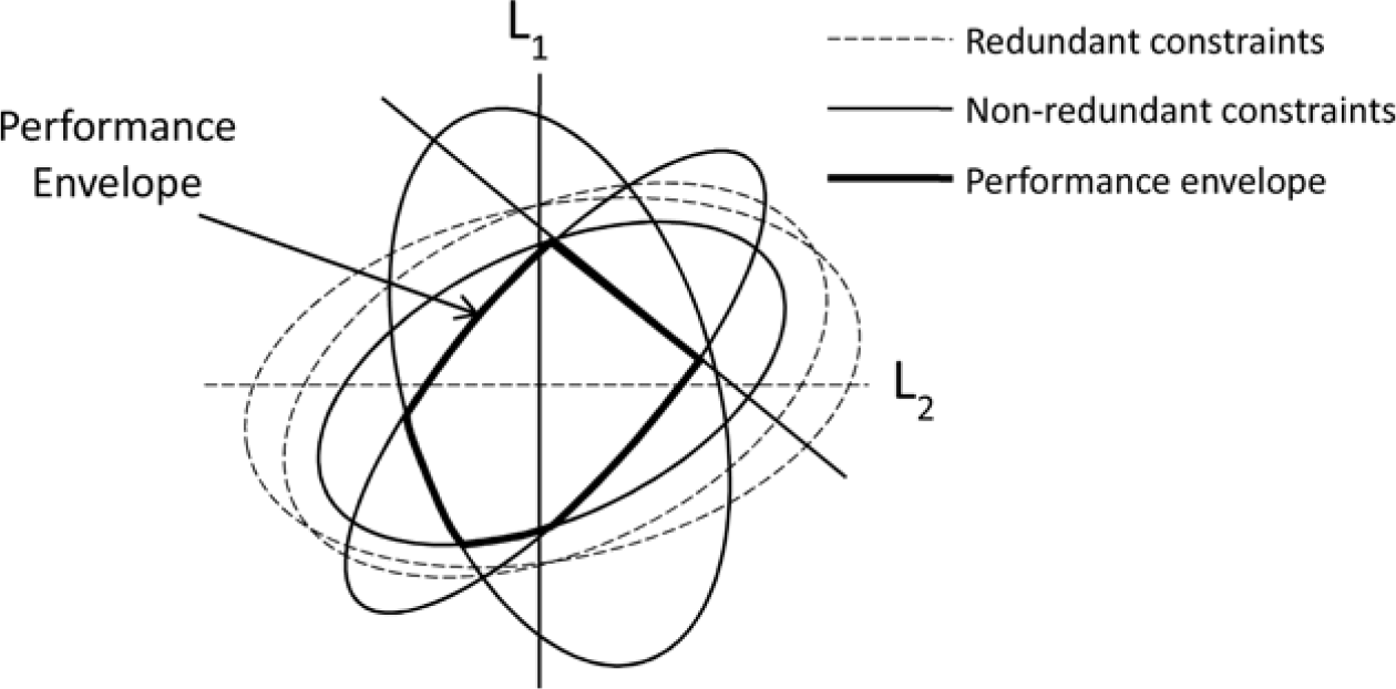
Consider a simple linear structure with bi-axial loading (loads L 1 and L 2) and six failure criteria, one of which is a linear function of the applied stress, e.g. a displacement constraint, and five of which are quadratic functions of the applied stress, e.g. material failure criterion (see Fig. 1). In load space each function remains in its original linear or quadratic form where the combination of L 1 and L 2 is sufficient to cause a state of stress/strain/deformation that violates the individual constraint. Thus, in Fig. 1 the region that is inside all the ellipses and the straight line is where all the RFs are >1. Note that only three ellipses and the straight line contribute to the boundary of this region, so the remaining two constraints are redundant. The performance envelope forming the boundary of this region identifies:
• A region in load space within which the structure can operate without failure,
-
• All possible modes of initial failure in the structure (the non-redundant constraints),
-
• The particular stress-sampling point which fails at any given combination of the loads, and its failure mode (the non-redundant constraints which are violated).
A performance envelope in 2D load space.

Now considering load cases, any combination of loading is represented by a point in the (L 1, L 2) load space. If this point lies inside the performance envelope i.e. the region of the boundary where
 $RF = 1$
, then the structure can carry the load without failure. Once the performance envelope is identified, the redundant structural constraints that do not form part of the envelope can be eliminated from the load case evaluation. This observation applies for any set of loads, but the computational cost will be large unless the number of load dimensions is small. In the examples that follow, the load space is three dimensional. In the first example, the performance envelope of a composite laminate is developed in a space defined by the
 ${N_x},{N_y},{N_{xy}}$
laminate loads. In the second example, which characterises the failure of an aerospace stiffened panel structural feature, there are many individual load cases, but it has been demonstrated(Reference Dharmasaroja, Armstrong, Murphy, Robinson, McGuinness, Iorga and Barron11) that these can be represented as the linear combination of three characteristic patterns of internal load, derived using SVD (singular value decomposition).
2.2 A performance envelope mesh
A representation of the performance envelope surface is required; however, its shape is initially unknown. One way of representing an unknown geometry is to sample a set of surface points to create an unorganised point cloud and connect each point into a set of polygons that assemble to represent the geometry. Many researchers have used spherical parametrisation to construct a mesh of an unorganised point cloud. For example, Gotsman et al.(Reference Gotsman, Gu and She12) introduced a combination of barycentric coordinates and spherical parametrisation, whilst Zwicker et al.(Reference Zwicke and Gotsman13) employed a spherical parametrisation to solve the re-meshing problem on a point cloud-based mesh. In this research, a similar concept will be employed where:
(1) An initial point cloud in spherical coordinates is sampled on a unit sphere with a regular point density. This is achieved by meshing a sphere with a mesh of triangular planar facets.
-
(2) The failure function is examined for each point in the mesh (which defines a direction from the origin) to find the radial distance at which the failure constraint is met.
-
(3) The unit points are transformed to the failure points.
-
(4) The performance envelope representation is formed by meshing the failure points. It is then assessed for its accuracy, and mesh refinement undertaken until the desired accuracy of the representation is achieved.
The following sub-sections outline each stage of the proposed approach in their noted order.
2.2.1 Unit point grid and mesh
A point grid is generated on a unit sphere with a set of predetermined spherical coordinate angles (
 $\phi $
and
 $\theta $
). The increment between each pair of angles determines how dense the initial point grid will be. In order to create a complete sphere of points the spherical coordinate angles are required to range from
 $0 \leq \phi \leq 2\pi $
and from
 $0 \leq \theta \leq \pi $
. The relationship between the spherical coordinates and their equivalent Cartesian coordinates is given by Equation (2), where r is the radius of the unit sphere (
 $r = 1)$
.
 \begin{equation}\left[ \begin{array}{c} x \\ y \\ z \end{array} \right] = r\left[ \begin{array}{c} {\sin \phi \sin \theta } \\ {\sin \phi \cos \theta } \\ {\cos \phi } \end{array} \right]\end{equation}
By computing the points in spherical coordinates the construction of a unit sphere surface mesh is straightforward. In this research, an unstructured triangle mesh is used because it offers significant flexibility(Reference Shewchuk14). However, at this stage it is worth noting that by employing the final adaptive refinement step, described below, the total computational effort to produce a final mesh envelope with a prescribed accuracy is not particularly sensitive to the initial unit sphere mesh density.
2.2.2 Failure function radial transformation
Once the unit sphere mesh has been generated, the failure function can be evaluated for each angle pair
 $(\phi ,\theta )$
. The goal is to solve for the
 $r$
value that satisfies failure, i.e.
 $RF = 1$
. The failure function, Equation (3), can be solved either numerically or analytically. The following examples herein demonstrate both numerical and analytical solution types.
 \begin{equation}f\left( {r,\phi ,{\textrm{}}\theta } \right) = 1\end{equation}
A piecewise-linear transformation can be applied to the domain using the determined
 $r$
values to radially transform the unit sphere points in the
 $r$
direction to new positions representing the
 $RF = 1$
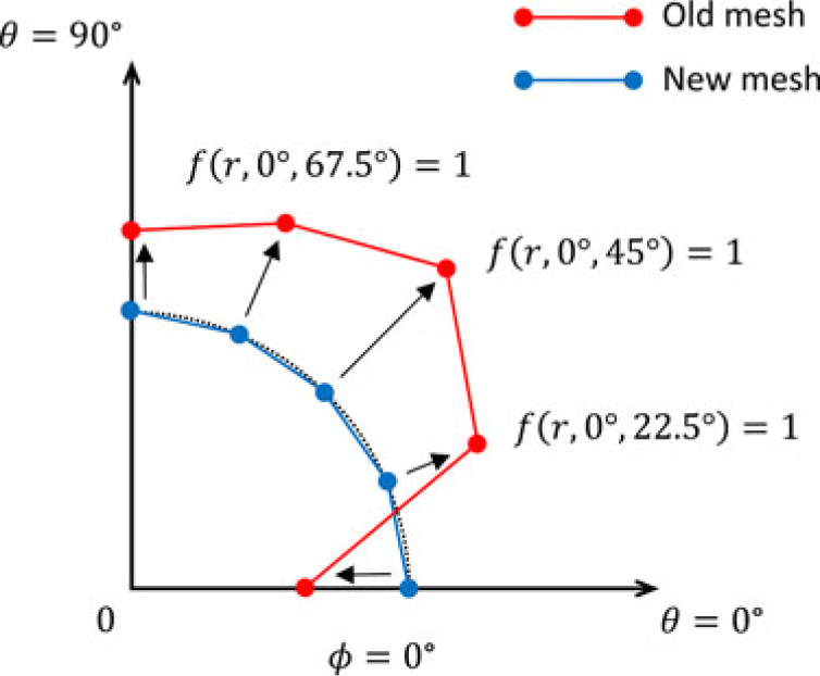
boundary. Figure 2 illustrates the radial transformation approach considering a 2D quarter section of an envelope on
 $\phi = \text{0}{^{\circ}}$
plane. The example illustrates five mesh grid points separated by equal
 $\theta $
intervals. As can be seen the transformation of the points is along a constant direction from the origin.
Illustration of mesh transformation in 2D, 1st quadrant.

2.2.3 Creating a performance envelope mesh
The transformed points may now be scattered around the load space. The original mesh connectivity may thus be updated by applying a convex hull algorithm(Reference Cheng, Dey and Shewchuk15). As the convex hull computes the smallest convex point set that encloses a given set of points this approach implies that the real performance envelope must be convex. The following examples demonstrate this to be the case for the range of textbook and industrial failure functions examined. However, work is currently underway that effectively removes this constraint. For the examples, the Quick-hull algorithm(Reference Barber, Dobkin and Huhdanpaa16) is used and for a 10,000 point problem in 3D the algorithm computes a hull within less than 0.004s on a standard PC.
This first performance envelope mesh may now be refined to guarantee that the envelope mesh lies within some known tolerance of the real envelope. Obviously there is a balance to be achieved, discussed below, between the computational burden of calculating and using the mesh, primarily defined by the number of mesh points(Reference Boissonnat, Mourrain, Rote, Vegter and Steiner17).
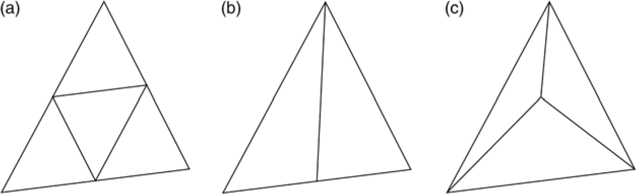
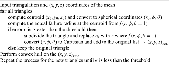
A great deal of research has been conducted on mesh refinement. One of the most common approaches is by mesh subdivision, Fig. 3. Subdivision algorithms insert an additional point into a mesh and locally refine the mesh connectivity in the region to include the new point. The location where the point is inserted will evidently influence the outcome of the process. This work adopts the insertion at the centroid of the triangle as it is the first trivial solution (see Fig. 3(c)). This approach has the advantage that it does not require any of the element bounding edges to be split, and so the refinement does not propagate to neighbouring elements.
Point insertion (a) on all edges (b) on one edge (c) at the centroid.

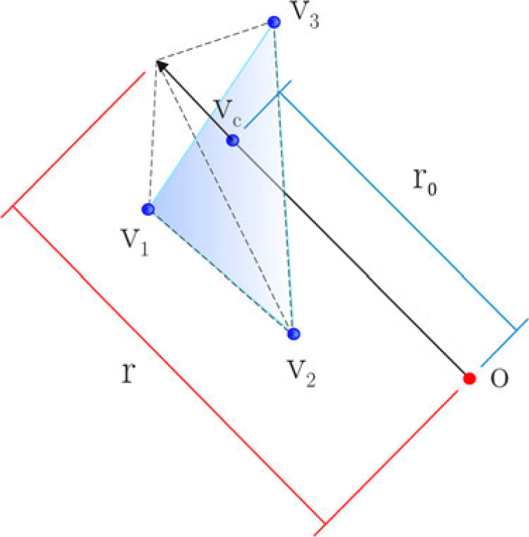
Mid-point refinement. If the RF at the centroid V c of a given triangle does not lie on the plane defined by V1, V2, V3 then an additional point V c is added to the mesh defining the performance envelope.

The approximation error between the real failure surface and a facet approximation may be established for any facet centroid, shown in Fig. 4, using the mesh points, Equation (4) and computing the centroid radius
 ${r_0}$
and angle pair (
 $\phi ,\theta $
). The centroid angle pair may then be used to directly calculate, from an evaluation of the failure function, the actual failure radius,
 $r$
. Figure 4 graphically illustrates this calculation. The figure depicts a single generic triangular facet which forms part of a performance envelope. In the figure, the corners of the facet are on a single plane and are denoted V1, V2, V3. The arrow in the figure represents a single orientation in load space, which defines a ratio of loading in each axis. The arrow passes through the centroid of the facet. The distance from the origin to the facet centroid is denoted as
 ${r_0}$
, and represents the facet’s approximation of the failure function (and therefore the performance envelope approximation) for the ratio of loads defined by the arrow orientation. The distance from the origin to the real failure surface (as calculated by the direct evaluation of the failure function) is notionally denoted by
 $r$
. Thus a facet centroid error can be defined using Equation (5). If this error is greater than a defined tolerance, the centroid radius and angle pair are added to the list of envelope mesh points. This will create a spike or an indent depending on the difference between the two radii as shown in Fig. 4. Performing the convex hull on the updated set of points gives a new triangulation of the convex surface. The entire process may then be repeated until the error at each facet is minimised. The algorithm is described in Algorithm 1.
 \begin{equation}{V_c} = {\frac{{V_1}}{3}} + {\frac{{V_2}}{3}} + {\frac{{V_3}}{3}}\end{equation}
 \begin{equation} \epsilon = {\frac{\left| {{r_0} - r} \right|}{r}}\qquad\end{equation}
Having outlined the approach to compute an appropriate performance envelope in load space, the following sections present example for performance envelope calculations. The first example considers analytical failure functions a composite laminate plate subjected to in-plane loading (representative of early conceptual design calculations).
Adaptive centroid refinement

3.0 PERFORMANCE ENVELOPE EXAMPLE BASED ON ANALYTICAL FAILURE FUNCTIONS
3.1 Structural analysis and failure functions
Classical laminate theory(Reference Daniel and Ishai18,Reference Jones19) can be used to describe the relationship between applied laminate plate loads and individual lamina stresses and strains, by assuming the following:
1. The material properties are the same at every point in an orthogonal axis of a lamina, and there exists a linear relationship between stress and strain.
-
2. The displacement is continuous through the thickness; normals to the mid-surface remain straight, unstretched and normal.
-
3. Each ply is in a state of plane stress with no delamination or inter-laminar effect.
With the additional assumptions that only laminate in-plane loads
 $({N_x},{N_y},{N_{xy}})$
are present and the laminate stacking sequence results in a bending-extension coupling matrix of insignificant magnitude, then the laminate loads can be related to the laminate mid-plane strains (
 ${\varepsilon_x},{\varepsilon_y},{\varepsilon_{xy}}$
) considering only the extensional stiffness matrix, [A], Equation (6). The local lamina stress (
 ${\sigma_1}$
,
 ${\sigma_2},\,{\tau_{12}}$
) in each ply coordinate system can be obtained using a transformation matrix (
 $T)$
in which
 $m = \cos \vartheta $
,
 ${\textrm{n}} = \sin \vartheta $
and
 $\vartheta $
is the local material orientation in each lamina, Equation (7). Thus, the relationship between the applied loads and local material axis stresses (
 ${\sigma_1}$
,
 ${\sigma_2},\,{\tau_{12}}$
) can be defined by a matrix
 $E = AT{Q^{ - 1}}$
, Equation (8).
 \begin{equation}\left[\begin{array}{c} {{N_x}} \\ {{N_y}} \\ {{N_{xy}}} \end{array}\right] = \left[ \begin{array}{c@{\ \ \ }c@{\ \ \ }c} {} & {} & {} \\ {} & A & {} \\ {} & {} & {} \end{array} \right]\left[ \begin{array}{c} {{\varepsilon _x}} \\ {{\varepsilon _y}} \\ {{\varepsilon _{xy}}} \end{array} \right]\qquad\qquad\qquad\qquad\qquad\qquad\qquad\qquad\qquad\qquad\quad\end{equation}
 \begin{equation}\left[ \begin{array}{c} {{N_x}} \\ {{N_y}} \\ {{N_{xy}}} \end{array} \right] = \underbrace {\left[ \begin{array}{c@{\quad }c@{\quad }c} {{A_{11}}} & {{A_{12}}} & {{A_{13}}} \\ {{A_{21}}} & {{A_{22}}} & {{A_{23}}} \\ {{A_{31}}} & {{A_{32}}} & {{A_{33}}} \end{array} \right]}_A\underbrace {\left[ \begin{array}{c@{\ \ \ }c@{\ \ \ }c} {{m^2}} & {{n^2}} & { - mn} \\ {{n^2}} & {{m^2}} & {mn} \\ {2mn} & { - mn} & {{m^2} - {n^2}} \end{array} \right]}_T\underbrace {{{\left[ \begin{array}{c@{\ \ \ }c@{\ \ \ }c} {{Q_{11}}} & {{Q_{12}}} & 0 \\ {{Q_{21}}} & {{Q_{22}}} & 0 \\ 0 & 0 & {{Q_{33}}} \end{array} \right]}^{ - 1}}}_{{Q^{ - 1}}}\left[ \begin{array}{c} {{\sigma _1}} \\ {{\sigma _2}} \\ {{\tau _{12}}} \end{array} \right]\quad\end{equation}
 \begin{equation}\left[ \begin{array}{c} {{\sigma _1}} \\ {{\sigma _2}} \\ {{\tau _{12}}} \end{array} \right] = \left[ \begin{array}{c@{\ \ \ }c@{\ \ \ }c} {} & {} & {} \\ {} & {{E^{ - 1}}} & {} \\ {} & {} & {} \end{array} \right]\left[ \begin{array}{c} {{N_x}} \\ {{N_y}} \\ {{N_{xy}}} \end{array} \right]\qquad\qquad\qquad\qquad\qquad\qquad\qquad\qquad\qquad\quad\ \ \ \end{equation}
The lamina stresses (or strains), which are typically the inputs to failure functions(Reference Daniel and Ishai18–Reference Marcelo, Volnei and Dirk23), are now described in the 3D laminate load space and using Equation (2) can be described in the spherical coordinate parameterization, Equation (9). Thus any failure function in terms of
 $f\left( {{\sigma _1},{\sigma _2},{\tau _{12}}} \right)$
can be transformed into
 $f\left( {r,\phi ,\theta } \right)$
and the failure radius
 $r$
(i.e.
 $f\left( {{\sigma _1},{\sigma _2},{\tau _{12}}} \right)\,{=}\,1$
) computed at any specified angle (
 $\phi ,\theta )$
.
 \begin{equation}\left[ \begin{array}{c} {{\sigma _1}} \\ {{\sigma _2}} \\ {{\tau _{12}}} \end{array} \right] = r\left[ \begin{array}{c@{\ \ \ }c@{\ \ \ }c} {} & {} & {} \\ {} & {{E^{ - 1}}} & {} \\ {} & {} & {} \end{array} \right]\left[ \begin{array}{c} {\sin \phi \sin \theta } \\ {\sin \phi \cos \theta } \\ {\cos \phi } \end{array} \right]\end{equation}
Three failure functions, with different characteristics, can be transformed into laminate global load space and combined to demonstrate the approach:
• The Tsai-Hill failure criterion does not distinguish failure modes and is calculated using a simple quadratic inequality, Equation (10)(Reference Daniel and Ishai18–Reference Tuttle20).
(10)
\begin{equation}f = {\left( {{\frac{{\sigma _1}}{X}}} \right)^2} + {\left( {{\frac{{\sigma _2}}{Y}}} \right)^2} + {\left( {{\frac{{\tau _{12}}}{S}}} \right)^2} + \left( {{\frac{{\sigma _1}{\sigma _2}}{{X^2}}}} \right) \le 1\end{equation}
-
• The maximum fiber stress criterion aims to predict fiber failure by comparing tensile or compressive applied fiber stresses with corresponding fiber strength properties, Equation (11)(Reference Daniel and Ishai18–Reference Tuttle20).
(11)
\begin{equation}f = {\sigma _1}/X \le 1\end{equation}
-
• The Puck failure criterion applies fracture plane stresses to establish matrix failure(Reference Puck and Mannigel24–Reference Puck and Schürmann26). The stress components involved in the failure are represented in terms of traction shear and normal stress on the fracture plane. Considering plane stress, the fracture plane stress components are described by Equation (12), where
$\alpha $
is the fracture angle(Reference Puck and Mannigel24).
(12)
\begin{equation}\left[ \begin{array}{c} {{\sigma _n}} \\ {{\tau _T}} \\ {{\tau _L}} \end{array} \right] = \left[ \begin{array}{c@{\ \ \ }c@{\ \ \ }c} 0 & {{{\cos }^2}\alpha } & 0 \\ 0 & { - \sin \alpha \cos \alpha } & 0 \\ 0 & 0 & {\cos \alpha } \end{array} \right]\left[ \begin{array}{c} {{\sigma _1}} \\ {{\sigma _2}} \\ {{\tau _{12}}} \end{array} \right]\end{equation}


Substituting Equation (9) into (12), the fracture plane stresses can be related to the load in spherical coordinates, Equation (13). Thus, a set of fracture plane stresses can be determined for a given load in spherical coordinates
 $\left( {r,\phi ,\theta } \right)$
. For the Puck failure equations(Reference Puck and Schürmann25), (Equation (14) for the matrix under compressive loading (
 ${\sigma _2} < 0$
); Equation (15) for the matrix under tensile stress (
 ${\sigma _2} > 0$
)) require the fracture angle
 $\alpha $
to be calculated to find the angle
 ${\alpha _0}$
at which the material is weakest. Only then can failure in each ply be evaluated and the first ply failure found(Reference Puck and Schürmann26).
 \begin{equation}\ \ \left[ \begin{array}{c} {{\sigma _n}} \\ {{\tau _T}} \\ {{\tau _L}} \end{array} \right] = r\left[ \begin{array}{c@{\ \ \ }c@{\ \ \ }c} 0 & {{{\cos }^2}\alpha } & 0 \\ 0 & { - \sin \alpha \cos \alpha } & 0 \\ 0 & 0 & {\cos \alpha } \end{array} \right]\left[ \begin{array}{c@{\ \ \ }c@{\ \ \ }c} {} & {} & {} \\ {} & {{E^{ - 1}}} & {} \\ {} & {} & {} \end{array} \right]\left[ \begin{array}{c} {\sin \phi {\textrm{}}\sin \theta } \\ {\sin \phi \cos \theta } \\ {\cos \phi } \end{array} \right]\end{equation}
 \begin{equation}f = {\left( {{\frac{{\tau _T}}{{S_T} - {\mu _T}{\sigma _n}}}} \right)^2} + {\left( {{\frac{{\tau _L}}{{S_T} - {\mu _L}{\sigma _n}}}} \right)^2} \le 1\qquad\qquad\qquad\quad\ \ \ \end{equation}
 \begin{equation}f = {\left( {{\frac{{\sigma _n}}{{Y_t}}}} \right)^2} + {\left( {{\frac{{\tau _T}}{{S_T}}}} \right)^2} + {\left( {{\frac{{\tau _L}}{{S_L}}}} \right)^2} \le 1 \qquad\qquad\qquad\qquad\qquad\end{equation}
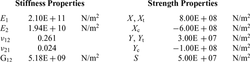
The meaning of the material properties in Equations (13) and (14) and the values used in the study are defined in Table 1. Each of these failure criteria clearly exhibits a different analytical calculation. Thus, assuming an eight-ply composite laminate [0/90/±45]s and representative lamina material properties, Table 1, it is possible to create example performance envelopes for each criterion.
Composite laminate properties

3.2 Performance envelope results
Considering first the Tsai-Hill criterion, Equation (10) implies that the failure envelope of a ply is a quadratic function of
 ${\sigma _1},{\sigma _2}$
and
 ${\tau _{12}}$
and therefore forms an ellipsoidal shape in
 ${\sigma _1},{\sigma _2},{\tau _{12}}$
stress space or
 ${N_x},{N_y},{N_{xy}}$
stress resultant space.
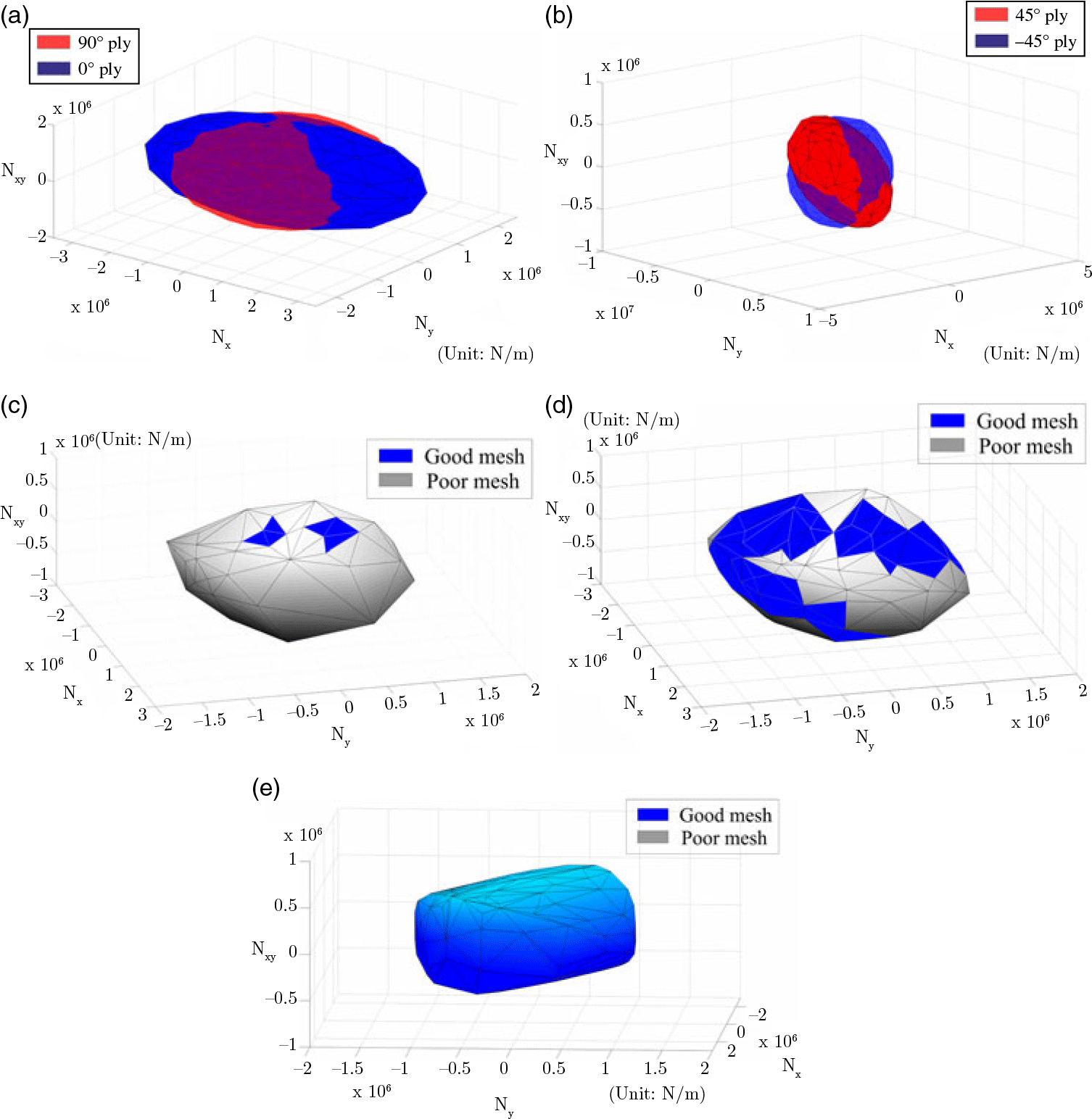
Even though the failure equation is not physically based, it does provide insight into the material behaviour. For example, the 0° ply allows more load in the longitudinal direction of the laminate whereas the 90° has more transverse strength, Fig. 5(a). The envelopes of the 45° and −45° plies are identical (to within the accuracy of the facetted representation) in the
 ${N_x},{N_y}$
plane when shear is zero; when the shear load is involved, they are aligned in the maximum shear directions, as can be seen in Fig. 5(b).
Tsai-Hill laminate envelope for a [0/90/±45]s laminate with the properties given in Table 1. (a) Tsai-Hill load envelopes of
 $\text{0}^{\circ}$
and
 $\text{90}^{\circ}$
plies (b) Tsai-Hill load envelopes of
 $\text{45}^{\circ}$
and
 $-\text{45}^{\circ}$
plies (c) Tsai-Hill laminate envelopes, 1st refinement (d) Tsai-Hill laminate envelopes, 3rd refinement (e) Tsai-Hill laminate envelopes, 6th refinement.

These envelopes are based on an initial unit sphere mesh of 30 uniformly distributed points. Integrating the lamina envelopes into a single laminate envelope is first illustrated in Fig. 5(c), again based only on an initial unit sphere mesh of 30 uniformly distributed points. Clearly mesh refinement is required with poor-quality facets identified in grey (identifying a difference > 5% between the mesh radius and the actual radius at the centroid). Figure 5(d) presents a third refinement iteration and Fig. 5(e) presents the final Tsai-Hill performance envelope containing only good-quality facets (radius errors <5%), which is obtained after six iterations. This final envelope considers all the possible combinations of the three in-plane loads and the non-redundant Tsai-Hill failure modes. The envelope mesh represents the curved geometry within the specified <5% tolerance and the entire construction process took 80s when performed using a symbolic toolbox in MATLAB, installed on a Windows 7 PC with Quad-core Intel i7 processor and 16 GB of memory.
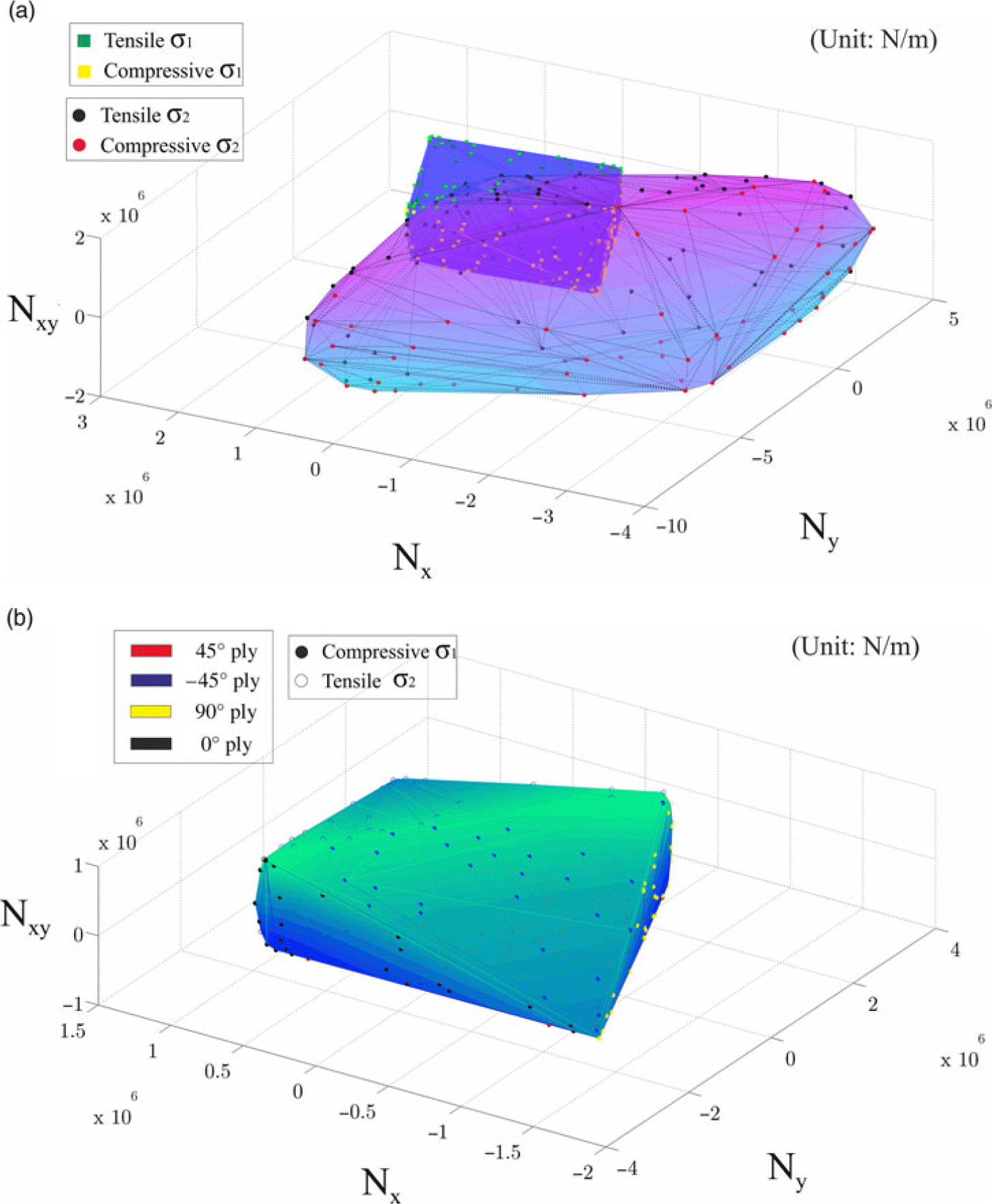
Different failure criterion can also be evaluated simultaneously. To demonstrate this, fibre failure using Equation (11) and matrix failure using Equations (14) and (15) are next examined. The same composite laminate properties and unit sphere with 30 initial points were used as for the Tsai-Hill criterion. Figure 6(a) displays the result when the two envelopes are placed together. Even though there are four failure modes in the figure, only fibre compression and matrix tensile are important because they have the smallest load radius. When the two envelopes are integrated the inner surface, which consists of only the critical criteria, can be formed as displayed in Fig. 6(b). Each point on the surface identifies the most critical failure mode and location (ply). During the construction, four different levels of data namely modes of failure, laminate, ply stresses and fracture angles, were evaluated. The time used for constructing the entire envelope where the error threshold of each facet was set at 2.5%, was 7.5min. If the error threshold was increased to 5%, the time was reduced to only 5min. As the envelope uses the symbolic toolbox in MATLAB, the calculation time may be accelerated by using a more advanced numerical solving method. Once an envelope is computed for a given laminate, it is extremely rapid to evaluate whether any applied load combination results in an RF of
 ${<}1$
, as demonstrated in the following sections.
Mixed failure mode envelope for a [0/90/±45]s laminate with the properties given in Table 1. (a) Fibre and Matrix performance envelopes for a laminate (b) Combined Fibre and Matrix performance envelopes for a laminate.

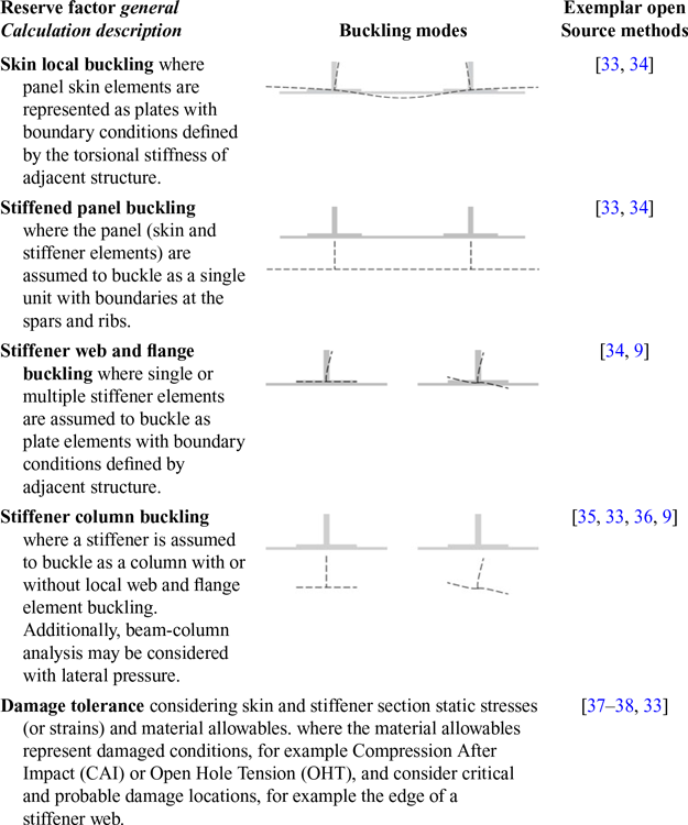
Typical preliminary design reserve factor calculations for stiffened panels

4.0 PERFORMANCE ENVELOPE EXAMPLE USING BLACK-BOX FAILURE EVALUATION
4.1 Structural analysis and failure functions
A failure analysis tool which is used in the preliminary design stage for major aircraft composite structures was provided for this research as an executable file. The tool analyses stiffened panel features for buckling and other failure modes using the idealisation presented in Fig. 7. These are sometimes called super-stiffeners. The tool is built to solve specific problems for structural sizing and optimisation, e.g. Iorga et al.(Reference Iorga, Malmedy, Stodieck, Coggon and Loxham7). Thus the tool represents a single portion of a larger industrial workflow for the design and optimisation of major aerospace components. The loading conditions, material and geometric properties of the stiffened panel are the initial inputs to the tool; based on these the tool returns a series of Reserve Factor (RF) values. The mathematical calculations performed by the tool are proprietary and incorporate empirical data and aspects of conventional design practice that could not be used directly or indirectly to support performance envelope creation. Each stiffened panel in a wing or fuselage structure has different material and geometric properties, but once these have been defined the tool can be queried for the RF resulting from any arbitrary loading. Typically, at the preliminary design stage a small number of broad ranging RFs would be examined for a stiffened panel component. Table 2 illustrates a range of representative structural RFs failure modes and provides references to formulae in the open literature. The table includes buckling and damage tolerance assessments appropriate for stiffened panel component preliminary design.
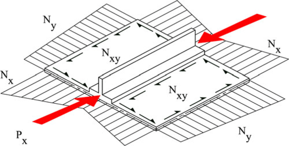
Thus this example has a number of additional challenges not encountered within the first example: Firstly, the failure of a stiffened panel is a function of seven internal loads on the structural element, as shown in Fig. 7, Equation (16); Secondly, the function is mathematically inaccessible and must be treated as a procedural function or black box; Thirdly, the number of failure mode requests is defined by an input flag. The smallest possible flag gives four RF values simultaneously; Finally, there exists a minimum time per function call, which is high compared to the time for solving polynomial equations on a standard PC using a numerical method. A series of strategies were developed and employed to overcome these real-world practical difficulties, and these are described next.
 \begin{equation}RF\, = \,f\left( {{{\left\{ {{N_x},{\textrm{}}{N_y},{N_{xy}}} \right\}}_{Right\ side{\textrm{}}}}{\textrm{}}{{\left\{ {{N_x},{\textrm{}}{N_y},{N_{xy}}} \right\}}_{Left\ side{\textrm{}}}}{{\left\{ {{P_x}} \right\}}_{Stiffener{\textrm{}}}}} \right)\end{equation}
4.1.1 Dimensional reduction of the load space
In Dharmasaroja et al.(Reference Dharmasaroja, Armstrong, Murphy, Robinson, McGuinness, Iorga and Barron11) a wing GFEM was examined considering 274 external load cases, including flight manoeuvre, gust, landing, take-off and ground loading events. On the wing, 6 force and moment loads were applied at a total of 27 positions along the structure. In the study reported here the 274 external load cases were analysed and the stiffened panel internal loads extracted. These matched the loads required by the black-box analysis tool, as defined in Fig. 7 and Equation (16). The calculated internal loads were then used to construct a matrix of the internal loads
 $\textbf{\textit{A}}$
. This internal load matrix had 274 rows, representing the 274 applied load cases, and 7 columns, representing the 7 extracted internal stiffened panel loads(Reference Dharmasaroja27).
Load components on an idealised stiffened panel.

Using the well-known matrix technique of Singular Value Decomposition (SVD) the matrix
 $\textbf{\textit{A}}$
was factorised as
 \begin{equation}{\textbf{\textit{A}}} = \textbf{\textit{US}}{\textbf{\textit{V}}^{\textbf{\textit{T}}}}\end{equation}
A reduced-rank loads matrix can be derived which approximates the original internal loads matrix as
 \begin{equation}{\textbf{\textit{A}}} \approx {{\textbf{\textit{A}}}_{\textbf{\textit{k}}}} = {{\textbf{\textit{U}}}_{\textbf{\textit{k}}}}{{\textbf{\textit{S}}}_{\textbf{\textit{k}}}}{\textbf{\textit{V}}}_{\textbf{\textit{k}}}^{\textbf{\textit{T}}} = {{\textbf{\textit{U}}}_{\textbf{\textit{k}}}}{\textbf{\textit{L}}}{\textrm{}}\end{equation}
where
 $\textbf{\textit{L}}$
will be called the characteristic loads matrix(Reference Dharmasaroja27).
The SVD decomposition established that the 274 load cases
 $\times\, 7$
DOF can be reduced to
 ${U_k}\, (274 \times 3)$
and
 ${L_k}\, (3 \times 7)$
matrices, i.e. there were only 3 characteristic loads for a stiffened panel. In other words,
 $\textbf{\textit{L}}$
represents three characteristic patterns of the seven internal loads. The internal loads corresponding to any external wing loading can be represented as a linear combination of these three.
 ${\textbf{\textit{U}}_{\textbf{\textit{k}}}}$
represents 274 points in 3D characteristic load space corresponding to all wing external load cases. This process for the dimensional reduction of the load space is further described in Dharmasaroja(Reference Dharmasaroja27).
Normally the reserve factor for each potential failure mode would be checked for each of the 274 load cases, requiring individual GFEM calculations to obtain the internal loads for a failure evaluation using the black-box analysis tool. However, in this reduced load space the performance envelope is the surface where RF = 1. Thus by forming the performance envelope in the reduced load space it becomes possible to use linear combinations of the characteristic loads to assess any external load case against the performance envelope. With three characteristic loads only three internal load calculations need to be performed to enable any external load case to be represented and compared with the performance envelope (and the failure functions it represents).
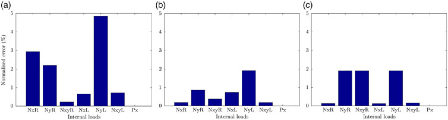
To assess the accuracy of this process, the stiffened panel loads and performance envelopes were analysed under a representative sample of one hundred flight and ground external loading cases(Reference Dharmasaroja, Armstrong, Murphy, Robinson, McGuinness, Iorga and Barron11). For three stiffened panels (one at the GFEM wing root, one at the mid-span and one at the wing tip) characteristic loads were identified and used to recreate the loads resulting from the one hundred external load cases. The errors were then calculated considering the original stiffened panel loads and the reconstructed loads. The maximum normalised load errors of all the hundred cases are displayed in Fig. 8(Reference Dharmasaroja27). None of the reconstruction errors is greater than 5%, thus creating a performance envelope in its identified characteristic load space for a stiffened panel in a wing.
Maximum normalized error on each stiffened panel for the left and right panel stress resultants and the stiffener axial load, expressed as a percentage. (a) Wing root (b) Wing mid-span (c) Wing tip.

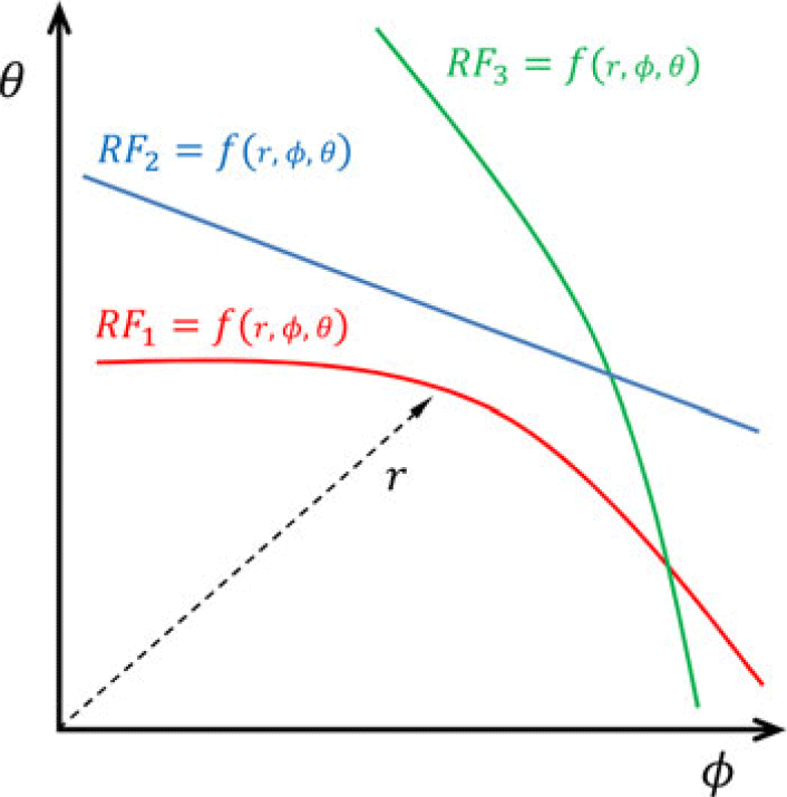
Multi-constraint optimisation illustration in spherical coordinates
 $(\phi ,\,\theta )$
.

4.1.2 Function evaluation
Since the calculations required to find the RFs are not accessible, a numerical method must be used to find the solution where RF = 1. However, the tool requests at least four RF mode types per analysis. For this reason, it is not efficient to individually determine only a single RF mode type at a time. The problem can be reformulated as a multi-constraint optimisation. Figure 9 illustrates the multi-constraint optimization problem with three RF constraints. Herein four optimization solvers were tested: interior point, trust region reflective, SQP and active set(28). The SQP and active set solvers performed best with the active set found to be relatively quick, as it takes larger steps towards optimisation, but SQP was found to be more robust, always converging for every load angle input.
4.2 Performance envelope results
A study was conducted on the mid-span stiffened panel examined in Section 4.1.1. Calculations were performed considering the three identified characteristic loads (labelled
 ${U_1}$
,
 ${U_2}$
,
 ${U_3}$
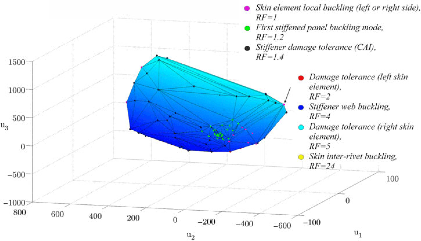
). Seven failure criteria were requested from the analysis tool. Although the details of the failure criteria calculations were not available a general title for each calculation was given as part of the analysis output. The calculations included buckling and damage tolerance criteria. For a reader unfamiliar with aircraft stiffened panel design Refs (Reference Niu8) and (Reference Niu9) provide appropriate background on relevant buckling and damage tolerance criteria. The initial envelope in the first iteration was morphed from a unit sphere with 30 mesh points, as in the first example. It then underwent ten refinement processes in which the subdivision occurred at the centroids of the triangles with unacceptable errors. The final envelope in the 11th refinement is shown in Fig. 10. Similar to the laminate performance envelope, the failure surface is formed by different failure modes. In Fig. 10 the colour of the mesh points denotes the critical failure mode, and for a single point the complete list of calculated RFs at the surface are presented. For this example, the envelope construction time with a threshold error of 5% was approximately 50min (when performed using MATLAB, installed on a Windows 7 PC with Quad-core Intel i7 processor and 16 GB of memory). Figure 11 demonstrates how a performance envelope enables the identification of the non-redundant binding constraints of a structural feature.
Procedural performance envelopes of different structural elements.

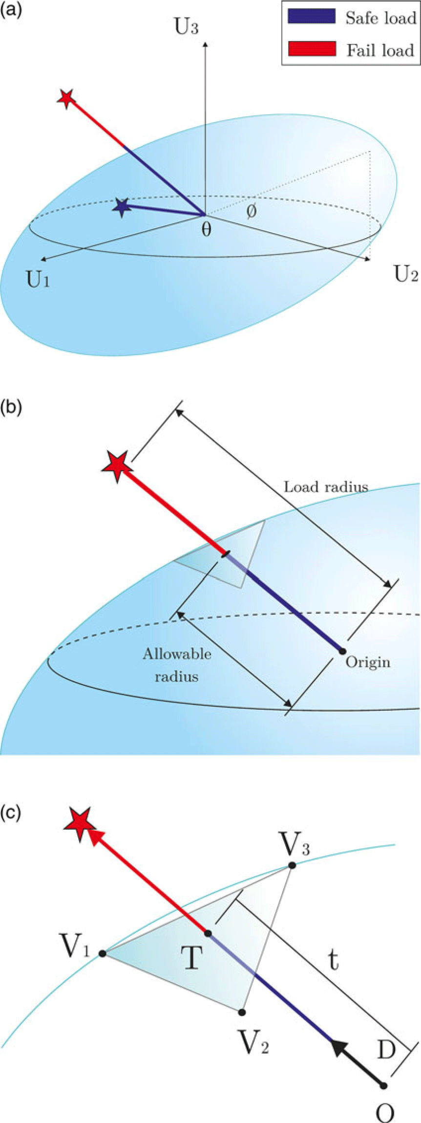
RF estimation using a performance envelope. (a) Performance envelope and two arbitrary loads (b) allowable radius and load case radius (c) Triangle ray intersection.

5.0
$\textit{RF}$
ESTIMATION USING PERFORMANCE ENVELOPES

Once a performance envelope has been created, it may be used for rapid failure evaluation. Figure 11(a) illustrates plotting two arbitrary load cases in a load space containing a performance envelope. The load case residing within the performance envelope
 $\left( {r,\phi ,\theta } \right)$
has an RF greater than 1 (a safe load) while the load case lying outside the envelope will cause structural failure (RF < 1). For a given pair of load angles
 $\left( {\phi ,\theta } \right)$
, the envelope is defined by a vector from the origin to the point of intersection with the envelope boundary. The vector radius is labelled the allowable radius
 ${r_{allowable}}$
, Fig. 11(b). Assuming the load radius is a linear function of the applied loads then the RF for any load case with the same load angles can be calculated using Equation (19).
 \begin{equation}RF = {\frac{{\textrm{load to cause failure}}}{{\textrm{applied load}}}} \cong {\left( {RF} \right)^{\sim}} = {\frac{{r_{allowable}}}{{r_{applied}}}}\end{equation}
If the load radius is not a linear function of the applied loads, then Equation (19) is a first-order approximation of the RF in the area of interest, i.e. close to the failure surface where RF = 1.
5.1 Ray triangle intersection
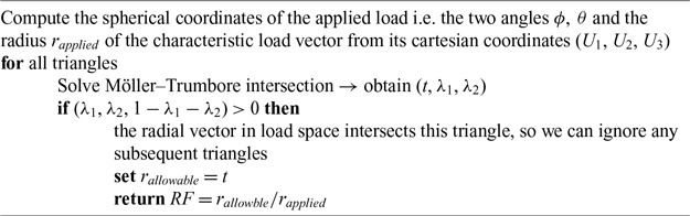
For a performance envelope formed by a triangular mesh, each triangle represents a region in load space where it is assumed RF = 1. For a given direction in load space, the load corresponding to RF = 1 is a vector from the origin to the point of intersection with one of the triangles. In computer-graphics, this vector-plane intersection problem is called ray tracing, and it is used to project the light source to a 3D object for rendering(Reference Glassner29). Möller and Trumbore(Reference Möller and Trumbore30) introduced a simple and efficient ray-triangle intersection algorithm for the triangle mesh as described in Fig. 11(c). Principally, the algorithm solves three linear equations to determine the distance (
 $t$
) from the origin (
 $O$
) to the plane defined by the triangle and the barycentric coordinates
 $\left( {{\lambda _1},{\lambda _2}} \right)$
of the intersection point (
 $T$
). If the intersection point is inside the triangle then all three barycentric coordinates of the triangle
 $\left( {{\lambda _1},{\lambda _2},1 - {\lambda _1} - {\lambda _2}} \right)$
are greater than 0. The vector (
 $D$
), which defines the direction of the vector from the origin, can be found from the three components of the characteristic load vector corresponding to a given load case. The corresponding RF is computed as described in Algorithm 2.
Fast RF using Möller-Trumbore algorithm

This method checks the ray against every triangle. For the envelope application where the number of triangles is significantly less than in a computer graphics application, this algorithm allows the calculation of allowable radius in a negligible amount of computational time, discussed next along with results. When the number of points or triangles is extremely large, a more refined algorithm such as a k-d tree(Reference Bentley31), which organises points in k-dimensional space to facilitate rapid searching, might be considered as an alternative.
5.2 Reserve factor calculation results
Again, the study was conducted on the mid-span stiffened panel examined in Section 4.1.1. The three identified characteristic loads (labelled
 ${U_1}$
,
 ${U_2}$
,
 ${U_3}$
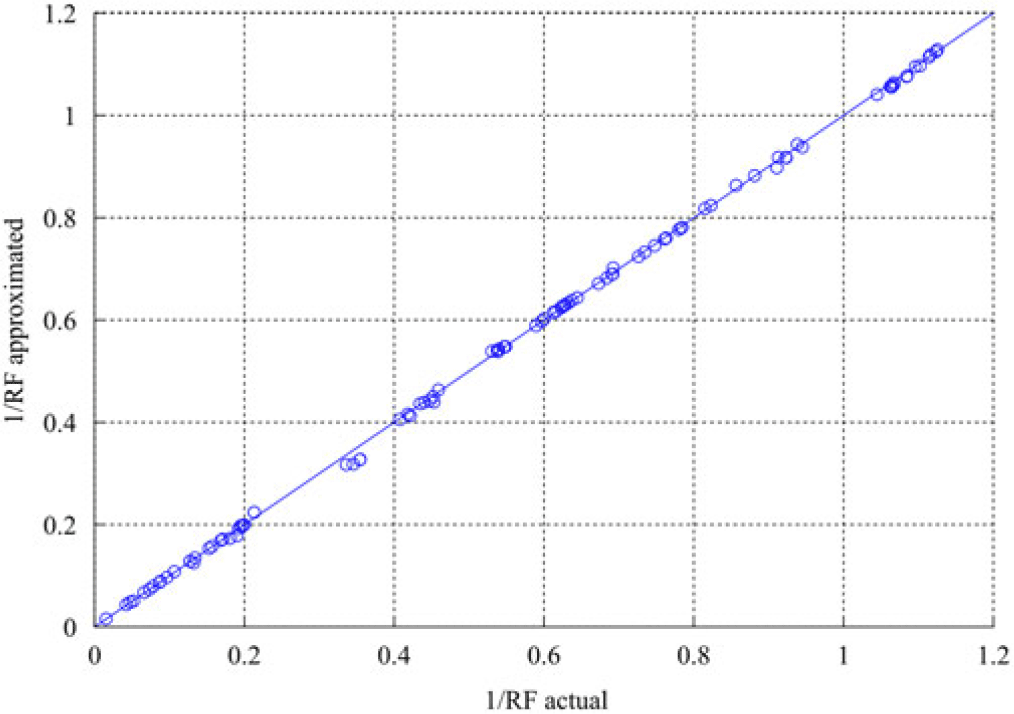
) for the 100 internal load cases were intersected against the previously created performance envelope (Section 4.2, Fig. 10). The estimated RFs where then compared against the actual RFs obtained by running the analysis tool directly. Figure 12 displays the combined results, plotting the estimated RF values (vertical axis) against the actual RF values (horizontal axis). Note that 1/RF values are plotted, since large RF values are of less interest than smaller RF values. Note also that the structure has not been accurately sized, such that RF < 1 (i.e. 1/RF > 1) are present, enabling the method to be fully tested.
Comparison of RF values approximated with the performance envelope with direct calculation using the analysis tool.

The plot indicates that all the RFs were accurately estimated from the performance envelopes throughout the range. The maximum error is around 0.5%, which is five times less than the refinement threshold set when creating the envelope. The computational time to create the estimated RF values was essentially negligible. For 100 load cases, the intersection operation time with 256 facets took approximately 0.001s. Moreover, increasing the number of load cases does not significantly increase the computational burden; for example, using the same performance envelope, calculating the critical RFs of 104 random load values required only 0.08s.
5.3 Computational effort
Given the insignificant computational burden to estimate RF values from a performance envelope (Section 5.2) but the considerable computational burden to create a performance envelope (Section 4.2), this section focuses on the construction of the performance envelope.
5.3.1 Relaxing the performance envelope threshold
In Section 5.2 the error introduced by the mesh scarcely influences the RF calculation. As a result, the mesh refinement error threshold, which was set at 5%, can be relaxed to reduce the total computational time. Increasing the threshold error from 5% to 10%, the envelope construction time is reduced from approximately 50 to 20min. Examining the new RF approximations from the envelope show a negligible effect from the mesh coarsening. This result is interesting and implies that the threshold error for the mesh refinement should be adjusted based on the RF approximations rather than the performance envelope if the sole purpose of the performance envelope is to approximate RF values.
5.3.2 Ellipsoid scaling
Considering the performance envelopes in Figs 5, 6 and 10 their shapes are closer to ellipse-like geometry than a sphere. The transformation of the mesh on a unit sphere to these envelopes thus results in many poorly shaped triangles. As a result, attempting to refine the mesh directly from such an initial mesh requires substantial effort. A new method which creates an optimised space for the mesh is thus proposed.
The ellipsoid approximation algorithm introduced in Li and Griffiths(Reference Li and Griffiths32) generates a transformation matrix that may be used to transform the points in 3D Cartesian coordinates on a unit sphere to create a best-fit ellipsoid. This approach approximates the ellipsoid from the initial envelope iteration and then embeds the effect on the original load space. The use of the more suitable load space means better triangle shapes are initially created and these are more suitable for refinement to represent the ellipsoid shape of the envelope. Additionally, by only changing the load space the previously described mesh refinement method can be effectively applied and triangular meshes refined to fit the ellipsoid performance envelope shape.
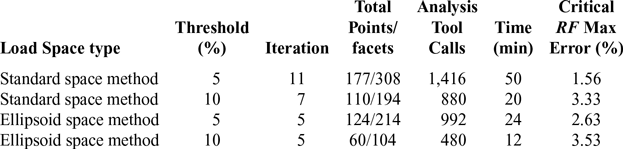
Table 3 presents indicators that can be used to measure the computational effort required for the construction of a performance envelope. These include the number of iterations required to meet the specified error threshold, the number of points and facets in the final constructed envelope, the average number of analysis tool queries used in the creation of the envelope, and the total time for constructing the envelope.
Computational effort of various envelope construction approaches

Examining the results in Table 3 the standard method that gradually refines the triangle from the initial coarse mesh is less efficient than the ellipsoid space method which requires only five iterations. When increasing the triangle threshold by 10% for the ellipsoid space method, the number of black-box tool calls was reduced to 60 points and gave 3.53% maximum RF errors for the critical value. The total construction time was around 12min.
6.0 CONCLUSIONS
A robust method for constructing a performance envelope has been established and demonstrated. The method is based on the concept of spherical parametrisation and adaptive mesh refinement. The method initially generates the spatial angles around a unit sphere mesh. The unit sphere mesh points are moved in the radial direction and form a surface mesh defining the performance envelope. The adaptive mesh refinement gradually refines the initial coarse mesh until the representation error is below a desired threshold.
Two demonstration case studies illustrate that a performance envelope in three-dimensional load space is adequate for capturing the failure behaviour of complex structural elements (a composite laminate considering standard analytical failure functions, and a stiffened panel considering industrial analysis tools). The case studies also demonstrate that a performance envelope is potentially useful in fast reserve factor estimation, redundant constraint elimination and identifying the binding constraints that are effectively designing a structural feature. The estimation of RFs of multiple load cases is demonstrated to be rapid, though the construction of a performance envelope requires the upfront cost of modelling the surface where
 $RF = 1$
. The demonstration case studies also establish that initially ellipsoid-shaped performance envelopes are suitable for effective mesh refinement.
The proposed approach will be most useful for structures with a very large number of load cases, where the cost of reconstructing the envelope for a given structural feature may be offset against the number of load cases requiring examination. In operations, a constructed performance envelope defines an effective digital twin model for a structural feature, enabling rapid evaluation of load exceedance, and the rapid identification of structural features which require inspection, maintenance or repair.
ACKNOWLEDGEMENTS
Financial support from Airbus UK for the PhD research of A. Dharmasaroja is gratefully acknowledged.