
I. INTRODUCTION
The larger tensile residual stress can be induced by the machining and manufacturing process, e.g., the high-energy pulsed-laser technology Reference Chao, Wei and Liang1,Reference Eto, Miura, Tani and Fujii2 and the welding process. Reference Aoki, Nishimura and Hiroi3,Reference Katsuyama, Yamaguchi, Li and Onizawa4 Under this condition, the fatigue lives of workpieces could be shortened Reference Cho, Yang, Son and Kim5–Reference Sasahara7 by means of increasing the fatigue crack growth rate. Reference Ilman, Kusmono and Iswanto8,Reference Pouget and Reynolds9 So how to relieve the local larger tensile residual stresses in the workpieces induced by the machining and manufacturing process, e.g., the high-energy pulsed-laser technology and the welding process, has become an important topic in the industrial community.
At present, the residual stress relieving technologies mainly include the thermal stress relief (TSR) Reference Edwards and Ramulu10 and the vibratory stress relief (VSR). Reference Shalvandi, Hojjat, Abdullah and Asadi11–Reference Walker, Waddell and Johnston13 The TSR belongs to the conditional stress relieving technology compared with the VSR, in which the treated workpiece was placed in the annealing furnace to be heated up to the annealing temperature. Meanwhile, the treated workpiece need to hold definite times at the annealing temperature followed by a desired rate of cooling. Under this condition, the residual stress in the workpiece can be eliminated with the help of the controlled temperature field. Furthermore, the VSR belongs to the energy conservation relieving technology compared with the TSR, in which the treated workpiece was excited at its resonant frequency for about 30 min. Under this condition, the vibration energy can be absorbed by the microdefects inside the materials, e.g., the dislocations. As a result, the residual stress in the workpiece, as expected, can be eliminated with the aid of the vibration field. Based on the residual stress relieving mechanisms of the TSR and the VSR, we believe that the external energy imposed into the workpiece is the essence of the residual stress relieving since the thermal energy and the vibration energy can be effectively absorbed by the microdefects. Under this condition, it can be concluded that the residual stress in the workpiece can be relieved if the external energy can be directly imposed into the materials. The effects produced by the electric current pulse (ECP) technology on the materials had already been studied, and the significant electroplasticity (EP) effect had been found in these studies. Reference Kozlov, Mordyuk and Chernyashevsky14–Reference Zuev, Gromov and Gurevich19 Under this condition, the flow stress of the materials is reduced. Reference Kim, Vinh, Yu, Hong, Lee, Kim, Han and Roth20 In other words, the maximum resistance for the dislocation motion can be reduced when the materials are exposed on the electric field, which implies that the electrical energy can be effectively absorbed by the microdefects inside the materials. So it can be concluded that the ECP technology can be applied to eliminate the residual stress in the workpiece. Meanwhile, this residual stress relieving technology can be called as the ECP stress relief.
In this study, the high-energy oscillating ECP technology was introduced to relieve the local residual stresses in the AISI 1045 steel treated by the pulsed-laser surface irradiation based on the Nd:YAG pulsed-laser machine. Furthermore, the EP model was developed based on the thermal activation theory to reveal the mechanism of the high-energy oscillating ECP stress relief.
II. MECHANISM OF THE HIGH-ENERGY OSCILLATING ECP STRESS RELIEF
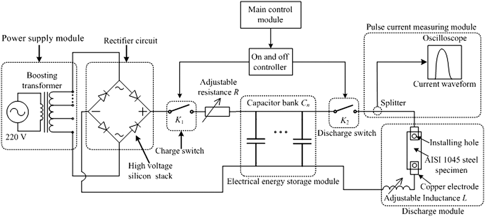
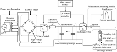
The high-energy oscillating ECP imposed into the specimen plays an important role in activating the dislocation motion along the slip plane. Figure 1 shows the experimental system of the high-energy oscillating ECP stress relief designed for this study. Reference Zheng, He and Shi21 This system mainly consists of a power supply module, a rectifier, a main control module, an electrical energy storage module, a pulse current measuring module, and a discharge module. In the power supply module, the boosting transformer is used to amplify the input voltage to improve the oscillating ECP energy imposed into the specimen, which is the alternating current (AC) with the voltage of 220 V. In the rectifier circuit, the high voltage silicon stack is adopted to convert the AC into the direct current to recharge the capacitor bank C n . The main control module is used to control the on and off controller to control the charge process and the discharge process of the capacitor bank. The electrical energy storage module is mainly composed of a series of capacitors to store the electrical energy. The pulse current measuring module is used to measure the pulse current waveform. The stored electrical energy in the capacitor bank is imposed into the specimen in the discharge module to relieve the residual stress in the specimen by activating the dislocation motion.
The experimental system of the high-energy oscillating ECP stress relief.

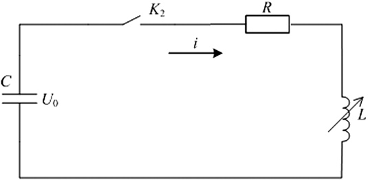
The specimen is connected to the discharge module by the two copper electrodes shown in Fig. 1 and the high-energy oscillating ECP can be imposed into the specimen. To reveal the generation process of the high-energy oscillating ECP in the discharge module, the discharge module can be equivalent to the following discharge circuit shown in Fig. 2. In Fig. 2, the voltage U 0 is the discharge voltage of the capacitor bank, the C is the capacitance of the capacitor bank, the K 2 is the discharge switch, the resistance R is the equivalent resistance of the discharge module mainly consisted of the resistance of the specimen and the resistance of the discharge circuit, and the adjustable inductance L is used to adjust the waveform of the high-energy oscillating ECP. The discharge circuit is the RLC series circuit of the two order mathematical model. According to the Kirchhoff's current law (KCL), the Kirchhoff's voltage law (KVL), and the volt–ampere characteristics of circuit components, the equation of the discharge circuit can be given as
 $$Ri + L{{{\rm{d}}i} \over {{\rm{d}}t}} + {1 \over C}\int i \,{\rm{d}}t = {U_0}\quad ,$$
and the equation can be converted into the following second order linear constant coefficient differential equation
 $$LC{{{{\rm{d}}^2}i} \over {{\rm{d}}{t^2}}} + RC{{{\rm{d}}i} \over {{\rm{d}}t}} + i = 0\quad .$$
The schematic of the equivalent discharge circuit of the discharge module.

The damping coefficient can be assumed as
 $\zeta = {R \over 2}\sqrt {{C \over L}}$
and the undamped oscillating angular frequency can be assumed as
 ${\omega _n} = {1 \over {\sqrt {LC} }}$
. In this case, the equation of the discharge circuit can be further obtained as
 $${{{{\rm{d}}^2}i} \over {{\rm{d}}{t^2}}} + 2\zeta {\omega _n}{{{\rm{d}}i} \over {{\rm{d}}t}} + \omega _n^2i = 0\quad .$$
The decay oscillating high-energy pulse current can be obtained when the damping coefficient is
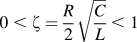 $0 \;\lt\; \zeta = {R \over 2}\sqrt {{C \over L}} \;\lt\; 1$
. In this case, the decay oscillating high-energy pulse current can be given as
 $$i\left( t \right) = {{2{U_0}\zeta } \over {R\sqrt {1 - {\zeta ^2}} }}{{\rm{e}}^{ - \zeta {\omega _n}t}}\sin \left( {\sqrt {1 - {\zeta ^2}} {\omega _n}t} \right)\quad .$$
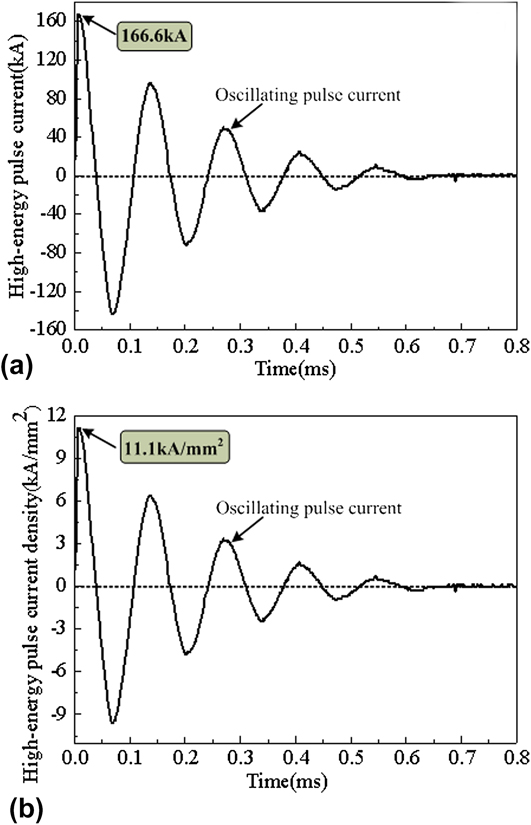
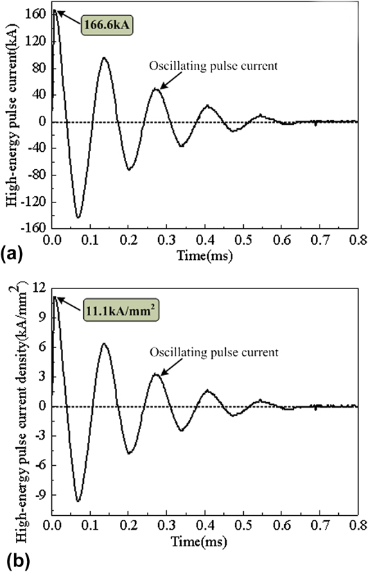
The waveform of the decay oscillating high-energy pulse current captured by the pulse current measuring module is shown in Fig. 3. Figure 3(a) shows the waveform of the decay oscillating high-energy pulse current, and it can be found from Fig. 3(a) that the largest current can reach about 166.6 kA and the pulse duration of single decay oscillating high-energy pulse current is less than 0.8 ms. Figure 3(b) shows the waveform of the decay oscillating high-energy pulse current density, and it can be found from Fig. 3(b) that the largest current density can reach about 11.1 kA/mm2. In this case, the dislocation motion can be easily activated with the help of the instantaneous higher electric energy, which results in that the shear plastic deformation can easily happen inside the specimen. In other words, the EP effect will happen during the high-energy oscillating ECP stress relief. As a result, the residual stress in the specimen can be eliminated when the specimen is exposed on the oscillating electric field. The related experimental studies of the high-energy oscillating ECP stress relief can be shown in Sec. III and IV to study the effectiveness of the high-energy oscillating ECP stress relief on the small AISI 1045 steel specimens subjected to the pulsed-laser surface irradiation.
(a) The decay oscillating high-energy pulse current; (b) the decay oscillating high-energy pulse current density.
III. EXPERIMENTAL DETAILS
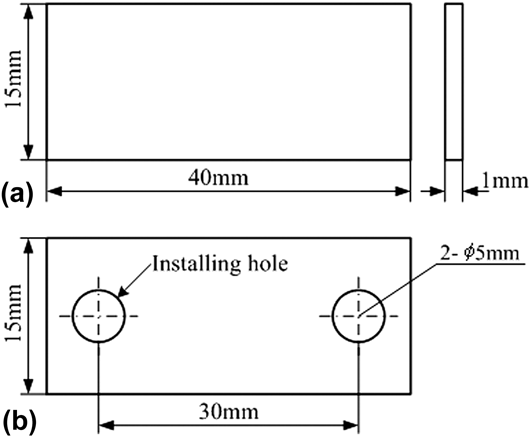
The AISI 1045 steel was used in the experimental studies, whose chemical composition is listed in Table I. To study the effectiveness of the high-energy oscillating ECP stress relief on small workpieces, a group of small AISI 1045 steel specimens were prepared from the AISI 1045 steel sheet by the fine electro-discharge wire cutting process. The dimension of a small AISI 1045 steel specimen is 40 × 15 × 1 mm as shown in Fig. 4(a). To connect the AISI 1045 steel specimen into the discharge module shown in Fig. 1, the two installing holes were reserved in the AISI 1045 steel specimen shown in Fig. 4(b). Meanwhile, the AISI 1045 steel specimens shown in Fig. 4(b) were used to conduct the subsequent experimental studies of the high-energy oscillating ECP stress relief.
Chemical composition of AISI 1045 steel used in the experimental studies (wt%).

Dimension diagram of a small AISI 1045 steel specimen (a) used in the pulse-laser surface irradiation and (b) used in the high-energy oscillating ECP stress relief.

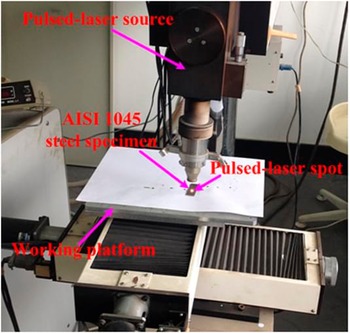
The pulsed-laser surface irradiation was used to introduce the initial residual stress in the AISI 1045 steel specimens. The experimental setup for the pulsed-laser surface irradiation can be shown in Fig. 5. The pulsed-laser surface irradiation experiments were carried out based on an Nd:YAG pulsed-laser machine, in which the small AISI 1045 steel specimens were fixed on the working platform to be treated by the high-energy pulsed-laser beam. The high-energy pulsed-laser beam was focused on the AISI 1045 steel specimen surface with the aid of an integrating mirror optic. Under this condition, the temperature in the pulsed-laser-specimen interaction area is increasing induced by the pulsed-laser surface irradiation, which results in that the larger tensile residual stress would be introduced in the AISI 1045 steel specimen owing to the phase-transformation-induced microstructure change according to our previous studies. Reference Gu, Yang, Pan and Wei22
Experimental setup for the pulsed-laser surface irradiation.

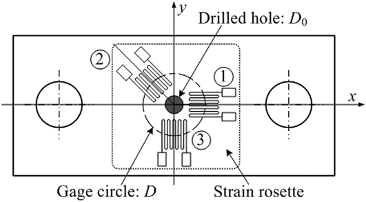
To evaluate the effect of the high-energy oscillating ECP stress relief, the hole-drilling method Reference Standard23 was used in this study. The schematic of a typical three-element clockwise rosette used for evaluating the plane residual stress in this study is shown in Fig. 6. Reference Standard23 In Fig. 6, D is the diameter of the gage circle, D 0 is the diameter of the drilled hole and the strain rosette has three groups of strain grids, in which the relieved strains in three directions can be perceived by the strain rosette. The strain grid 1 and the strain grid 3, respectively, coincide with the x-axis and the y-axis, and the angle between the strain grid 2 and the x-axis is 45° as shown in Fig. 6. During the residual stress testing process, Reference Standard23 the residual stress in the AISI 1045 steel specimen surrounding the drilled hole was partially relieved when a hole was drilled on the AISI 1045 steel surface. The corresponding relieved strain could be perceived by the strain rosette shown in Fig. 6 and then would be obtained by a strainmeter. Assuming the stress distribution along the thickness direction of the small AISI 1045 steel specimen is uniform or the stress gradient along the thickness direction is very small and can be ignored, the corresponding relieved strain can be given as Reference Standard23
 $$\varepsilon = {{1 + \nu } \over E}\bar a{{{\sigma _x} + {\sigma _y}} \over 2} + {1 \over E}\bar b{\tau _{xy}}\,\sin \,2\theta + {1 \over E}\bar b{{{\sigma _x} - {\sigma _y}} \over 2}\,\cos \,2\theta \quad ,$$
where ε is the relieved strain surrounding the drilled hole, ν is the Poisson's ratio of the materials, E is the Yong's modulus of the materials,
 $\bar a$
is the calibration constant for isotropic stresses,
 $\bar b$
is the calibration constant for shear stresses, σ
x
is the x axial residual stress, σ
y
is the y axial residual stress, τ
xy
is the shear xy-plane residual stress, and θ is the anticlockwise angle of strain grid from the x-axis. Based on Eq. (5), the x axial and y axial residual stresses can be derived based on the Standard ASTM E 837-08
Reference Standard23
 $$\left\{ \matrix{ {\sigma _x} = \left( {{E \over {2(1 \,+\, \nu )\bar a}} + {E \over {2\bar b}}} \right){\varepsilon _1} + \left( {{E \over {2(1 \,+\, \nu )\bar a}} - {E \over {2\bar b}}} \right){\varepsilon _3} \hfill \cr {\sigma _y} = \left( {{E \over {2(1 \,+\, \nu )\bar a}} - {E \over {2\bar b}}} \right){\varepsilon _1} + \left( {{E \over {2(1 \,+\, \nu )\bar a}} + {E \over {2\bar b}}} \right){\varepsilon _3} \hfill \cr} \right.\quad .$$
Schematic of attached strain rosette on the measured point of the residual stress.

Figure 6 is the schematic of measured point for the surface residual stress and an attached strain rosette. The related experimental setup for measuring the surface residual stress mainly consisted of a ZDL-II residual stress measuring setup, a YE2538 static strainmeter capable of measuring three relieved strains in three different directions and a TJ120-1.5-ϕ 1.5 three-element clockwise strain rosette. The diameter of the drilled hole and the depth of the drilled hole are 2 mm and 1 mm, respectively. According to the Standard ASTM E 837-08,
Reference Standard23
the calibration constant for isotropic stresses
 $\bar a$
and the calibration constant for shear stresses
 $\bar b$
are, respectively, selected as 0.160 and 0.470.
IV. RESULTS AND DISCUSSIONS
A. Effect of high-energy oscillating ECP on residual stress
To improve the reliability of the experimental results, the five 1# specimens and the five 2# specimens were randomly selected to evaluate the residual stresses in the specimens before and after the high-energy oscillating ECP stress relief. The 1# specimens were only treated by the pulsed-laser surface irradiation to evaluate the initial residual stresses in the specimens. The 2# specimens were randomly selected to be treated by the high-energy oscillating ECP stress relief. The mainly process parameters of the high-energy oscillating ECP stress relief consist of the largest pulse current with the value of about 166.6 kA, the largest pulse current density with the value of about 11.1 kA/mm2, and the pulse duration of single decay oscillating high-energy pulse current with the value of less than 0.8 ms.
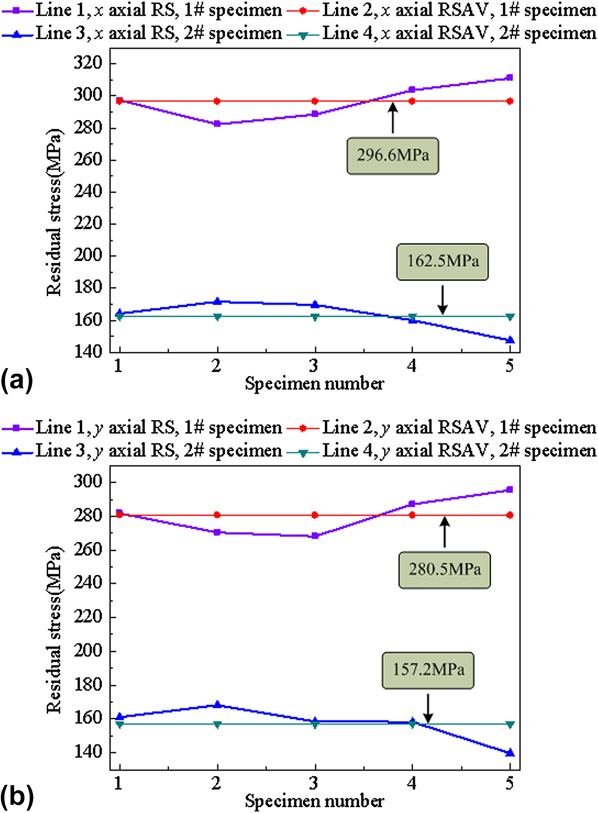
Figure 7 shows the x axial and y axial residual stresses of the five 1# specimens and the five 2# specimens. It can be found from Fig. 7 that the larger x axial and y axial tensile residual stresses are induced by the pulsed-laser surface irradiation. Meanwhile, the residual stress in the workpiece induced by the welding process is the tensile residual stress as well. Under this condition, the residual stress induced by the welding process can be simulated by the pulsed-laser surface irradiation. Figure 7(a) shows the x axial residual stresses in the specimens before and after the high-energy oscillating ECP stress relief. It can be found from Fig. 7(a) that the x axial residual stresses in the specimens can be obviously eliminated with the help of the high-energy oscillating current pulse. Figure 7(b) shows the y axial residual stresses of the specimens before and after the high-energy oscillating ECP stress relief. It can be seen from Fig. 7(b) that the y axial residual stresses of the specimens can be obviously eliminated with the help of the high-energy oscillating current pulse as well.
Residual stress evaluation results of (a) x axial residual stress and (b) y axial residual stress (RS denotes residual stress; RSAV denotes residual stress average value; 1# specimen denotes the specimen is only treated by the pulsed-laser surface irradiation; 2# specimen denotes the specimen has been treated by the high-energy oscillating ECP stress relief).
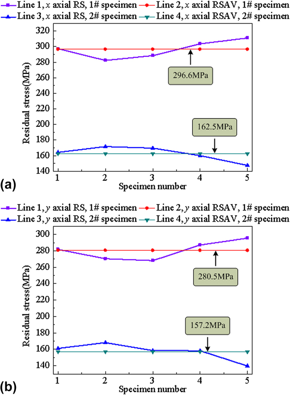
In Fig. 7(a), it can be easily seen that the average values of the x axial residual stresses before and after the high-energy oscillating ECP stress relief are 296.6 MPa and 162.5 MPa, respectively. The average relieving value of the x axial residual stresses is 134.1 MPa, and the x axial residual stress relieving rate is 45.21%. It can be easily seen from Fig. 7(b) that the average values of the y axial residual stresses before and after the high-energy oscillating ECP stress relief are 280.5 MPa and 157.2 MPa, respectively. The average relieving value of the y axial residual stresses is 123.3 MPa, and the y axial residual stress relieving rate is 43.96%. As shown in Fig. 3, the high-energy ECP can be generated and imposed into the AISI 1045 steel specimens, which is beneficial to activate the dislocation motion. Under this condition, the shear plastic deformation will easily occur inside the specimens. As a result, the larger tensile residual stresses induced by the pulsed-laser surface irradiation have been obviously eliminated by the high-energy oscillating ECP stress relief as shown in Fig. 7.
B. Effect of high-energy oscillating ECP on temperature
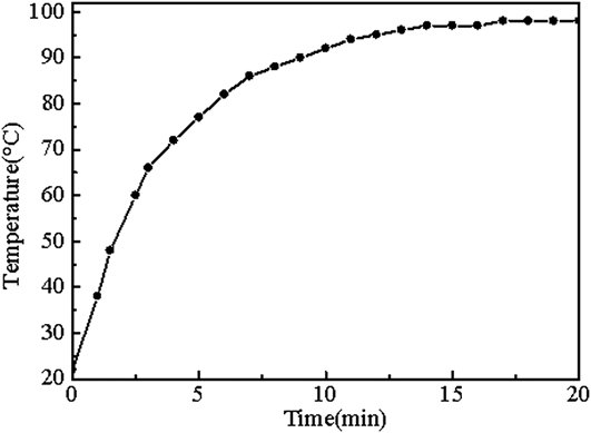
The evolution rule of the temperature field on the AISI 1045 steel specimen surface during the high-energy oscillating ECP stress relief was studied in this study. The temperature variation curve on the AISI 1045 steel surface was captured and is shown in Fig. 8. It can be found that the largest temperature can reach about 100 °C, which is beneficial to activate the dislocation motion inside the specimen. From the viewpoint of the dislocation motion, it can be concluded that the shear resistance for the dislocation motion under this condition can be reduced owing to the temperature effect induced by the high-energy oscillating ECP. In other words, the metal softening phenomenon will happen when the electric energy is imposed into the specimen. According to the studies, Reference Li, Yu and Liu16,Reference Li and Yu17,Reference Kim, Vinh, Yu, Hong, Lee, Kim, Han and Roth20 it can be found that the electric field has been proved to have the capability to soften the metals. The metal electric softening effect induced by the high-energy oscillating ECP stress relief implies that the electric energy can be effectively absorbed by the microdefects, e.g., the dislocation. Under this condition, the dislocation motion along the slip plane can be improved with the help of the electric field. As a result, the EP deformation process will easily happen inside the specimen, as expected, the residual stress in the specimen can be eliminated with the aid of the electric field. The EP model based on the thermal activation theory was developed to reveal the underlying mechanism of the high-energy oscillating ECP stress relief as shown in Sec. IV. C.
Temperature measuring results of the AISI 1045 steel specimen treated by the high-energy oscillating ECP stress relief.

C. EP model based on the thermal activation theory
To reveal the underlying mechanism of the high-energy oscillating ECP stress relief, the EP model was proposed based on the thermal activation theory. According to the studies presented by Wang et al.,
Reference Wang, He, Wang and Guo24
it can be found that the microstructure of the quenched 40Cr steel will not be changed before and after the action of electropulsing, which implies that the residual stress relieving mechanism of the high-energy oscillating ECP stress relief is not related to the microstructure. The residual stress relieving mechanism of the high-energy oscillating ECP stress relief is strongly related to the plasticity deformation.
Reference Wang, He, Wang and Guo24
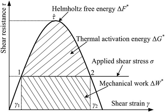
And the dislocation motion along the slip plane is the main way to produce the plasticity deformation. So that is why the EP framework was developed based on the thermal activation theory to reveal the mechanism of the high-energy oscillating ECP stress relief. Figure 9 shows the schematic of the shear resistance τ as the function of the shear strain γ according to the studies.
Reference Argon25
From the position 1 to the position 2, the total activation energy of the dislocation motion called the Helmholtz free energy
 $\Delta {F^*}$
can be given as the following equation:
Reference Argon25
 $$\Delta {F^*} = \Delta {G^*} + \Delta {W^*}\quad ,$$
where
 $\Delta {G^*}$
is the Gibbs free energy called as the thermal activation energy and the
 $\Delta {W^*}$
is the mechanical work. Assuming the activation volume is the unit volume, the Gibbs free energy
 $\Delta {G^*}$
can be given as
Reference Argon25
 $$\Delta {G^ * } = \int_{{\gamma _1}}^{{\gamma _2}} {\left[ {\tau \left( \gamma \right) - \sigma } \right]} \,{\rm{d}}\gamma \quad ,$$
where
 $\tau \left( \gamma \right)$
is the shear resistance and σ is the applied shear stress along the slip plane. The mechanical work can be expressed as
Reference Argon25
 $$\Delta {W^ * } = \int_{{\gamma _1}}^{{\gamma _2}} {\sigma \,{\rm{d}}\gamma } = \sigma \left( {{\gamma _2} - {\gamma _1}} \right)\quad .$$
Schematic of the shear resistance τ as the function of the shear strain γ.

It can be concluded that the activation energy for the dislocation motion mainly consisted of the Gibbs free energy and the mechanical work. According to the studies by Kocks et al., Reference Kocks, Argon and Ashby26,Reference Kocks and Miller27 the shear plastic strain rate owing to the thermally activated dislocation motion along the slip plane is generally expressed as
 $${\dot \gamma ^{\rm{p}}} = {\dot \gamma _0}\exp \left( {{{ - \Delta G} \over {kT}}} \right)\quad ,$$
where
 ${\dot \gamma ^{\rm{p}}}$
is the shear plastic strain rate,
 ${\dot \gamma _0}$
is the pre-exponential factor and can be regarded as a numerical constant,
 $\Delta G$
is the Gibbs free energy for overcoming an obstacle, k is the Boltzmann constant, and T is the absolute temperature. The maximum shear resistance for the dislocation motion called as mechanical threshold can be given as
Reference Kocks, Argon and Ashby26–Reference Kocks28
 $$\hat \tau = {\tau _0} + aGb\sqrt {{\rho _{\rm{d}}}} \quad ,$$
where
 ${\rho _{\rm{d}}}$
denotes the dislocation density, τ0 is the friction stress generated by the crystal lattice, a is a numerical constant,
 $G$
is the shear modulus, and
 $b$
is the magnitude of the Burgers vector. Based on Eq. (11), it can be found that the shear resistance for the dislocation motion is strongly related to the dislocation density. The dislocation density evolution governing equation can be expressed as
Reference Kocks28–Reference Estrin and Mecking30
 $${{{\rm{d}}{\rho _{\rm{d}}}} \over {{\rm{d}}{\gamma ^{\rm{p}}}}} = {k_1}\sqrt {{\rho _{\rm{d}}}} - {k_2}{\rho _{\rm{d}}}\quad ,$$
where k 1 represents the dislocation storage coefficient representing the dislocation accumulation process and can be regarded as a numerical constant; k 2 represents the dynamic recovery coefficient representing the dislocation annihilation process and is affected by the plastic strain state and the temperature. As shown in Fig. 8, the temperature on the AISI 1045 steel specimen surface treated by the high-energy oscillating ECP stress relief can reach about 100 °C, which implies that the dislocation annihilation process can be improved with the help of the electric field. Under this condition, the dislocation density evolution governing equation with the aid of the electric field can be further given as
 $${{{\rm{d}}{\rho _{\rm{d}}}} \over {{\rm{d}}{\gamma ^{\rm{p}}}}} = {k_1}\sqrt {{\rho _{\rm{d}}}} - {k_2}\left( {1 + \eta } \right){\rho _{\rm{d}}}\quad ,$$
where the nondimensional parameter η represents the change ratio of k 2 owing to the exposure in the oscillating electric field. η relates to the additional dislocation annihilation process induced by the high-energy oscillating ECP. Considering the metal softening phenomenon obtained by the related scholars, Reference Li, Yu and Liu16,Reference Li and Yu17,Reference Kim, Vinh, Yu, Hong, Lee, Kim, Han and Roth20 we believe that the metal softening phenomenon can be attributed to the thermal effect. Under this condition, the dislocation annihilation process has a dominant position compared with the dislocation accumulation process, which results in that the dislocation density decreases with the help of the electric field. So the shear resistance τc for the dislocation motion owing to the metal softening effect shown in Fig. 9 can be given as
 $${\tau _{\rm{c}}} = \delta \hat \tau = \delta \left( {{\tau _0} + \alpha Gb\sqrt {{\rho _{\rm{d}}}} } \right)\quad ,$$
where δ represents the electric softening coefficient related to the local temperature. The forming mechanism of the metal softening effect can be revealed based on Eqs. (7)–(14). The significant temperature increasing can be induced as shown in Fig. 8 since the microdefects inside the materials, e.g., the dislocations, can effectively absorb the electrical energy. Under this condition, the thermal activation energy for the dislocation motion can be increased. As a result, the driving stress forcing the dislocation motion can be reduced as shown in Fig. 9, that is to say, the shear resistance for the dislocation motion decreases. The coefficient δ in Eq. (14) also can be called as the electric energy absorbing coefficient by the microdefects inside the materials, e.g., the dislocations, which directly affect the metal softening effect induced by the electric field.
In addition to the metal softening effect produced by the external electric field, the driving stress forcing the dislocation motion can be induced by the external electric field as well. The driving stress forcing the dislocation motion mainly includes the instantaneous heat pressure stress induced by the nonuniform Joule heat effect Reference Wang, He, Wang and Guo24,Reference Zhao, Ma, Guo, Ma, Yang and Song31 and the electron-wind-force induced by the drift electron. Reference Zheng, He and Shi21,Reference Roshchupkin and Bataronov32 Under this condition, the driving stress for the dislocation motion can be given as
 $${\sigma _{\rm{d}}} = {\sigma _{\rm{t}}} + {\sigma _{\rm{e}}}\quad ,$$
where σd is the applied shear stress forcing the dislocation motion along the slip plane shown in Fig. 9, σt is the instantaneous heat pressure stress, and σe is the electron-wind-force. The instantaneous heat pressure stress σt can be given as Reference Wang, He, Wang and Guo24,Reference Zhao, Ma, Guo, Ma, Yang and Song31
 $${\sigma _{\rm{t}}} = {{E\alpha {\rho _{\rm{e}}}\lambda } \over {{\rho _{\rm{m}}}c}}{J^2}\quad ,$$
where E is the elasticity modulus, α is the coefficient of thermal expansion, ρe is the electrical resistivity, λ is the pulse duration, ρm is the density of the materials, c is the specific heat capacity, and the J is the pulse current density with the value of 11.1 kA/mm2. It can be found from Eq. (16) that the instantaneous heat pressure stress is proportional to the square of pulse current density, which implies that the high-energy oscillating ECP imposed into the specimen can easily force the dislocation motion and increasing the pulse current density can obviously improve the instantaneous heat pressure stress. Under this condition, it can be concluded that the residual stress relieving effect is strongly related to the pulse current density based on Eq. (16). This is why the high-energy pulse current density has been used in this study. The electron-wind-force
 ${\sigma _e}$
can be given as
Reference Zheng, He and Shi21,Reference Roshchupkin and Bataronov32
 $${\sigma _{\rm{e}}} = {1 \over 3}nmb{v_{\rm{F}}}\left( {{v_{\rm{e}}} - {v_{\rm{d}}}} \right) = {{mb{v_{\rm{F}}}} \over {3e}}J\quad ,$$
where n is the electron density, m is the effective mass of the electron, b is the magnitude of the Burgers vector, v F represents the Fermi velocity, v e represents the velocity of the drift electron, v d represents the velocity of the dislocation motion, e represents the elementary charge and belongs to a numerical constant. It can be found from Eq. (17) that the electron-wind-force is proportional to the pulse current density, which implies that the dislocation can be easily activated by the high-energy oscillating pulse current. In this case, the residual stress relieving effect can be improved by increasing the pulse current density as well based on Eq. (17). So the criteria of residual stress relieving induced by the dynamic stress effect and the electric softening effect can be obtained as
 $${{E\alpha {\rho _{\rm{e}}}\lambda } \over {{\rho _{\rm{m}}}c}}{J^2} + {{mb{v_{\rm{F}}}} \over {3e}}J > \delta \hat \tau \quad .$$
The criteria implies that the mechanism of the high-energy oscillating ECP stress relief can be attributed to the electric softening effect induced by the local increasing temperature and the dynamic stress effect consisted of the instantaneous heat pressure stress and the electron-wind-force. Under this condition, the larger tensile residual stress in the AISI 1045 steel specimen induced by pulsed-laser surface irradiation can be eliminated by the high-energy oscillating ECP stress relief. Eqs. (7)–(18) provide a constitutive model governing the relationship between the pulse current density J and the shear plastic strain γ. The constitutive model develops an EP framework to account the EP induced by the oscillating electric field and the underlying mechanism of the high-energy oscillating ECP stress relief can be attributed to the electric softening effect and the dynamic stress effect.
V. CONCLUSIONS
The high-energy oscillating ECP stress relief was introduced to relieve the residual stresses in the small AISI 1045 steel specimens treated by the pulsed-laser surface irradiation based on the Nd:YAG pulsed-laser machine. The high-energy oscillating ECP stress relief experiments were conducted to study the effectiveness of the high-energy oscillating ECP technology. In addition, the EP framework was developed based on the thermal activation theory to reveal the mechanism of the high-energy oscillating ECP stress relief. The main conclusions can be drawn as follows:
-
(1) The main parameters of the high-energy oscillating ECP stress relief consist of the largest current with the value of 166.6 kA, the pulse duration of single decay oscillating high-energy pulse current with the value of less than 0.8 ms, and the largest current density with the value of 11.1 kA/mm2.
-
(2) The average values of the x axial residual stresses before and after the high-energy oscillating ECP stress relief are 296.6 MPa and 162.5 MPa, respectively. Meanwhile, the average values of the y axial residual stresses before and after the high-energy oscillating ECP stress relief are 280.5 MPa and 157.2 MPa, respectively. The x axial residual stress relieving rate is 45.21% and the y axial residual stress relieving rate is 43.96%. The high-energy oscillating ECP stress relief has good effects on eliminating the residual stress.
-
(3) The EP framework is developed based on the thermal activation theory. It can be concluded that the mechanism of the high-energy oscillating ECP stress relief can be attributed to the electric softening effect and the dynamic stress effect. The unified EP model can accurately account the electric softening effect and the dynamic stress effect in the AISI 1045 steel.
The unified EP model is developed based on the thermal activation theory and can accurately account the electric softening effect and the dynamic stress effect of the high-energy oscillating ECP stress relief. The findings confirm that the high-energy oscillating ECP stress relief is promising to eliminate the local residual stress in the small workpieces and provide a basis to understand the underlying mechanism of the high-energy oscillating ECP stress relief.
ACKNOWLEDGMENT
This research is sponsored by the high-tech research and development program of China (No. 2013A2041106).