I. INTRODUCTION
Generally, biomechanical incompatibility between bone and surgical implants leads to bone resorption around implants, causing the “so-called” stress shielding effect. It is well known that titanium (Ti)-based biomaterials have lower elastic moduli compared with the currently applied metallic biomaterials (e.g., cobalt chromium alloys and 316L stainless steel) and, hence, are able to reduce the stress shielding effects, leading to increased longevity of the implants in human body. Reference Geetha, Singh, Asokamani and Gogia1 Ti-based materials not only show low Young's modulus but also exhibit high strength, low density, good corrosion resistance, and high biocompatibility. That is why they have received a great deal of attention as potential candidate materials in biomedical applications. On the other hand, Ti and Ti-based alloys exhibit relatively poor wear resistance and low hardness which may affect their application areas. Reference Qin, Geng and Ni2 Addition of ceramic reinforcement to Ti alloys can extend their attractiveness in biomedical applications where high specific strength combined with enhanced wear resistance is required. Several strengthening compounds are used to reinforce Ti alloys and these include TiN, Reference Cui, Zhu, Man and Yang3 TiC, Reference Lu, Zhang, Zhang, Wu, Sakata and Mori4 SiC, Reference Fromentin, Debray, Le Petitcorps, Martin and Quenisset5 B4C, Reference Jeong, Kim, Hyun and Lee6 and TiB. Reference Chandran, Panda and Sahay7 Thermodynamic and chemical instabilities of reinforcement phase in Ti matrix need to be considered as this may lead to the formation of brittle reaction zones. Reference Gorsse, Petitcorps, Matar and Rebillat8,Reference Gofrey, Goodwin and Ward-Close9 It has been reported that titanium monoboride (TiB) is a suitable discontinuous reinforcement which has thermodynamic and mechanical stability as well as high potential for biomedical applications. Reference Gorsse, Petitcorps, Matar and Rebillat8,Reference Wei, Zhang, Wang, Shen, Cai, Lee and Wang10,Reference Morsi and Patel11 TiB particles can be produced by an in situ reaction between Ti and titanium diboride (TiB2) which leads to the formation of good interfacial bonds between Ti matrix and TiB reinforcements. The great advantages of in situ reactions for producing in situ metal matrix composites compared to ex situ methods have been reported in Ref. Reference Tjong and Ma12.
Ti-based biomaterials are produced using common technologies, particularly powder metallurgy (PM), Reference Bolzoni, Esteban, Ruiz-Navas and Gordo13 casting, Reference Zhu, Kamiya, Yamada, Watazu, Shi and Naganuma14 and, recently, layer additive manufacturing technique. Reference Campoli, Borleffs, Yavari, Wauthle, Weinans and Zadpoor15 Generally, competition between manufacturing processes for producing samples is a function of required geometrical complexity, quality, and quantity. As shown in Ref. Reference Levy, Schindel and Kruth16, layer manufacturing techniques exhibit higher capacity to produce complex shapes compared with casting and PM methods. Selective laser melting (SLM), as a newly developed layer manufacturing technique, allows a direct digitally-enabled fabrication of near net-shape structures by selectively melting/consolidating successive powder layers under a protective atmosphere, using a computer-controlled laser beam. Compared with conventional methods, SLM provides a broader range of advantages, namely rapid production of objects with complex geometry, high material utilization rate, and direct production based on CAD models which eliminates expensive post-processing. Reference Attar, Calin, Zhang, Scudino and Eckert17–Reference Attar, Bönisch, Calin, Zhang, Scudino and Eckert20
SLM is basically a full melting/solidification process, which can even melt high-melting point ceramics during its fabrication. Reference Gu, Hagedorn, Meiners, Wissenbach and Poprawe21 In addition, unlike conventional manufacturing techniques, the heating/cooling rate in the SLM process is very high (103–108 K/s) Reference Attar, Calin, Zhang, Scudino and Eckert17 which generally causes refinement of the microstructure and, consequently, improvement of the mechanical properties. However, such a high cooling rate in the SLM process may lead to minor brittleness in the manufactured material. The SLM process involves different processing strategies as compared with the PM and casting processes. The effect of SLM processing on the microstructural characteristics and mechanical properties of Al-based alloys and Ti-based alloys has been studied. Reference Prashanth, Scudino, Klauss, Surreddi, Löber, Wang, Chaubey, Kühn and Eckert22–Reference Wang, Zhang, Fang and Sercombe24 On the other hand, there is only limited number of investigations in relation to SLM processing of Ti-based composites. Reference Attar, Bönisch, Calin, Zhang, Scudino and Eckert20,Reference Gu, Hagedorn, Meiners, Wissenbach and Poprawe21
This study discusses and compares the microstructures and mechanical properties of in situ Ti–TiB composites produced by the three different methods. In the present work, Ti–TiB composites were fabricated from milled Ti–5 wt.% TiB2 powders using SLM, casting, and PM techniques. The reaction temperature between starting powders, resultant microstructures, and phase constitutions were studied. Compressive strength, microhardness, and Young's modulus of the samples were investigated as the objective of this work. This study shows that all processing routes yield Ti–TiB composites that have high potential to be further developed for medical applications.
II. EXPERIMENTAL
A. Starting powders and manufacturing techniques
In the present study, commercially pure Ti (CP-Ti) powder (99.7% purity, d 50 = 48.69 µm) and TiB2 powder (98.9% purity, d 50 = 3.5–6 µm) were used. The Ti–5 wt.% TiB2 powder system was mixed under protective atmosphere and poured into ball-mill vials. The milling process was carried out in a Retsch planetary ball mill (Retsch, Haan, Germany) for 2 h at a constant rotation speed of 200 rpm using vials and C15 carbon steel balls. The ball-to-powder weight ratio was set to 5:1 and the ball diameter was 10 mm. The milled Ti–5 wt.% TiB2 powder was used as the starting materials for PM, casting, and SLM.
To produce composite samples by the PM technique, the Ti–5 wt.% TiB2 powder was uniaxially pressed at three different pressures of 450, 580, and 700 MPa for 1 h at room temperature to form green compacts. Subsequently, the green compacts were sealed in argon filled quartz tubes and sintered at 1100 °C (40 °C/min heating rate) for 3 h and finally water quenched.
Composite cast ingots were prepared by arc-melting of the compacted Ti–5 wt.% TiB2 powder. The ingots were subsequently remelted three times for homogenization. From these ingots, cast bulk cylinders with 4 mm diameter were obtained using a cold crucible casting device. A MTT SLM 250 HL machine (MTT Technologies, Lubeck, Germany) containing a 400 W Yb:YAG fiber laser with an 80 µm spot size was used to produce cylindrical parts with 4 mm diameter under protective high-purity argon atmosphere. Samples were produced with an optimized set of manufacturing parameters, i.e., a laser power of 180 W, a laser scanning speed of 150 mm/s, a 100 µm hatching distance, and a 100 µm layer thickness. Layers were scanned using a continuous laser mode according to a zigzag pattern, which was alternated by 90° between each layer.
B. Microstructural characterization
Differential scanning calorimetry (DSC) was carried out using a NETZSCH DSC 404 (NETZSCH, Selb, Germany) device to study the chemical reaction temperature between the starting powders. To this end, both Ti–5 wt.% TiB2 and CP-Ti powders (as a reference) were heated from room temperature to 1200 °C and then cooled to room temperature at a controlled heating/cooling rate of 20 °C/min. To determine the completion temperature of the chemical reaction, x-ray diffraction (XRD) was run using an X’Pert PRO MPD (PANalytical, EA Almelo, The Netherlands) device with Co Kα radiation (λ = 0.1790 nm) at 40 kV and 40 mA in a continuous scan mode over a wide range of 2θ = 30–100° for Ti–5 wt.% TiB2 powders heated (using the same DSC device) to different temperatures of 700, 800, 900, 1000, and 1100 °C. Moreover, phase identifications of the samples produced by casting, SLM, and PM methods were carried out with XRD using the same device and conditions.
The morphologies of CP-Ti, TiB2, and the milled Ti–5 wt.% TiB2 powders as well as of the samples fabricated by PM were studied using a Zeiss 1555 scanning electron microscope (SEM, Carl Zeiss AG, Oberkochen, Germany). The density of all samples produced in three different ways was measured using Archimedes' method. X-ray computed tomography (CT) of 4 µm resolution was used to study the internal distribution of porosities in samples processed by PM. To study the microstructures and morphologies, cast and SLM-processed samples were sectioned in the transverse cross-sectional of the cast rod and the cross-sectional (X-Y, i.e., the laser melting layer plane) of the SLM-produced samples, then ground, and polished using standard metallographic procedures. Afterward, samples were etched using a solution containing 10% HF, 5% HNO3, and 85% distilled water (volume fractions) and investigated using the same SEM device. Specimens for transmission electron microscopy (TEM) were prepared by cutting thin lamellae normal to the polished sample surface with a beam of focused Ga ions. The specimens obtained were investigated in a Tecnai T20 transmission electron microscope (FEI, Oregon) operated at 200 kV.
C. Mechanical properties tests
Compressive tests were conducted using an Instron 5869 machine (Instron, MA) at a controlled cross-head speed of 0.001 mm/s in accordance with the standard DIN 50106. Vickers microhardness was performed on polished samples using a HMV Shimadzu Microhardness Tester (Shimadzu, Kyoto, Japan) with 50 g load and 10 s dwelling time. An average of 10 indents was taken for each measurement.
III. RESULTS AND DISCUSSIONS
A. Morphological characterization and differential scanning calorimetry study
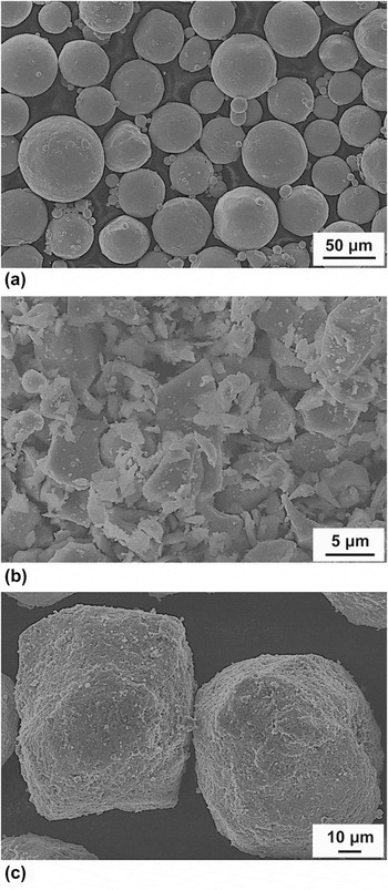
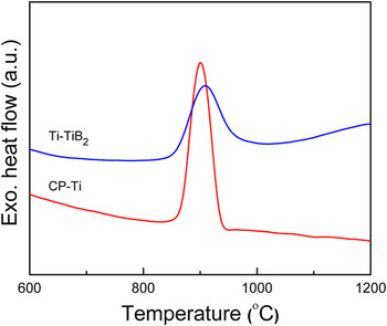
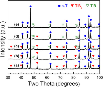
Figure 1 depicts the morphologies of the as-received CP-Ti, TiB2, and as-milled Ti–5 wt.% TiB2 powders. As can be seen in Figs. 1(a) and 1(b), CP-Ti powders exhibit a spherical morphology whilst TiB2 particles have an irregular shape. The milled Ti–TiB2 powders have a nearly spherical shape [Fig. 1(c)] which is suitable for SLM processing because of its high flowability. Also, TiB2 particles are connected homogenously to the Ti particles. Figure 2 shows the DSC results of the CP-Ti and the milled Ti–TiB2 powders. As seen from the DSC curves, only peaks relating to β transition temperature are evident (around 900 °C) at which an allotropic phase transformation between α and β phase occurs. However, the β transus peak in the Ti–TiB2 powder showed a lower height of intensity compared with that for the CP-Ti powder. It has been reported that the reaction between Ti and TiB2 starts approximately at 800 °C Reference Feng, Jia and Zhou25 and that transformation is exothermic. Reference Galvan, Ocelik, Pei, Kooi, De Hosson and Ramous26 It appears that the heat flow signals relating to the β transus and the chemical reaction originating from Ti and TiB2 powders overlapped with each other and hence reduced the intensity of peak in Ti–TiB2 powder. The XRD patterns of the milled Ti–TiB2 powders heated up to 1100 °C are shown in Fig. 3. As illustrated, diffraction peaks of Ti–TiB2 powder heated to 700 °C corresponded only to hexagonal close-packed (hcp) titanium or hexagonal TiB2 but no reflections of TiB were observed. On increasing the temperature up to 1100 °C, peaks corresponding to orthorhombic TiB appeared and peaks of TiB2 reduced and finally disappeared at 1100 °C. This indicates that the reaction between Ti and TiB2 occurs between 800 and 1100 °C. Based on this observation, the temperature of 1100 °C was selected for the sintering of compacted composite samples to allow for completion of the in situ reaction between Ti and TiB2.
Particle shape morphology of the starting powders: (a) CP-Ti, (b) TiB2, and (c) the homogenously mixed Ti–TiB2.

DSC heating curves for Ti–TiB2 and CP-Ti powders.

XRD patterns of the Ti–TiB2 powder heated to different temperatures of (a) 700 °C, (b) 800 °C, (c) 900 °C, (d) 1000 °C, and (e) 1100 °C.

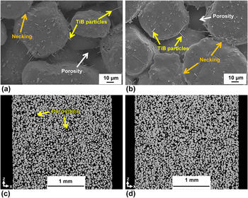
Figures 4(a) and 4(b) show the microstructures of PM-produced Ti–TiB compacts pressurized by 450 and 700 MPa after sintering. It can be observed that necking between particles has occurred. However, as expected, necking of the powders for less pressurized samples was quite smaller [Fig. 4(a)]. Moreover, TiB needles protruding in radial direction from the Ti-particles were visible and, as mentioned, they were produced due to the reaction between Ti and TiB2 during sintering. Incomplete joining of the particles led to the formation of porosities in all compacted samples. Formation of porous specimens can be related to the fact that the starting milled powders had a nearly spherical shape and compacting forces were not sufficient to deform particles and consequently reduce spaces among them. Moreover, unlike casting and SLM processes, neither full melting nor full sintering happens among powders during sintering in PM process and, instead, partial sintering occurred among them, causing incomplete connection of the particles to each other. Micro-CT images of these samples from longitudinal sections are shown in Figs. 4(c) and 4(d). The porosity levels for samples compacted with pressures of 450, 580, and 700 MPa were measured to be around 36%, 29%, and 25%, respectively. As evidenced, the samples exhibit an interconnected porosity, which is one of the most essential requirements for tissue ingrowth. Reference Heinl, Müller, Körner, Singer and Müller27 It is well known that porous materials are suitable for surgical bone-replacing implants as the connective network configuration of pores may benefit osteogenesis and provide a firm bonding between the human bone and the implant. Reference Kobashi, Kuze and Kanetake28,Reference Chen, Feng, Zhu, Weng, Wang and Lu29
SEM microstructures of (a) 36% and (b) 25% porous PM-processed Ti–TiB composites; CT longitudinal images of (c) 36% and (d) 25% porous PM-processed Ti–TiB composites.

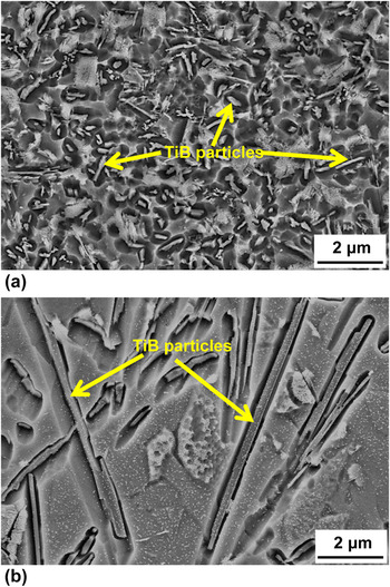
Figure 5 displays the SEM microstructures of almost fully dense (99.5%) SLM-processed and as-cast Ti–TiB composites. It is observed that the TiB particles were distributed rather homogenously within the whole Ti matrix and exhibit a needle-shape morphology. It is apparent that the TiB particles are much coarser in cast composite samples than in SLM-processed ones. This may be attributed to the differences in temporal duration of the casting and the SLM processes. The heating/cooling rate in the SLM process is very high (103–108 K/s), Reference Gu, Hagedorn, Meiners, Meng, Batista, Wissenbach and Poprawe30 and thus, compared with the casting process, the time available for growth of TiB particles during SLM is much shorter.
SEM microstructures of (a) SLM-processed and (b) cast Ti–TiB composites.

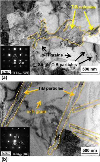
Both casting and SLM involve full melting and subsequent solidification of the raw materials, but give rise to distinctively different microstructures. Thus, the influence of both processing techniques on the solidification microstructures was further examined by TEM. Bright-field TEM imaging of the SLM-processed and cast Ti–TiB composite materials revealed two additional microstructural differences, as demonstrated in Fig. 6. First, in the SLM material, the typical grain size of α-Ti is finer by a factor of 0.5 or so compared to the cast state. Second, in the SLM material, a large fraction of the monoboride particles are closely stacked in a parallel manner to form colonies, as those depicted in Fig. 6(a). The boride particles in these colonies exhibit typical thicknesses ranging from 25 to 50 nm. Besides boride colonies, single boride particles included by the α-Ti matrix can be found in the SLM material. Most of them were thin (typical thickness of 20–50 nm) and short (typical length of 100–500 nm), however, also a few thicker (typical thickness of 100–200 nm) and longer ones (typical length of 0.5–3 µm) were observed. By contrast, in cast samples, only thick and long boride particles were observed and stacks of parallel boride needles were absent, as shown in Fig. 6(b). It appears that, in current study and our previous work, Reference Attar, Bönisch, Calin, Zhang, Scudino and Eckert20 average sizes of Ti grains and TiB particles in SLM-processed Ti–TiB samples are smaller than those of cast composite parts, owing to much higher cooling rate during SLM processing compared with that in casting technology. Reference Attar, Calin, Zhang, Scudino and Eckert17,Reference Zhang, Calin, Paturaud and Eckert31 The presence of TiB in the SLM and cast materials was confirmed by TEM analysis. In both materials, electron diffraction patterns of the boride particles, such as those shown in the insets in Fig. 6, evidenced that these particles are monoborides. All boride particles investigated were identified as monoborides. This observation suggests that the reaction from Ti and TiB2 to Ti–TiB was completed both in the as-cast and even in the SLM-processed material, despite the very short times available for melting and solidification during SLM.
TEM images showing the microstructures of the (a) SLM-processed and (b) cast composites. The insets show typical electron diffraction patterns of the TiB particles, which can be indexed with the monoboride (TiB) B27 phase.

Previous studies showed that TiB is produced in the form of whiskers inside Ti matrix and their growth direction is parallel to [010]B27 direction. Reference Sahay, Ravichandran, Atri, Chen and Rubin32–Reference Lu, Xiao, Geng, Qin and Zhang35 In other words, TiB whisker axis was found to be parallel to the [010] axis of the B27 cell. Reference Lu, Zhang, Zhang, Wu, Sakata and Mori4,Reference Wei, Zhang, Wang, Shen, Cai, Lee and Wang10 The reason for this type of morphology is that boron atoms have zigzag and continuous arrangement and also B–B bonds are strong in [010]B27 direction, and hence, growth rates can be higher in this direction compared with the [100]B27, [101]B27, and [001]B27 directions. Reference Sahay, Ravichandran, Atri, Chen and Rubin32 Therefore, the higher growth in the [010]B27 direction leads to development of needle-shape/rod-shape morphology in a TiB particle.
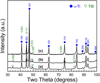
The XRD profiles of Ti–TiB composites produced by PM, casting, and SLM methods are shown in Fig. 7. As illustrated, only peaks corresponding to Ti and/or TiB are present in all the patterns. This indicates that Ti and TiB2 reacted to form a Ti–TiB composite during processing by SLM, casting, and PM techniques. Based on the standard thermodynamic data about Ti compounds, Reference Panda and Chandran36,Reference Panda and Chandran37 Ti can react with TiB2 or B to produce TiB, as the free-energy (ΔG) of these reactions is negative despite the fact that ΔG of TiB2 formation from Ti and B is more negative. But it has been reported that when the average concentration of B in the reaction zone is less than 18–18.5 wt.%, TiB particles would be formed due to a reaction between Ti and TiB2. Reference Panda and Chandran37 The average weight percent of boron in both the starting Ti–TiB2 powder and the produced samples was measured by chemical analysis (ICP-OES technique) to be 1.50 wt.%. Accordingly, the volume fraction of TiB reinforcements was calculated to be around 8.35 wt.%.
XRD patterns of (a) cast, (b) PM, and (c) SLM-processed Ti–TiB composites.

B. Mechanical properties
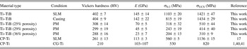
Table I compares the Vickers microhardness of the Ti–TiB composite samples manufactured by different techniques with that of CP-Ti. It is apparent that all composite samples produced by any of the three processing routes used in the present study showed greater microhardness than CP-Ti. This increase in hardness can be explained by the hardening effect induced by the reinforcing TiB particles. PM-processed samples show slightly different microhardness and this may be attributed to the different level of work hardening and porosities induced by various pressures. In other words, 700 MPa pressure caused slightly higher work hardening effect on the powders than 450 MPa. In addition, both SLM-processed and cast samples exhibit comparable microhardness and their hardness values were greater than all samples produced by PM technique and also CP-Ti. It has been reported that enhancement of hardness may improve wear resistance of implants. Reference Calin, Gebert, Ghinea, Gostin, Abdi, Mickel and Eckert38 Consequently, an improvement of the wear resistance may prevent implants loosening and enhance their longevity in human body. Reference Geetha, Singh, Asokamani and Gogia1
Microhardness and mechanical properties obtained by compression tests of Ti–TiB composites and CP-Ti manufactured by different processing methods. E is Young's modulus; σ0.2 denotes compressive yield strength; σUCS indicates ultimate compressive strength; CG-Ti denotes coarse-grained Ti.

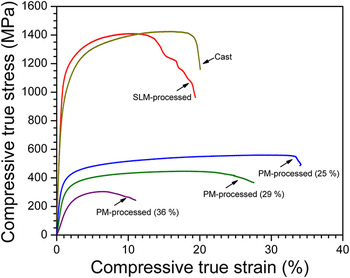
The compressive true stress–strain curves of the SLM-processed, cast, and three porous Ti–TiB composite samples are depicted in Fig. 8. In SLM-processed and cast samples, a first linear regime was observed and then stress increased nonlinearly up to a maximum, followed by a drop in stress due to commencement of cracks until the final fracture. Both the SLM-processed and cast samples showed a nearly similar behavior of compressive properties especially in terms of ultimate strength and maximum fracture strain. However, SLM-processed samples showed higher yield stresses compared with that of cast samples (Table I). The higher yield stress in the SLM-processed Ti–TiB composite can be attributed to finer Ti grains and TiB particles resulted from high cooling rate during SLM. According to the well-known Hall–Petch relationship, grain refinement of Ti leads to the improvement of yielding strength. Moreover, as reported in Ref. Reference Calin, Gebert, Ghinea, Gostin, Abdi, Mickel and Eckert38, a higher yield strength may enhance the ability of the material against permanent shape change, which would help the patient. On the other hand, it seems that cracks started at lower strains in SLM-processed samples than those in the cast samples. This can be attributed to the fact that the building direction (Z) of SLM-processed samples is the weakest direction. Reference Attar, Calin, Zhang, Scudino and Eckert17,Reference Zhang, Klemm, Eckert, Hao and Sercombe18 High values of the yield and ultimate strengths are mainly due to the reinforcing effect induced by the TiB particles. The similarity between the mechanical properties of SLM-processed and cast samples shows that SLM is a promising method to produce 3D complex-shape parts for medical applications.
Compressive true stress–strain curves for Ti–TiB composite samples produced by SLM, casting, and PM. 36%, 29%, and 25% indicate the level of porosity.

In contrast, as expected, the compressive true stress–strain curves of PM-processed composite samples of 25%, 29%, and 36% porosity exhibited lower ultimate and yield strengths compared with the cast and SLM-processed ones. As can be seen from the compression curves of porous samples, there is a long intermediate region after initial elastic deformation in 25% and 29% porous samples where minor enhancement of flow stress occurred and it was originated from the reinforcing effect of TiB particles. Then, flow stress reduced after it reached a maximum. This reduction can be attributed to compression and collapse of sides of porosities and detachment of weakly bonded particles.
As summarized in Table I, the elastic moduli of cast and SLM-processed samples were 142 and 145 GPa, respectively, and much higher than those of porous composite samples which are 70, 45, and 23 GPa for porosity levels of 25%, 29%, and 36%. As evident, Young's moduli of all samples are much lower than those of 316L stainless steel (210 GPa) and chromium cobalt alloys (240 GPa) which have been used as surgical implants for the past years. Reference Geetha, Singh, Asokamani and Gogia1 More importantly, porous composite samples with porosity of 36% show an elastic modulus (23 GPa) similar or even lower than that of human bone (4–30 GPa). As mentioned before, this low range of Young's modulus can prevent stress shielding effect and consequently revision surgery. These promising results of low elastic modulus samples resulting from a PM approach could encourage using SLM to produce porous composite samples applicable for biomedical implants.
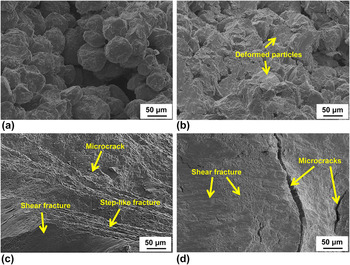
The fracture morphologies of the SLM-processed, cast, and porous (25% and 36%) composite samples after compressive testing are shown in Fig. 9. In porous samples, stress concentrations were built up in porosities and weak bonds of small cross-sectional area between the particles. Therefore, the failure of the porous compacts occurred by separation of the particles in planes 45° to the loading axis, leading to separation of the sample into small pieces. As can be seen from Figs. 9(a) and 9(b), particles in 36% porous sample underwent lower deformation compared with 25% porous sample due to smaller and weaker contact areas between the particles. Analysis of the fracture morphology in SLM-processed and cast composite samples showed that failure happened due to generation of the microcracks. Figure 9(c) reveals that the SLM-processed specimens failed mainly due to shear fracture in some regions and a step-like fracture. The typical fracture surface of the cast composite [Fig. 9(d)] exhibited a mixture of shear fracture and microcracks. During compression, the flow stress increased due to load transfer from the matrix to reinforcing TiB particles. As the external stress causes dislocations to proliferate, the spacing among them decreases and hence a higher stress is required for further deformation of the samples. In our work, Ti as the ductile phase contributed to plasticity and TiB as the hard phase dominated the strength like in the study of He et al. Reference He, Löser and Eckert39 It appears that the combination of the high plasticity resulted from the α-phase and the strength of both TiB and the Ti/TiB interface was able to accommodate the deformation until the ultimate strength. Further deformation would trigger the TiB particles to fracture and the particle/matrix interface to tear due to insufficient strength which led to the production and propagation of cracks until the final fracture of the cast and SLM-processed specimens.
SEM compressive fracture features of (a) 36% and (b) 25% porous Ti–TiB composite samples, and (c) SLM-processed and (d) cast Ti–TiB composite samples.

IV. CONCLUSIONS
In this study, in situ Ti–TiB composites were manufactured by casting, PM, and SLM technologies from starting Ti–TiB2 powder. XRD results showed that there was a chemical reaction between Ti and TiB2 which commenced around 800 °C and completed approximately at 1100 °C in which TiB particles embedded in an α-Ti matrix were produced, leading to the formation of an in situ Ti–TiB composite. XRD results of all the samples by these three technologies evidenced that all peaks corresponded only to α-Ti and/or TiB and SEM microstructural investigations indicated that TiB particles exhibited a needle-shape morphology. In addition, electron diffraction pattern by TEM evidenced that all boride particles were only TiB. SLM-processed and cast samples showed comparable mechanical properties especially in terms of Young's modulus and strength and these values were superior to those of composite samples produced by PM. The decrease in elastic modulus and strength of PM-processed composite samples can be attributed to existence of porosities. 29–36% porous composite sample showed low elastic moduli close to that of human bone. Mechanical properties of all samples produced by the three processing routes indicated that SLM-processing was able to produce composite parts of almost dense with properties similar to those of casting technology. Fractography analysis showed that porous samples failed due to weak bonds between particles as well as relatively large number of the porosities. On the other hand, SLM-processed and cast samples exhibited a mixture of shear fractures and microcracks after appreciable work hardening.
ACKNOWLEDGMENTS
The authors thank Dr. A. Waske for her technical support and S. Donath and A. Pöhl for their technical assistance. This research was supported under the Australian Research Council's Projects funding scheme (DP110101653). It has further benefited from support of the European Commission (BioTiNet-ITN G.A. 264635) and through the Deutsche Forschungsgemeinschaft (SFB/Transregio 79, Project M1).