Introduction
The MIMO technology is a well-known solution for enhancing channel capacity in the presence of a scattering environment. Printed planar MIMO antennas are preferred by the researchers due to their low cost, uncomplicated amalgamation with other wireless components and low profile. Designing wideband MIMO antennas for portable devices is challenging as closely positioned compact radiators exhibit strong mutual coupling leading to meager intra element isolation. Mitigating mutual coupling in UWB-MIMO antenna is quite demanding and several techniques such as implementing electromagnetic band-gap structure [Reference Li, Feresidis, Mavridou and Hall1], polarization diversity [Reference Zhu, Li, Feng, Deng and Yin2], slots on the radiator with a parasitic metallic patch at the back [Reference Zhang, Zhang, Tian and Luo3], modified ground plane with slots, i.e. Defected Ground Structure (DGS) [Reference Liu and Wang4, Reference Wani and Kumar5] and stub [Reference Kumar and Chakraborty6], decoupling networks [Reference Wang, Du, Yang, Ma, Zhao, Cui and Xi7, Reference Radhi, Nilavalan, Wang, Al-Raweshidy, Eltokhy and Aziz8], slotted radiator with open-circuited stub connected to the ground [Reference Khan, Capobianco, Iftikhar, Shubair, Anagnosto and Braaten9], bi-planar radiator structure [Reference Jehangir and Sharawi10], and non-planar suspended line (NPSL) [Reference Zhang and Pedersen11] have been reported to improve isolation [Reference Nadeem and Choi12] in two elements antennas.
The suspended line technique was first introduced by Diallo et al. [Reference Diallo, Luxey, Thuc, Staraj and Kossiavas13] for improving isolation between two elements non-planar MIMO antenna having non-modified ground plane structure. But it is difficult to lower mutual coupling in wideband with this conventional NPSL. A suspended line technique employed in a non-planar antenna system by Zhang and Pedersen [Reference Zhang and Pedersen11] reported >22 dB isolation with high-quality factor. However, an increase in Q factor degraded impedance bandwidth covering only lower UWB within 3.1–5 GHz range. The proposed non-planar antenna configuration by Zhang and Pedersen [Reference Zhang and Pedersen11] seems physically unrealistic for its practical implementation in compact portable devices.
This paper introduces modified PSL technique-based two elements UWB-MIMO antenna covering huge wideband from 3.1 to 11.5 GHz. Isolation measurements with proposed PSL technique register remarkable improvement up to 11 dB as compared to without using PSL technique. The proposed antenna system is employable in portable UWB systems.
Configuration of MIMO antenna
The two elements MIMO antenna proposed in Fig. 1 comprises of two co-located symmetrical radiators printed on easily available inexpensive FR-4 substrate (having 0.02 as dielectric loss tangent value, “ɛr” = 4.4 and a thickness “H” = 1.6 mm) with the common partial ground plane. These radiators are hybrid structures designed utilizing combinations of circular and rectangular discs. A PSL consisting of two thin metallic strips and a rectangular metal plate has been employed to connect these antennas. An electromagnetic coupled ESSR has been employed adjacent to feed line of both radiators in order to produce band-notching function at 5.4–5.9 GHz WLAN band and a duo of “Y”-shaped strips employed within the circular ring of the radiators is utilized to band-notch targeted 7.15–7.75 GHz for satellite downlink operations in X-band.
Configuration and fabricated prototype of MIMO antenna with proposed PSL.

To corroborate the proposed MIMO antenna, CST MWS has been used for simulations. The optimized parameters for the two element antenna design are Ws = 36 mm, Ls = 20 mm, Lp = 8 mm, Wp = 13 mm, r = 6 mm, Wf = 1.8 mm, Lf = 7.57 mm, Rp = 6 mm, Wn = 12 mm, Wh = 8 mm, Lg = 6 mm, L 1 = 3 mm, Wt = 3 mm, p = 0.64 mm, Rx = 2.0 mm, Ry = 3.7 mm, R 3 = 1.0 mm, t = 0.5 mm, R 2 = 2.0 mm, and R 1 = 3.0 mm.
Antenna design evolution
Firstly, a conventional circular monopole antenna has been chosen as basic radiating element (antenna-1) with overall size 20 × 18 × 1.6 mm3 as shown in Fig. 2(a). The lower edge frequency of this planar antenna has been derived by using the following equation [Reference Kumar and Ray14]:

Here, “L 1” = 2r and “r 1” = r/4 denote length and equivalent radius (in cm) of conventional equivalent cylindrical monopole antenna whereas “fg” = 0.157 cm is feed line length from the bottom of circular patch disc to the rectangular ground plane (Fig. 2(a)). The value of the lowest resonating frequency “FL” obtained from equation (1) is around 5 GHz that matches with simulated results shown in Fig. 3 but this antenna exhibits poor impedance bandwidth of 5–10.7 GHz. Further, the ground plane width of antenna-1 has been extended to create resonance near 3 GHz covering lower UWB spectrum (Fig. 2(b)). This circular monopole (antenna-2) exhibits huge impedance bandwidth (with S 11 < −10 dB) covering 2.5–11 GHz except impedance mismatch at 4.2–5.2 GHz (see Fig. 3). To avoid the mismatching, a rectangular disc has been added to the circular monopole to configure antenna-3 as presented in Fig. 2(c). Antenna-3 exhibits improved impedance matching from 4.2 to 5.2 GHz due to changed surface currents distribution. In the next step, similar hybrid monopole antenna comprising of circular and rectangular discs has been positioned 9 mm away from the first antenna for the MIMO application (antenna-4). The antenna-4 exhibits good impedance bandwidth from below 2 to 11.2 GHz as illustrated in Fig. 3 but obtains extremely poor isolation below 7 GHz as presented in Fig. 4. So, in order to improve isolation, a PSL consisting of two thin metallic strips and a rectangular metal plate has been employed to connect these antennas. Antenna thus formed (antenna-5) covers 3.5–11.7 GHz range with good isolation above 20 dB till 8.8 GHz (Fig. 4). However, the isolation value for antenna-5 moves above the recommended threshold value beyond 9.5 GHz.
The design steps in the evolution of the proposed MIMO antenna.

S 11/S 22 parameter of antenna-1 to antenna-6.

S 12/S 21 parameters of the antenna-4 to antenna-6.

To improve the isolation further in 9.5–11.7 GHz range, an “I”-shaped slot has been cut in PSL to form antenna-6. Along with “I”-shaped slot in the PSL, a duo of “Y”-shaped protruded strips are employed within a circular ring in the radiator; and an elliptical ESSR has been placed near the feed line of individual radiating elements to exhibit band notching in WLAN and X-band applications. This final antenna covers 3.5–11.5 GHz range with more than 21 dB isolation in the almost entire range of operation. On comparing the isolation curves from antenna-5 and antenna-6, it has been noticed that at 8.2 GHz both antennae have isolation of almost 21.8 dB and beyond 8.2 GHz the isolation of antenna-6 improves to a large extent as compared to antenna-5. This validates the significant isolation improvement by utilizing slotted PSL technique in the proposed antenna.
Band notching function
To avoid electromagnetic interference from coexisting WLAN and X-bands, half-wavelength resonators have been employed having a total length calculated by equation (2):

having

Here, L λn/2 total is the length of employed half-wavelength resonator for notching targeted center frequency (fnotch) of the desired band; “c” speed of the light is 3 × 10⁸ m/sec; “H” is thickness of substrate; “ɛeff” and “ɛre” are effective and the relative dielectric constants. Due to compact MIMO antenna dimensions, the targeted band-notching functions have been achieved through appropriate positioning of the half-wavelength resonators such that the effect of the mutual coupling between the resonators in limited space is efficiently reduced. The total length of the single elliptical split-ring resonator “Lessr” employed for band-notching WLAN band is $L_{essr} = 2 \times \pi \;\times \sqrt {( {R_x^2 + R_{y\;\;\;}^{2\;\;} } ) /2} \;-p-t$ = 17.51 mm, which is quite close to 16.3 mm calculated value from equation (2). The total length for band notching downlink X-band with 7.5 GHz center frequency, using equation (2), is 12 mm. The dimensions of “Y”-shaped structure in the radiator have been optimized to get a perimeter of 11.5 mm as illustrated in Fig. 1. This validates the dimensions of “Y”-shaped half-wavelength slot resonator.
Mutual coupling reduction by PSL
The rectangular slotted metal disc in the proposed PSL allows the flow of decoupling currents through numeral different electrical path lengths; which cancels out-coupling currents on the surface of the ground plane. Thus, an effective wideband decoupling phenomenon has been achieved. The reported UWB/wideband–MIMO antennas employing suspended lines in [Reference Zhang and Pedersen11, Reference Nadeem and Choi12] contribute toward small impedance bandwidths. But proposed PSL supports planar configuration with huge impedance bandwidth (3.5–11.5 GHz) due to its specific optimized design structure with “I”-shaped slot in the center that can be employed in compact systems.
Surface currents distributions
The antenna surface current distribution in the presence of ESSR and a pair of “Y”-shaped strips is illustrated in Fig. 5 for notched frequencies at 5.6 and 7.5 GHz, respectively, while port number 2 has been energized and the port number 1 has been matched terminated through load impedance of 50 Ω. These employed band-notching structures modify the capacitive and inductive values of antenna input impedance and provide additional current paths. At notched frequencies, oppositely directed currents along these structures cancel the resultant radiating fields and hence generate the band-notch functions. The band-notch frequencies and bandwidth of the notched bands can be easily controlled by varying the dimensions of ESSR and adjusting the electromagnetic coupling amid the duo of “Y”-shaped strips employed within the circular ring of radius R 1 in Fig. 1 for desired notched bands.
Current distribution in notched frequencies when port 2 is energized: (a) 5.6 GHz, (b) 7.5 GHz. (Current scale is the same as Fig. 7.)

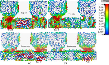
The decoupling performance of the proposed PSL can be studied intuitively by surface current distribution at various frequencies. Figure 6 shows the surface current distribution without and with PSL when port 1 is excited. It is noticeable that the proposed PSL has effectively suppressed coupling currents flow from radiator 1/port 1 to radiator 2/port 2 leading to reduced mutual coupling effect.
Current distribution with and without wideband suspended line. (Current scale is the same as Fig. 7.)

The current distributions in ground plane at 10 GHz with port 1 excited (a) without “I”-shaped slot, (b) with “I”-shaped slot.

The fundamental principle of mutual-coupling reduction through PSL is the field cancellation amid the neighboring elements which plays a vital role in decoupling the current paths among the adjacent radiating elements. This field cancellation can be explained by the direction of surface currents on the partial ground plane, and a central rectangular disc of PSL in between two radiating elements. These currents are in opposite directions as seen in Fig. 7(a) at 10 GHz.
So, resultant coupling fields cancel out and this field cancellation by PSL alters the impedance characteristics of the antenna and mitigates the total flow of surface currents toward co-located port. This reduces the mutual coupling among antenna elements hence improves isolation. Additionally, it can be noticed that the “I”-shaped slot has lead to the high density of decoupling currents on a rectangular metallic disc of the neutralization line (Fig. 7(b)) resulting in strong decoupling field at higher frequencies.
Experimental results with discussions
Proposed MIMO-antenna has been characterized through Rohde & Schwarz (ZVA-40) vector network analyzer. The simulated scattering parameters have been compared with measured values for two elements MIMO configuration in Fig. 1. Good concurrence is found amid these results as depicted in Fig. 8 except some discrepancies owing to fabrication and soldering losses. Measured results depict that impedance bandwidth for two elements MIMO antenna system is 8.4 GHz (covering 3.1–11.5 GHz) with >21 dB isolation between co-located antenna elements in UWB range accompanying band-notching in 5.45–5.85 GHz of WLAN band and in 7.15–7.95 GHz for X-band downlink range for satellite communication.
Scattering parameters values for proposed MIMO configuration with band notching functions.

Influences on isolation by proposed PSL
Proposed PSL structure with central metallic rectangular plate with “I”-shaped slot has been designed by performing parametric analyses on PSL width “Wn” and slot widths “Wh” and “s” through CST MWS. Results from the analysis have been presented in Fig. 9. From Fig. 9(A) it is clear that isolation between the ports is the highest for “Wn” = 12 mm for the entire operating band; whereas isolation is poor at higher frequencies for “Wn” = 10 mm, and for “Wn” = 14 mm, the isolation values at lower frequencies are not satisfactory. So “W n” = 12 mm has been chosen as optimized width of the PSL.
Effect from the variation of “Wn”, “Wh”, and “s” on the isolation of MIMO antenna.

The “I”-shaped slot is inserted in the PSL to influence the isolation values at higher frequencies due to change in surface current distributions as seen in Fig. 6 and Fig. 7(b). Influence of widths “Wh” and “s” has been depicted in Figs 9(b) and 9(c), respectively. It is noticeable that for “Wh” = 6 mm, the isolation values are low beyond 10 GHz. For “Wh” = 10 mm, the isolation curve is poor beyond 8 GHz. Isolation has been further improved by optimizing and finally choosing “W h” = 8 mm; which gives isolation values >21 dB for desired frequency ranges.
Slot width “s” influences the high-frequency region beyond 8 GHz (Fig. 9(c)). It can be seen that improved isolation has been obtained for “s” = 2 mm as compared to “s” = 1 or 3 mm which yield inferior isolation results.
Initially, parametric analysis on several values of “Wn” from 6 to 18 mm has been investigated according to the space available between the individual antenna elements. After studying and comparing obtained results, selective values of “Wn” have been distinguished and presented in Fig. 9(a) to show the influence of “Wn” dimensions on the isolation. Similarly, the selection of a range of dimensions for parametric analysis on “Wh” and “s” depends on the optimal values chosen for “Wn” and “Wh”, respectively, which exhibit best isolation curves within the 3.1–10.6 GHz UWB frequency range.
It has been noticed that for high isolation, the individual antenna elements are separated by distance “d” = 0.093 λat 3.1 GHz mm and placed on 0.062 λat 3.1 GHz × 0.372 λat 3.1 GHz mm2 ground plane (Fig. 1). In the printed planar antennas, the current distribution on the ground plane plays a significant role in controlling radiation patterns, gain, and improvising impedance matching [Reference Ellis, Zhao, Wu, Nie and Liu15]. So, in order to investigate the role of antenna physical dimensions for high isolation, parametric analysis has been performed on the width “Ws” of the ground plane [Reference Diallo, Luxey, Thuc, Staraj and Kossiavas13]. The dimensions of “Ws” have been changed such that the increase in “Ws” further increases the distance “d” between the individual antennas and vice versa; without affecting the dimensions of the individual antenna elements. It can be noticed in Fig. 10 that decreasing “Ws” to 32 mm (in terms of operating wavelength Ws = 0.33 λat 3.1 GHz mm, d = 0.05 λat 3.1 GHz mm) has lead to poor isolation in lower 3.1–5 GHz UWB frequency region. This is specifically due to an increase in mutual coupling because of small distance “d” between the antenna elements. The current distributions at 3.5 GHz for different dimensions of “Ws” have been shown in Fig. 10 to demonstrate the effectiveness of separation distance “d”.
Effect due to the variation of “Ws” and “d” on the isolation of MIMO antenna. (Current scale is the same as Fig. 7.)

Increasing “Ws” to 40 mm (i.e. Ws = 0.41 λat 3.1 GHz mm, d = 0.13 λat 3.1 GHz mm) has improved isolation in lower 3.1–5 GHz UWB frequency region due to low mutual coupling between antenna elements owing to large distance “d” between the antenna elements. However, for the chosen dimension of proposed antenna “Ws” = 36 mm (i.e. Ws = 0.37 λat 3.1 GHz mm, d = 0.09 λat 3.1 GHz mm), the isolation remains below 21 dB for entire UWB band which is not the case for “Ws” = 32 mm and “Ws” = 40 mm. Hence, it can be observed that specific dimensions of the ground plane results in different isolation values and is an important parameter for the antenna system.
Influence on band notch characteristics by proposed notching structures
The variation in gap “r” separating the duo of “Y”-shaped band-notched structure in individual antenna significantly influences the electromagnetic coupling (Fig. 5(b)) and hence influence the notched frequencies values. As “r” is varied from 0.6 to 1.4 mm (see Fig. 11(a)), the center notched-frequency increases due to decrease in $\matrix{ {L_{\lambda n/2\;total}} \cr }$ according to equation (2). Small electromagnetic gap size when “r” = 0.6 mm yields undesirable band-notching at 6.68–7.07 GHz and a large value of “r” = 1.4 mm leads to an undesirable band-notching at 7.53–8.2 GHz higher frequencies band. However, with “r” = 1 mm, required band notching at 7.15–7.75 GHz has been obtained.
Effect due to variation of (a) “r” and (b) “Rx” on the notched bands of MIMO antenna.

The elliptical radius “Rx” of electromagnetic coupled ESSR has been varied and optimized for desired band notching characteristics as depicted in Fig. 11(b). When the radius “Rx” is varied as 1.85–2.0 mm; the band notched-frequency decreases with desired band-notched characteristics obtained at width “Rx” = 2 mm. The optimum results are obtained at “R x” = 2.0 mm which notches 5.45–5.9 GHz band.
Radiation patterns
The two-dimensional radiation patterns form MIMO antenna at port 1 have been plotted in principle xz and yz-planes at various frequencies in Fig. 12. It is evident from Fig. 12 that radiation patterns at low frequencies are monopole like, and at a notched frequency of 7.5 GHz, measured patterns of radiation are not omni-directional. At higher frequencies, E-plane (here yz-plane) lobe are spitted and H-plane (here xz-plane) pattern are nearly omni-directional owing to higher-order modes.
Radiation patterns of MIMO element at port 1.

MIMO performance analysis
To validate the potential of the proposed antenna configuration for the MIMO application; attaining low values of Envelope Correlation Coefficients (ECC) becomes essential. The ECC value represents the measure of correlation of different communication channels. However, ideal value of ECC is zero; but practically ECC values must lie below 0.5 to ensure good MIMO performance. ECC values have been numerically calculated for isotropic and Gaussian statistical models using complex three-dimensional radiation patterns and have been shown in Fig. 13. An isotropic or uniform wireless channel has uniform power distributions for incoming waves (i.e. Pθ and P ϕ = 1/4π) with unity Cross-Polarization Discriminator (XPR) value [Reference Sharawi16], and has been computed using equation (4):

Here Ei (θ, ϕ) represents complex three-dimensional radiated field pattern from ith antenna. Equation (3) is valid for isotropic wireless environment. However, considering environmental effects, a more generalized expression (4) given by Sharawi [Reference Sharawi16] is used:
 $${\rm ECC\;}( {{\rm \;}\rho_e} ) = \left \vert {\displaystyle{{\mathop{{\int\!\!\!\!\!\int}\!\!{\circ}} {{\rm XPR} \times E_{\theta_m}( {\rm \Omega } ) E_{\matrix{ {\theta_n} \cr } }^{\rm \ast } ( {\rm \Omega } ) P_\theta ( {\rm \Omega } ) + E_{\matrix{ {\phi_m} \cr } }( {\rm \Omega } ) E_{\matrix{ {\phi_{n}} \cr } }^{\rm \ast } ( {\rm \Omega } ) P_\phi ( {\rm \Omega } ) d{\rm \;}{\rm \Omega }} } \over {\sqrt {[ \mathop{{\int\!\!\!\!\!\int}\!\! {\circ}} {{\rm XPR} \times G_{\theta_m}( {\rm \Omega } ) {\rm \;}P_{\matrix{ \theta \cr } }( {\rm \Omega } ) + G_{\phi_m}( {\rm \Omega } ) {\rm \;}P_{\matrix{ \phi \cr } }( {\rm \Omega } ) {\rm \;}d{\rm \;}{\rm \Omega }} {\rm \;}] } \sqrt {[ \mathop{{\int\!\!\!\!\!\int}\!\!{\circ}} {{\rm XPR} \times G_{\theta_n}( {\rm \Omega } ) {\rm \;}P_{\matrix{ \theta \cr } }( {\rm \Omega } ) + G_{\theta_n}( {\rm \Omega } ) {\rm \;}P_{\matrix{ \phi \cr } }( {\rm \Omega } ) {\rm \;}d{\rm \;}{\rm \Omega }} {\rm \;}] } }}} \right\vert . $$
Here, XPR is the vertically polarized and the horizontally polarized ratio of radiated field components; P θ, ϕ (Ω) signifies the wave distributions at the particular angular (θ, ϕ) direction and Gθ, ϕ (Ω) represents gain (i.e. Gθ = Eθ (Ω) Eθ (Ω)*). For ECC calculations, Gaussian power distribution with XPR equal to 1 dB in an outdoor environment and XPR value of 5 dB for indoor environments [Reference Mathur and Dwari17] have been used. For the isotropic environment, the ECC values have found to lie below 0.1 and the maximum ECC values derived using equation (5) for the Gaussian outdoor and indoor environments are 0.19 and 0.15, respectively, which indicate good diversity characteristics.
ECC versus frequency curves for the isotropic and Gaussian environments.

Diversity gain (DG) values of the proposed MIMO configuration have been evaluated through ECC values from Fig. 13 using equation (6) and plotted in Fig. 14.

Diversity gain versus frequency curves.

The obtained diversity gain values for the isotropic environment are above 9.98 dB. For Gaussian outdoor environment (XPR = 1 dB) and indoor environment (XPR = 5 dB), the diversity gain values are above 9.91 and 9.92 dB, respectively. However, the diversity gain values at center band-notched frequency decrease to 9.95 in the isotropic environment, and reduce to 9.83 and 9.89 dB in the Gaussian outdoor and indoor environment, respectively, due to band-notching functions.
Figure 15 presents radiation efficiency and measured gain for the proposed UWB-MIMO antenna. Efficiencies of both radiators from port 1 and 2 are almost identical. MIMO antenna gain shows variation from 1.8 to 3 dB.
The efficiency values and the realized gain values of MIMO antenna.

Figure 16 presents the measured Channel Capacity Loss (CCL) which determines upper bound on the total rate of information transmitted efficiently via the communication link. This CCL has been derived from the measured S-parameters [Reference Zhou, Quan and Li18] using equation (7):

Here, $\;{\bf \psi }^{\bf R}$ represents 2 × 2 correlation matrix.
Channel Capacity Loss versus frequency plot.

Elements of ${\bf \psi }^{\bf R}$ are calculated from ${\bf \psi }_{{\bf ii}} =$
 (1 –|S ii|2–|S ij|2) and ${\bf \psi }_{{\bf ij}}$
 = $-( {S_{ii}^\ast \;\;S_{ij} + S_{ji}^\ast S_{jj}} )$
 ,
with i and j = 1 or 2.
The value of capacity loss should be below the threshold value of 0.4 bits/s/Hz. Obtained measured values of the CCL are below 0.27 bits/s/Hz in whole UWB band, except in notched frequency bands where CCL value is quite high.
Table 1 draws attention toward uniqueness in this work by comparing proposed MIMO-antenna performances and the references. The proposed antenna is quite compact than antennas mentioned in [Reference Li, Feresidis, Mavridou and Hall1, Reference Zhu, Li, Feng, Deng and Yin2, Reference Liu and Wang4–Reference Radhi, Nilavalan, Wang, Al-Raweshidy, Eltokhy and Aziz8, Reference Jehangir and Sharawi10, Reference Zhang and Pedersen11, Reference Mathur and Dwari17] and has better isolation than antennas discussed in [Reference Li, Feresidis, Mavridou and Hall1–Reference Wani and Kumar5, Reference Khan, Capobianco, Iftikhar, Shubair, Anagnosto and Braaten9, Reference Jehangir and Sharawi10, Reference Mathur and Dwari17]. Moreover, the proposed antenna covers the entire UWB range but antennas in [Reference Li, Feresidis, Mavridou and Hall1, Reference Jehangir and Sharawi10, Reference Zhang and Pedersen11] cover only a small part of the UWB region. Proposed MIMO-antenna achieves dual band-notching characteristics whereas band-notching property is reported in few references [Reference Zhu, Li, Feng, Deng and Yin2, Reference Wani and Kumar5, Reference Mathur and Dwari17] only and rest other reported works are prone to electromagnetic interferences from co-located narrowband applications. Also, the suggested antenna configuration with PSL covers huge bandwidth than other reported suspended line employed UWB-MIMO configurations in [Reference Zhang and Pedersen11, Reference Nadeem and Choi12].
Comparison with other UWB–MIMO antenna designs.

Conclusions
A new compact UWB-MIMO antenna exhibiting high isolation due to a modified PSL and dual band-notched characteristics has been proposed. Band notching has been obtained for WLAN band due to ESSR placed near feed lines and for X-band satellite downlink operations due to the duo of “Y”-shaped strips employed in radiators. To the best of our information, this antenna achieves the largest impedance bandwidth among all the UWB/wideband-MIMO antennas in literature employing suspended line techniques. Measured efficiency, ECC, DG, and CCL reflect that proposed PSL technique is practical for effectively reducing mutual-coupling effect in the UWB-MIMO antenna systems.
Acknowledgements
The authors are greatly thankful to Prof. (Dr.) Kumar V. Srivastava, I.I.T. Kanpur, India and Prof. (Dr.) Deepak Bhatnagar, University of Rajasthan, India for supporting and providing required research facilities to complete this work. The authors heartily thank Dr. A. K. Sharma – Ex Scientist G, CSIR-CEERI Pilani-India, for critical evaluation and suggesting refinements in this manuscript.
 Kirti Vyas received the M.Tech. degree in Electronics and Communication from Malaviya National Institute of Technology, Jaipur, Rajasthan, India. Presently she is a professor at Arya College of Engineering and I.T., Kukas, Jaipur (Rajasthan) and has about 30 international papers to her credit. Her main research interests are the design and optimization of planar antennas and arrays.
 Dr. Rajendra Prasad Yadav received his Ph.D. degree from MREC Jaipur (University of Rajasthan) and M.Tech. degree from the Indian Institute of Technology Delhi. Currently, he is working as Professor-HAG, in the Department of Electronics Engineering, Malaviya National Institute of Technology, Jaipur (Rajasthan), India. He was instrumental in formulating Ph.D. Ordinances and starting research work in RTU Kota as Vice-Chancellor. He has 70 research publications to his credit. His research interests are Error Control Codes and MIMO-OFDM, RF and Antenna Systems, Mobile and Wireless Communication Systems, Optical Switching and Materials, Mobile Adhoc and Sensor Network, Device Characterization and MEMS.