Introduction
Printed monopoles are one of the most popular antenna configurations for many wireless devices [Reference Weiner1]. They are simple, low cost, omni-directional, and characterized with wide operational bandwidth. The feeding of printed monopole antennas has been suggested in different configurations including microstrip and coplanar waveguide (CPW), where they aim for optimum impedance matching and radiation pattern properties over the entire antenna bandwidth [Reference Abdalla, Ibrahim and Boutejdar2–Reference Zahran, Abdalla and Gaafar9]. Monopole antenna can be adapted for multi-band functionalities by incorporating it with other resonators. Examples for these designs are: (1) folding of monopole [Reference Park, Kang and Sung10, Reference Deng, Liu, Zhang and Tentzeris11], which is limited in design capabilities; (2) using different defecting ground radiating resonators [Reference Liu, Wu and Dai12, Reference Chang and Kiang13], yet it may increase the antenna size; (3) integrating slots with the monopole for achieving extra resonances [Reference Mehdipour, Sebak, Trueman and Denidni14, Reference Moosazadeh and Kharkovsky15]; nevertheless, it is complex in design and leads to a complex structure when using bottom layer [Reference Hu, Wu, Zheng and Ren16]; and (4) integrating inspired metamaterial resonators with monopole [Reference Zhu and Eleftheriades17–Reference Abdalla, Hu and Muvianto20].
With needed multi-band functionalities, there is a need to have good isolation between the nearby bands. Cascading the antennas with band-stop filters is one direct solution for this objective [Reference Abdalla and Fouad21–Reference Jiang, Gregory and Werner25]. However, this approach results in a larger, overall, structural size. Hence, there is always a need for self-filtering antennas [Reference Abdalla26–Reference Deng, Hou, Zhao and Guo30].
Split-ring resonator (SRR) has become a very popular resonating structure with the introduction of artificial engineered metamaterial structures [Reference Pendry, Holden, Robbins and Stewart31]. From another aspect, SRR has a high-quality factor compared to other resonators; thus, it can act as a sharp band-stop filter and can be applied in antenna filtering applications [Reference Abdalla, Fouad, Elregeily and Mitkees32]. SRR has been used in designing multi-band monopole-based antennas [Reference Kim and Varadan33–Reference Kim, Kim, Yang and Ahmad35].
From the previous discussion, a need for dual wide-bands with good band-stop filtering characteristics between them is a good approach to emphasize [Reference Hu and Hua36–Reference Hu, Pan, Wa and Zhang39]. In [Reference Abdalla, El-Sobky and El-Gabry40], the employment of coupled SRR particles was introduced as proof of concept of a dual-band with wide-band filtering characteristics.
In this paper, we introduce a detailed design, analysis procedures, and measurement properties of the dual wide-bands and band-stop filtering characteristics in-between the bands. The antenna functionality is based on a concept of coupled SRR particles in which they play an important role in achieving high matching quality (almost 0 dB band-stop between the two bands of interest). The dual bands are selected for covering different wireless services. The analytical principles/3D electromagnetic simulations using the commercial full-wave simulator and experimental measurements are presented in the paper. The evolution of the proposed coupling mechanism effects is discussed in section “Coupled SRR-based antenna design”. The final design is discussed in section “The highly selective dual-band double coupled SRR-based antenna results” and the filtering/radiation properties are discussed in section “The highly selective dual-band double coupled SRR-based radiation properties”.
Coupled SRR-based antenna design
In this section, one order of SRR particles is introduced. The purpose of this antenna design is to achieve single/double bands which can be used for different wireless services. The design starts with an initial design of a single SRR monopole antenna to resonate at 3 GHz. This SRR radiator will be coupled to another concentric SRR to excite the second radiating band.
Single-band SRR-based monopole antenna design
The geometry of a single-loop SRR particle is shown in Fig. 1(a) and its equivalent circuit is shown in Fig. 1(b). When employing the SRR particle as a monopole antenna radiator, the SRR diameter was set close to a quarter wavelength as in (1). However, the air gap capacitor reduces the resonant frequency for the same SRR diameter. Based on the equivalent circuit of the SRR resonator in Fig. 1(b), the resonant frequency can be re-calculated as in (2), where the values for L and C are the SRR inductance and gap capacitor, respectively. The antennas are printed on the FR-4 substrate with a dielectric constant of 4.4 and a substrate thickness of 0.8 mm.


The SRR: (a) particle geometry; (b) particle equivalent circuit; (c) single monopole antenna top view (Gr = 0.6 mm, Wt = , G= and Lg = 11.5 mm, Wg = 14 mm, Wt = 3 mm, Ws = Ls = 30 mm. The radii Rx = 8.4 mm, R = 9 mm (for a single outer SRR antenna) or Rx = 6.4 mm, R = 7 mm (for single inner SRR antenna)).

Therefore, to have a monopole at 3 GHz, the loop diameter should be in the order of 20–30 mm. It is worth to comment that this value will be optimized through full-wave simulations.
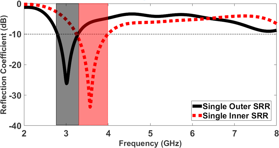
To demonstrate the frequency resonance functionality of the SRR particle, the two different-sized SRR-based monopole antennas shown in Fig. 1(c) were simulated. Both antennas have the same overall size of 30 mm × 30 mm and are fed by a 50 Ω CPW transmission line. In the first case, the monopole has the SRR radii Rx = 8.4 mm and R = 9 mm. These dimensions were selected such that the resonance frequency in (1) is set to 3 GHz. In the following presented results, this studied case is referred to as a single outer SRR case. The simulated reflection coefficient of the single outer SRR monopole antenna is shown in Fig. 2 (solid black). As shown in the figure, the antenna resonates at 3 GHz at which the reflection coefficient is −26 dB.
The simulated reflection coefficient of the two studied cases (single inner SRR antenna and a single outer SRR antenna).

In a second studied case, the SRR radii were R = 7 mm and Rx = 6.4 mm. This case is denoted single inner SRR case. The simulated reflection coefficient of the single inner SRR antenna is shown in Fig. 2 (dotted red). In the figure, it can be observed that the resonance frequency, with −34 dB reflection coefficient, shifts to 3.6 GHz.
It is noted that the −10 dB reflection coefficient bandwidth is quite similar in the two cases; 2.75–3.35 GHz (19.7%) pertaining to the first case, while 3.25–4 GHz (20.1%) for the second case. Accordingly, the SRR monopole can demonstrate a reasonable wide-band antenna. Furthermore, beyond the antenna bandwidth frequencies, the reflection coefficient goes close to −5 dB over a wide frequency band of up to 7 GHz.
Radiation mechanism: inner SRR antenna gap orientation effect
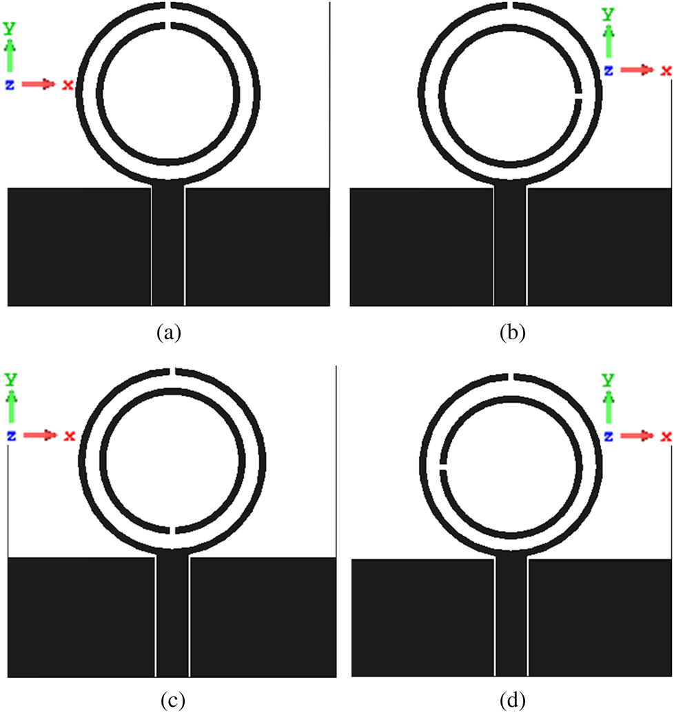
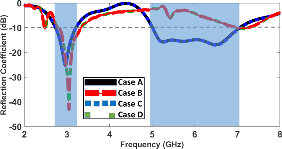
The air-gap orientation, of the inner SRR antenna, plays a capacitive role in achieving the second wide-band resonance in addition to the coupling phenomena. This is explained thoroughly in this section. The gap separation between the two SRR particles is set to be 1.4 mm. Besides the standard case, referred to as case A where the inner SRR gap is along the same orientation as the outer one, three other cases were studied, cases B, C, and D. The layouts of all four cases are displayed in Fig. 3. In Fig. 4, due to symmetry, case A (solid black) and case C (dotted blue) displayed the same reflection coefficient performance, as well as exhibited the same realized gain and total efficiency values. Both case B (dashed red) and case D (dotted with gaps green) show similar performance.
The proposed antenna layout with inner SRR air gap, with respect to the center, at: (a) positive y-axis (case A); (b) positive x-axis (case B); (c) negative y-axis (case C); (d) negative x-axis (case D).

The simulated reflection coefficient of case A (solid black), case B (dashed red), case C (dotted blue), and case D (dotted with gaps green).

Figure 4 illustrates that there is a dual-band resonance achieved when the inner SRR antenna gap is orientated along the same axis as the outer SRR antenna one (case A – solid black) and similarly case C, while a single-band resonance is attained when there is a 90° phase shift between both gaps (case B – dashed red) and similarly case D. Therefore, for the sake of brevity, cases A and B are benchmarked in terms of all performance parameters. In case A, not only can the antenna demonstrate two operating bands, but also there is a good filtering stopband between them with close to 0 dB attenuation at mid-frequency. These resonance properties are the main contributions of the proposed design.
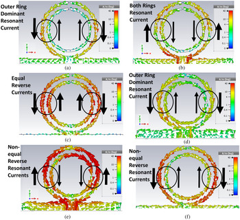
To explain the antenna operation mechanism, we emphasize in the following part the current distribution at 3 GHz (1st band mid-frequency), 6 GHz (2nd band mid-frequency), and 4.5 GHz (the stopband between the two operating bands mid-frequency) as shown in Figs 5(a)–5(c), respectively.
The coupled SRR antenna current density distribution at: (a) case A (3 GHz); (b) case A (6 GHz); (c) case A (4.5 GHz); (d) case B (3 GHz); (e) case B (6 GHz); (f) case B (4.5 GHz).

In Fig. 5(a) pertaining to case A at 3 GHz, it is obvious that the dominant current is within the outer ring rather than the inner one, and hence, the antenna resonance mechanism is close to that presented in Fig. 2 of the single outer SRR antenna.
In Fig. 5(b) pertaining to case A at 6 GHz, it can be noticed that the current density at the inner SRR particle increases compared to the 3 GHz case in Fig. 5(a). This means more coupled current from outer SRR to inner SRR is satisfied. In addition, the currents in the two rings have no resonance nature, and hence, it can be claimed that the second band resonance mechanism is the overall/coupling of the outer/inner rings. This explains how due to the coupling mechanism, the second wide-band in Fig. 4 of case A, from 5 to 7 GHz, is wider than the resonance band in single inner SRR antenna, in Fig. 2, from 3.25 to 4 GHz.
In Fig. 5(c), it can be observed that the two currents in outer/inner rings are antiparallel so that they contribute to a complete band-stop filtering response. In other words, this confirms the non-radiation (total reflection) antenna at this frequency and hence the creation of the stopband.
On the other hand, current distributions for those of case B at 3, 6, and 4.5 GHz are shown in Figs 5(d)–5(f), respectively. The current in Fig. 5(d) is close to that in Fig. 5(a) which can support the same resonance at 3 GHz. In Fig. 5(e), the current in the outer/inner rings has no similarity/dominant current/resonance so that it agrees with no matching at 6 GHz as observed in Fig. 4. A similar observation is concluded from the current distribution at Fig. 5(f).
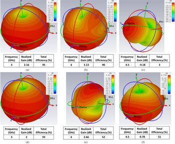
The radiation mechanism is further verified by exploring the radiation properties of all studied cases in Fig. 5. The 3D simulated gain patterns of cases A and B at 3 and 6 GHz, respectively, are displayed in Fig. 6, along with the realized gain and total efficiency values. The conventional omni-directional pattern, with nulls along the y-axis, is maintained at 3 GHz for case A (gain = 2.16 dB), case B (gain = 2 dB), and at 6 GHz for case A (gain = 3.13 dB). These three results agree with former current distributions in Figs 5(a), 5(b), and 5(d). At Fig. 6(c), the omni-directional pattern is almost disappeared and gain drops to −9.18 dB which also agrees with anti-current resonance in Fig. 5(c). On the other hand, there is a high deformation at 6 GHz for case B due to no efficient radiation, which agrees with the current distribution in Fig. 5(e). Same results can be observed at 4.5 GHz at case B in Fig. 6(f). This is further illustrated, as the total efficiency severely drops from −0.1 dB, case A at 6 GHz (Fig. 6(b)) to −2.1 dB, case B at 6 GHz (Fig. 6(e)).
The coupled SRR antenna simulated 3D gain pattern at: (a) case A (3 GHz); (b) case A (6 GHz); (c) case A (4.5 GHz); (d) case B (3 GHz); (e) case B (6 GHz); (f) case B (4.5 GHz).

Radiation mechanism: gap separation effect and analysis
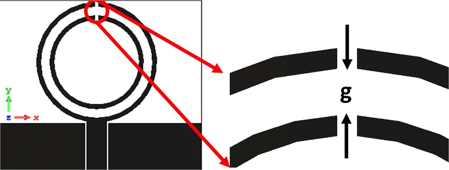
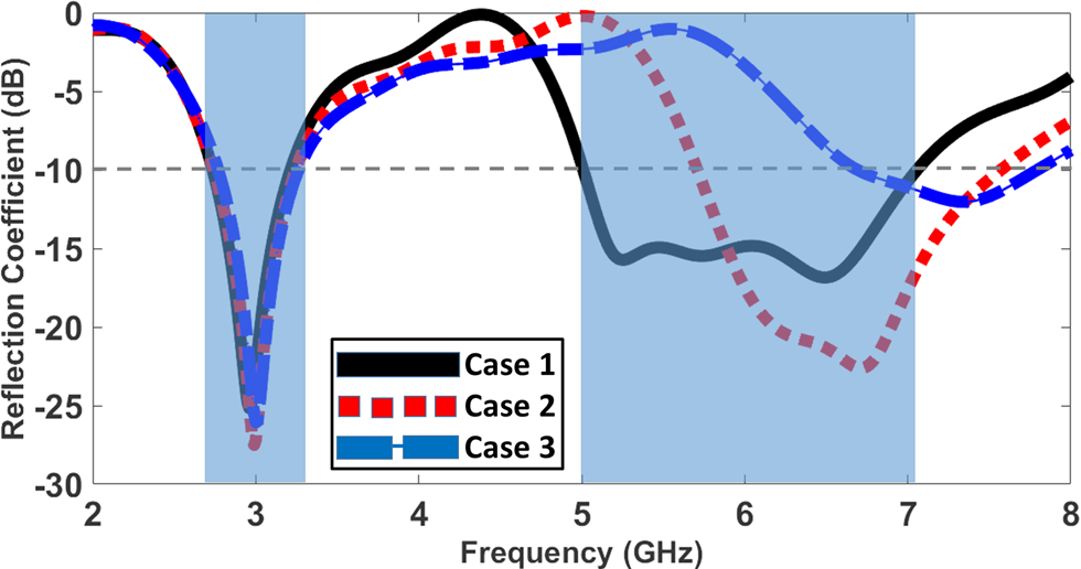
In the previous section, we validated the effect of current distribution in the two SRR (case A), where it leads to a coupling between the two SRR elements, which eventually results in (1) a second operating band at 6 GHz and (2) a 0 dB stopband at the two bands at 4.5 GHz (mid-frequency). This conclusion will be further emphasized in this section by varying the gap separation between the two SRR elements. Hence, three studied cases of gap separation, denoted as “g”, in-between the two SRR elements (case 1 is for g = 1.4 mm, case 2 is for g = 2.4 mm, and case 3 is for g = 3.4 mm) are displayed in Fig. 7. In the simulated reflection coefficient, demonstrated in Fig. 8, it can be seen that all studied cases have the first resonance at 3 GHz where it is explained earlier as a cause of the outer SRR antenna. However, the gap separation has a direct effect on the second wide-band resonance and the level of stopband in-between. All cases confirm that a dual-band functionality is possible by this configuration. At g = 2.4 mm (case 2), the second band is shifted to 6.7 GHz and the 0 dB band-stop frequency is shifted to 5 GHz. By increasing the gap separation to 3.4 mm (case 3), the second band resonance becomes non-significant and the stopband does not show 0 dB. In other words, there is no effective function coupling between the two SRR antennas.
Study of the gap separation effect on coupled SRR antenna.

The simulated reflection coefficient of the three different cases, case 1 (g = 1.4 mm), case 2 (g = 2.4 mm), and case 3 (g = 3.4 mm).

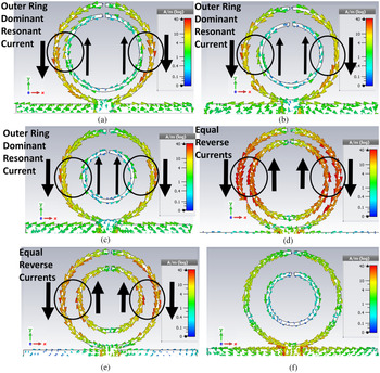
This effect is further justified by analyzing the behavior of the surface current distribution at the center frequency of first band (3 GHz) in Figs 9(a)–9(c) for cases 1, 2, and 3, respectively. It is clear that the three cases have the same current pattern, which is dominant at outer SRR element, that confirms the agreement in reflection coefficient of the three bands at 3 GHz shown earlier in Fig. 8. The current distribution at mid-frequency of the stopband is 4.5 GHz in Fig. 9(d) for case 1, 5 GHz in Fig. 9(e) for case 2, and 5.4 GHz in Fig. 9(f) for case 3. The comparison between case 1 at 4.5 GHz in Fig. 9(d) and case 2 at 5 GHz in Fig. 9(e) confirms that in both cases, the two currents in the two SRR elements are equal and reverse. This observation confirms the 0 dB reflection coefficient and hence band-stop filter at 4.5 and 5 GHz for the two cases shown in Fig. 8. For case 3 at 5.4 GHz in Fig. 9(f), the reverse current between the two SRR elements becomes insignificant which also agrees with no 0 dB reflection coefficient in Fig. 8.
The coupled SRR antenna current density distribution at: (a) case 1 (3 GHz); (b) case 2 (3 GHz); (c) case 3 (3 GHz); (d) case 1 (4.5 GHz); (e) case 2 (5 GHz); (f) case 3 (5.4 GHz).

The realized gain and total efficiency at boresight are plotted for the whole frequency band, 2–8 GHz, in Figs 10 and 11, respectively. As can be seen at 3 GHz, the realized gain and total efficiency are the same in all cases, 2.16 dBi and −0.24 dB, respectively, and are not affected by the coupling. This is not the case at 6 GHz, since the realized gain drops from 3.44 dBi (case 1) to 1.67 dBi (case 3). In addition, the total efficiency drastically reduces from −0.1 to −3 dB.
The simulated double coupled SRR antenna realized gain of the three different cases, case 1 (g = 1.4 mm), case 2 (g = 2.4 mm), and case 3 (g = 3.4 mm).

The simulated double coupled SRR antenna total efficiency of the three different cases, case 1 (g = 1.4 mm), case 2 (g = 2.4 mm), and case 3 (g = 3.4 mm).

The highly selective dual-band double coupled SRR-based antenna results
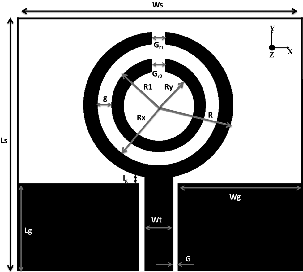
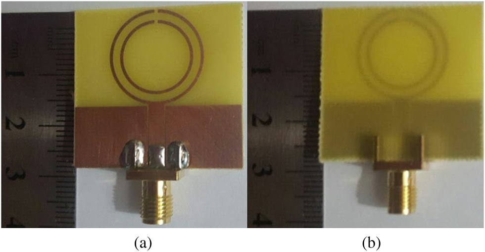
From the previously demonstrated results, the radiation mechanism of the double coupled SRR antenna has been proven. In this section, the results of the final proposed dual-band antenna are emphasized. The top view geometry of the proposed coupled SRR dual-band antenna is shown in Fig. 12. The outer SRR monopole is directly excited by a 50 Ω CPW transmission line, whereas the inner one is excited by the coupled current from the outer SRR. The detailed dimensions are shown in the figure, where it is noticed that the largest SRR radius is 9 mm and the guided wavelength in the FR-4 substrate is 54.4 and 27.2 mm at 3 and 6 GHz, respectively. Therefore, the ratio of the largest dimensions ranges from one-third to one-sixth. In other words, it can be claimed that the SRR sub-wavelength criterion is valid at lower frequencies and partially at higher frequencies. Hence, the antenna structure is explained as inspired metamaterial, not ideal metamaterial. The fabricated antenna prototype is shown in Fig. 13 (top and bottom views, respectively). The antenna is printed on the same employed FR-4 substrate with 0.8 mm thickness and with the same overall size of 30 mm × 30 mm.
The 2D layout of the double coupled SRR antenna layout (Gr1 = Gr2 = 0.6 mm, Wt = 3 mm, G = 0.25 mm, Lg = 11.5 mm, Wg = 14 mm, Ig = 0.33 mm, g = 1.4 mm, Ws = Ls = 30 mm, Rx = 8.4 mm, R = 9 mm, RY = 6.4 mm, R1 = 7 mm).

The fabricated double coupled SRR antenna prototype: (a) top view; (b) bottom view.

The double coupled SRR antenna resonance is illustrated by simulating and measuring its reflection coefficient as shown in Fig. 14. As can be observed, the antenna has two resonance bands within which the reflection coefficient is lower than −10 dB. Both simulated and measured results demonstrate that the first band is extending from 2.75 to 3.15 GHz and the second band from 5 to 7 GHz. Also, it can be observed that there is a clear stopband between the two operating bands. This stopband has a maximum isolation (reflection coefficient is almost 0 dB) at 4.5 GHz and −3 dB bandwidth from 3.9 to 4.7 GHz. This means that the filtering of the two bands can be done at 0.75 GHz (3.9–3.15 GHz) for the first band and at 0.3 GHz (4.7–5 GHz) for the second band. It is clear that there is a very good agreement between the simulated and measured results. However, it has to be claimed that some small discrepancies can be observed between simulated and measured reflection coefficient in higher band. These differences are mostly below −10 dB and do not affect the overall results. These differences are mainly due to imperfections in fabrication and the use of FR-4 substrate.
The simulated and measured reflection coefficients of the double coupled SRR antenna.

It is worth to claim that not only the dual-band/self-isolation functionalities of the proposed antenna are satisfied successfully, but also compared to conventional single-band quarter-wavelength monopole antenna at 3 GHz (diameter = 13.6 mm), the proposed antenna radiator is 57% smaller.
In summary, the motivation of using the SRR in our antenna design is (1) making use of its loop resonance to have resonant mode at radiating frequencies and (2) making use of its filtering properties at stopband frequencies.
The highly selective dual-band double coupled SRR-based radiation properties
The radiation properties of the coupled SRR dual-band antenna are examined by studying the far-field of the antenna at the two center frequencies; 3 and 6 GHz in Figs 15 and 16, respectively. The simulated and measured normalized 2D radiation patterns in the two principal planes, E-plane (YZ (∅ = 90°)) and H-plane (XZ (∅ = 0°)), at 3 GHz in Figs 15(a) and 15(b) and at 6 GHz in Figs 16(a) and 16(b), respectively, are illustrated. The measurements were done using near-field measurements employing the StarLab Antenna Measurement – MVG. At 3 and 6 GHz, the normalized figure-of-eight gain polar pattern is illustrated for both simulated and measured results in the E-plane, whereas the normalized isotropic gain polar pattern is attained for both results in the H-plane.
The normalized simulated and measured gain radiation patterns of the double coupled SRR antenna at 3 GHz in: (a) YZ-plane; (b) XZ-plane.

The normalized simulated and measured gain radiation patterns of the double coupled SRR antenna at 6 GHz in: (a) YZ-plane; (b) XZ-plane.

Portrayed in Fig. 17 is a comparison between the simulated and measured realized gain. Both curves follow the same pattern, where it is noticed that the simulated values (2.2 and 3.44 dBi for the solid black curve) are higher than the measured values (dotted red curve), at 3 and 6 GHz, respectively. Nevertheless, the measured values are highly acceptable for wireless applications. This pattern is also consistent at 4.5 GHz, where the very low measured realized gain of −25 dBi is a clear indication of no radiation at this specific frequency, hence stopband. Furthermore, the simulated total efficiency (blue dashed curve), expressed in percentage for ease of illustration and comparison with recently published work, is almost 95 and 97.5% at 3 and 6 GHz, respectively, while it falls to almost 0% at 4.5 GHz. These numbers confirm the good potential of the proposed antenna for wireless applications. With all these presented results and analysis, it can be confirmed that the antenna exhibits good radiation performances promoting it as a good candidate for wireless communication.
The double coupled SRR antenna simulated and measured realized gain and simulated total efficiency.

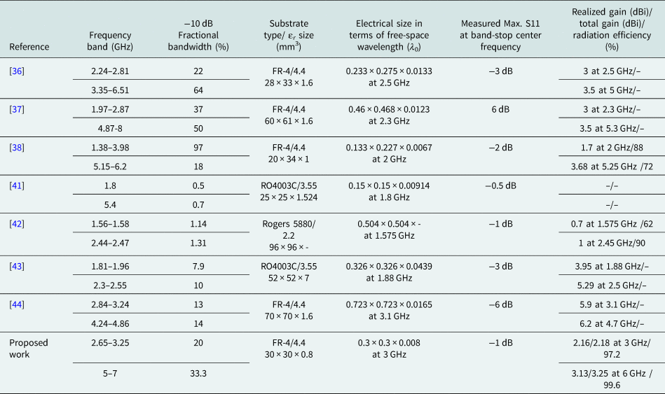
A summary of the proposed self-filtering dual-band double coupled SRR antenna performance compared to recent relevant published work is presented in Table 1. Comparison criteria factors include the frequency band, −10 dB fractional bandwidth, substrate type, physical size, maximum reflection coefficient at the band-stop center frequency, realized gain, and radiation efficiency. From the presented data, the antenna is distinguished with high out-of-band suppression compared to other relevant work. Also, it can be claimed that the proposed antenna has good radiation efficiency in the two bands. The antenna is competitive with the relevant work in physical size and bandwidth.
Performance of the proposed antenna compared to recent published wide-/dual-band antennas

Conclusion
Analysis of coupled SRR antennas has proven how a single SRR monopole antenna is adapted for dual-band coupled SRR particles antenna. The antenna has proved to possess two wide-bands from 2.65 to 3.25 GHz (20%) and from 5 to 7 GHz (33%). The two bands are separated by a high out-of-band suppression (high rejection up to 0 dB reflection coefficient) at 4.5 GHz. The antenna exhibits very good monopole-like radiation properties within its two operating bands. At the center frequencies of both bands, the antenna radiation efficiency is almost 0 dB and the realized gain is 2.2 and 3.4 dBi at 3 and 6 GHz, respectively. Moreover, the antenna has low cost, simple structure, and compact in size, which all contribute to applying it in industrial wireless applications.
 Mahmoud A. Abdalla was born in 1973, received the B.Sc. and M.Sc. degrees in electrical engineering from Military Technical College, Cairo, Egypt in 1995 and 2000. He received the Ph.D. degree from the School of Electrical Engineering, University of Manchester, UK, in 2009. He is now a professor leading the electromagnetic waves group in the Electronic Engineering Department, Military Technical College. Dr. Mahmoud was the recipient of Egyptian encouragement state prize for engineering sciences in 2014. He published more than 200 peer-reviewed journal and conference papers. His research focuses on miniaturized, multiband, and wideband microwave/millimeter antennas and components and also absorbing materials employing metamaterial/EBG structures. He is a senior member of the IEEE/URSI and the European Microwave Association EuMA. He is a reviewer in many high ranked journals where he was awarded the top 1% Publon worldwide reviewer award for 2018 and 2019.
 Mohamed Z. El Atrash received the B.Sc. (with honors) in electrical engineering from the Electrical Systems Engineering Department, October University for Modern Sciences and Arts (MSA), Cairo, Egypt, in 2011. He also received the M.Sc. degree (with distinction) in wireless mobile communications systems engineering from the University of Greenwich (UoG), UK, in 2014. Currently, he is pursuing his Ph.D. degree in electrical engineering at Ain Shams University, Cairo, Egypt. His research interests include flexible wearable antennas, high gain, thin, low profile antennas, and EBG/AMC design. Out of his research, he published articles in the Transaction on Antennas and Propagation, IET Microwaves, Antennas & Propagation, and the International Journal of Microwave and Wireless Technologies, as well as a number of conference papers. He is a reviewer in the IET Microwaves, Antennas & Propagation, where he has reviewed 11 journals.
 Nour A. El-Sobky received the B.Sc. degree in electrical engineering from the Electrical Systems Engineering Department, October University for Modern Sciences and Arts (MSA), Cairo, Egypt, in 2016. She is working now as an incident handling engineer fl CBE. She is currently pursuing her M.Sc. degree in the Arab Academy for Science and Technology department of electrical and communication engineering, Cairo, Egypt.
 Sherif R. Zahran was born in 1991. He received the B.Sc. and M.Sc. degrees, with a grade of excellent, from the Arab Academy for Science and Technology department of electrical and communication engineering, Cairo, Egypt in 2013 and 2017, respectively. Additionally, he was with Huawei starting from 2015 till 2018 and with Ericsson till 2019 as a 2G, 3G, and LTE configuration back office engineer. He is currently pursuing his Ph.D. studies in a joint industrial program which includes University of Calabria (Italy), University of Grenoble Alpes (France), and SIAE Microelettronica (Italy). The current focus is on developing high-gain wideband antennas for mm-wave backhauling applications. Sherif has more than 3 years of experience with flexible/wearable wideband monopole antennas and SAR calculations. Sherif has published more than 14 publications in the field of antennas since 2014 and has been a reviewer for IEEE Transactions on Antennas and Propagation since 2019.