I. INTRODUCTION
Thin films have long been popular research objects for studying the scale dependence of the mechanical properties of materials. The scientific interest has recently grown to a new dimension, as thin films are becoming more and more pivotal in a large number of consumer goods, prompting a strong industrial demand for assessing their reliability.
Most of the research on the fatigue properties of thin films has so far been performed on samples attached to a substrate, with the main focus on copper films and to a lesser extent on gold and silver films. The same general trends have in fact been found for these materials. Thick films usually display similar extrusions and voids at the free surface as known from macroscopic samples.Reference Schwaiger, Dehm and Kraft1,Reference Schwaiger and Kraft2 Transmission electron microscopy observations, for instance by Zhang et al.Reference Zhang, Volkert, Schwaiger, Wellner, Arzt and Kraft3 on 3 µm copper films, hint at a similar mechanism of formation of walls and cells dislocation structures. Such similitudes disappear for thinner copper films. In the transition regime corresponding to a thickness of 200 nm–1 µm in copper, the dislocations are more randomly organizedReference Zhang, Volkert, Schwaiger, Wellner, Arzt and Kraft3 and extrusions are more rarely found on the surface.Reference Schwaiger, Dehm and Kraft1 Last, for copper films below 200 nm, damage formation is mostly localized at interfaces such as grain boundaries or twin boundaries.Reference Zhang, Volkert, Schwaiger, Wellner, Arzt and Kraft3,Reference Lu, Suo and Vlassak4 The explanation that has been proposed for explaining the transition in cyclic deformation mechanisms is that the dimensional and microstructural constraints become too strong to allow the formation of organized dislocation structures.Reference Kraft, Schwaiger and Wellner5 The typical formation of extrusions as described by MughrabiReference Mughrabi6,Reference Mughrabi7 for macroscopic samples is indeed based on the formation of persistent slip bands, which in bulk copper have a characteristic wall-spacing of 1.4 µm.Reference Winter8 Since the yield strength of thinner films is also higher, these might not be able to deform plastically until a high stress is reached, which is larger than the stress needed for cracking at grain boundaries.Reference Lu, Suo and Vlassak4 This could explain why grain boundary cracking dominates the fatigue life, while some extrusions can still form if testing is continued after cracking has occurred.Reference Sim, Hwangbo, Kim, Lee and Vlassak9 A general observation is that very thin films tested with the same stress amplitude exhibit a longer fatigue life than thicker ones,Reference Schwaiger and Kraft2 whichever definition is adopted for fatigue life.Reference Sim, Hwangbo, Kim, Lee and Vlassak9,Reference Sun, Wang, Zhang, Liu, Zhang, Ding, Zhang and Sun10 While the general picture of the size effect is clear, there are certain factors that can influence its magnitude or the thickness range for the transition. A good adhesion of the film to the substrate can for instance postpone the local debonding that is needed for the slip bands to develop and thus extend the fatigue life of the sample and possibly change the failure mode to grain boundary cracking.Reference Sim, Hwangbo, Kim, Lee and Vlassak9 Another interesting finding from Lu et al.Reference Lu, Wang, Suo and Vlassak11 is that as-deposited copper films with an unstable microstructure are not very fatigue resistant. Such films are indeed subject to local abnormal grain growth during testing, which leads to the creation of weak spots (Hall–Petch effect), where the deformation is immediately localized and extrusions can grow.
Freestanding films with submicrometer thickness have yet hardly been investigated,Reference Abbas, Leseman and Mackin12–Reference Lin, Tong and Shiu14 largely due to the difficult sample handling. As a consequence, their fatigue behavior remains largely unknown. In recent years, the bulge test has emerged as an appropriate technique for investigating the monotonic mechanical properties of very thin freestanding films.Reference Kraft and Volkert15 It therefore makes sense to also apply it to the study of their fatigue properties.
II. BULGE TESTING
The self-built experimental setup that has been used for this study relies on gaseous nitrogen for pressurizing a membrane. It can be operated in two distinct modes: ex situ, the deflection of the membrane is continuously measured by a laser autofocus displacement sensor and in situ, the whole setup is inserted into a Dimension 3100 atomic force microscope (AFM; Bruker, Santa Barbara, CA), which enables imaging the surface of the sample under load. The experimental setup has been described in more detail elsewhereReference Schweitzer and Göken16 and has also been used to measure the fracture toughness of very thin filmsReference Merle and Göken17 in a similar way as pioneered by previous authors.Reference Liddle, Huggins, Mulgrew, Harriott, Wade and Bolan18,Reference Xiang, McKinnell, Ang and Vlassak19
As for the present study, cyclic testing is achieved by repeating a triangular pressure pattern a given number of times. The use of a fast settling exhaust valve allows an operating frequency of 0.2 Hz, which is twice as high as that found for a bulge tester with comparable gas pressure actuation.Reference Kalkman, Verbruggen and Janssen20 Higher frequencies are difficult to achieve with the current experimental setup, due to the limited permitted gas flow. This is the reason why the setup is preferentially used for low cycle rather than high cycle and ultrahigh cycle fatigue testing.
The tested samples have a 4 × 1 mm rectangular geometry and a thickness between 100 and 400 nm, which justifies using the analytical model of a long rectangular membrane developed by Vlassak et al.Reference Vlassak and Nix21,Reference Xiang, Chen and Vlassak22 This model enables calculating the lateral stress σxx and strain εxx of the film from the pressure-deflection data recorded during the experiment:
 $${{\rm{\sigma }}_{xx}} = {{p{a^2}} \over {2ht}}\quad ,$$
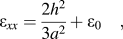 $${{\rm{\varepsilon }}_{xx}} = {{2{h^2}} \over {3{a^2}}} + {{\rm{\varepsilon }}_0}\quad ,$$
where a is the half-width of the membrane, t its thickness, p the applied gas pressure, and h the deflection in the center of the membrane, as indicated in Fig. 1(a). In case the film consists of a bilayer and the mechanical properties of one layer are known, it can easily be shown that the stress experienced by the second layer σxx,2 is given by:
 $${{\rm{\sigma }}_{xx,2}} = {t \over {{t_2}}}{{\rm{\sigma }}_{xx}} - {{{t_1}} \over {{t_2}}}{{\rm{\sigma }}_{xx,1}}\quad ,$$
i.e.,
 $${{\rm{\sigma }}_{xx,2}} = {{p{a^2}} \over {2h{t_2}}} - {{{t_1}} \over {{t_2}}}\left[ {{{{E_{{\rm{Y1}}}}} \over {{\rm{1}} - {\rm{\nu }}_{\rm{1}}^2}} \cdot {{2{h^2}} \over {3{a^2}}} + {{\rm{\sigma }}_{0,1}}} \right]\quad ,$$
where E Y1 is the known Young's modulus, ν1 the Poisson's ratio, and σ0,1 the residual stress of the underlying layer of the sample, see Fig. 1(b). In addition to the implementation of these equations, the script used for the evaluation of the stress–strain data implements a correction for the machine compliance and for an initial height offset.Reference Small and Nix23
Schematic of the central section of a long rectangular membrane during bulge testing: (a) single layer and (b) bilayer membrane.

III. SAMPLE PREPARATION
The samples consisting of a 1 × 4 mm rectangular membrane held by a silicon frame were fabricated by micromachining. In a first step, a silicon wafer was coated on both sides with nonstoichiometric “low-stress” LPCVD (low pressure chemical vapor deposition) SiNx. Next, rectangular openings were then patterned on the backside by means of photolithography, and the silicon was finally etched away from this area with potassium hydroxide. These first two steps were outsourced to Silson Ltd. (Northampton, U.K.). The resulting freestanding SiNx film was either directly tested in the bulge test or used as a substrate for the deposition of gold. The latter was performed using a PVD MED-020 (Balzers Oerlikon, Liechtenstein) evaporation device. A thin chromium adhesion layer (<10 nm) and a much thicker gold film (>100 nm) were successively deposited without interrupting the vacuum. The bilayer gold–SiNx membranes were tested from this condition, while the freestanding gold films required further processing. In this case, both SiNx and chromium were removed from the backside of the membrane by hot phosphoric acid etching. This resulted in the gold film being totally freestanding in the rectangular section and firmly bonded to the frame anywhere else. As already well-documented in the literature, the deposition process used for the gold films resulted in a strong (111) fiber textureReference Kocks, Tomé and Wenk24 and a predominantly columnar microstructure.Reference Movchan and Demchishin25
IV. EXPERIMENTAL RESULTS
A. Validation of the bulge fatigue test with SiNx membranes
To validate the new bulge fatigue testing method, measurements were carried out on a plain SiNx membrane. Amorphous LPCVD-SiNx is indeed known from the literature to have an almost infinite fatigue life,Reference Chuang, Fettig and Ghodssi26,Reference Chuang, Fettig and Ghodssi27 thus making it a perfect material for testing the long-term stability of the experimental setup. In detail, a 100-nm-thin SiNx film was tested at 0.2 Hz with a maximum pressure of 50 kPa. The membrane withstood 105 cycles—corresponding to 6 days—without failing. The plane-strain modulus and residual stress calculated for each cycle are shown in Fig. 2(a). The periodic scattering visible in the residual stress data of Fig. 2(a) results from short interruptions of the test after every 500th cycle for pressure calibration purposes. The plane-strain modulus and the residual stress level remain absolutely constant throughout the whole test. Further interesting information is available from the comparison of the stress–strain diagrams calculated for every 10,000th cycle, as shown in Fig. 2(b). First of all, the loading and unloading segments are linear and overlap perfectly, confirming that the deformation of SiNx is indeed purely elastic. The lack of hysteresis more importantly proves that no significant machine effects are occurring. Secondly, the diagrams of all cycles overlap extremely well. This is a confirmation that LPCVD SiNx is not affected by fatigue or by cracking, which would have resulted in a reduction in stiffness and a modification of the slope of the segments. More importantly, it shows that the fatigue test device is very stable over long periods of time.
Quantitative evaluation of the fatigue test of a 100 nm SiNx film at 0.2 Hz and 50 kPa: (a) plane-stress modulus and residual stress evolution; (b) stress–strain loops for every 10,000th cycle (the first cycle is skipped as it corresponds to the initial monotonic-like deformation).
B. Thin gold films bonded to a SiNx substrate
1. Bulge fatigue testing
Similar cyclic tests were performed on gold films bonded to a SiNx substrate. All in all, about ten gold samples with a thickness between 100 and 300 nm were tested on a 100-nm-thick SiNx substrate. Since the results are very similar, only a representative test on a 100-nm-thick gold film will be presented here. This sample was pressurized up to 100 kPa at a frequency of 0.2 Hz. The reason why the maximum pressure was chosen higher than that of the plain SiNx films is that the total thickness was larger. The recorded experimental data was evaluated by Eq. (4), which allowed extracting the contribution of the gold film under the verified assumption that the mechanical properties of the SiNx substrate remain constant throughout the test. The most important results of the quantitative evaluation are reported in Fig. 3. First of all, it should be noted that the membrane did not fail during the whole 50,000 cycles of testing. This is a general behavior: other samples have even been tested up to 200,000 cycles without failure. The obvious reason is that the SiNx substrate has an almost infinite fatigue life and can bear the full load on its own. As shown in Fig. 3(a), the scattering in the data appears to be quite large, which is a consequence of the extrapolation of the contribution of the gold layer from the deformation of the overall composite membrane. It can however clearly be seen that the plane-strain modulus remains constant throughout the test. The measured value of 100 GPa is higher than the data found in the literature for macroscopic polycrystalline gold samples (93 GPa according to Ref. Reference Callister28). However, this is consistent with the fact that the sample has a strong (111) texture component: according to the equations provided in Ref. Reference Merle, Schweitzer and Göken29, a sample with a pure (111) texture would have a plane-strain modulus as high as 121 GPa (elastic constants from Ref. Reference Simmons and Wang30). Anyway, the stability of the measured plane-strain modulus throughout testing indicates the lack of large cracks and delamination from the substrate. The residual stress shifts in contrast to larger and larger compressive values, although the initial state of the as-deposited sample was tensile (+100 MPa). This evolution is very fast during the first 3000 cycles and continues further, albeit at a decreasing rate. This shift toward more compressive residual stresses can be interpreted as the result of an increased elongation of the film due to successive plastic deformation. This is confirmed by the observation of the hysteresis loops shown in Fig. 3(b), showing a progressive shift toward higher strains. Interestingly, both strain increment and plastic strain amplitude continuously decrease with increasing number of cycles. These combined observations of cyclic creep and cyclic hardening of the film are usually referred to as ratcheting. Another interesting observation from Fig. 3(b) is that supported gold films are subjected to a stress alternating between tension and compression, unlike the freestanding films that can only be loaded in tension. The reason is that, when loaded beyond its yield strength, gold flows plastically, while the brittle SiNx substrate continues to deform purely elastically. When the load is removed, the SiNx film contracts and pulls the strongly bonded gold layer into compression.Reference Xiang and Vlassak31,Reference Hommel, Kraft and Arzt32
Quantitative evaluation of the fatigue test for a 100 nm gold film on SiNx at 0.2 Hz and 100 kPa: (a) plane-stress modulus and residual stress evolution and (b) stress–strain loops for every 5000th cycle.
2. Microscopic observations
The gold films on SiNx substrates were investigated in the AFM and the scanning electron microscope (SEM) before and after testing. AFM observations revealed that the fatigue tests amounted to a slight uniform roughening of the gold surface. It should be pointed out that the topography recorded by the AFM does not necessarily reflect the underlying microstructure of the sample. The mean grain size is usually larger than the structures visible on the surface, as evidenced by comparing Figs. 4(a) and 4(c). The hillocks seen at the surface originate from the early condensation islands created during film deposition. The roughening observed during the fatigue test therefore does not correspond to grain growth. This effect is anyway very limited in magnitude: in the representative case of the film shown in Figs. 4(a) and 4(b), the roughness R a increased from 1.1 to 1.5 nm only.
Topography of a 120-nm-thick gold layer on SiNx investigated by AFM: (a) before fatigue testing, (b) after 290,000 cycles at Δp = 50 kPa, and (c) backscattered electron image taken before testing, showing the underlying microstructure.
In addition to this uniform roughening, localized damage formation was observed on several samples tested at a range of 100 kPa. Typical micrographs are shown in Fig. 5. Very thin films of about 100 nm thickness show the growth of hillocks [Fig. 5(a)] and whiskers [Fig. 5(b)] from the surface. Such a behavior is frequently encountered for stressed aluminum and lead films, most of the time—but not always—at elevated temperature.Reference Eberl, Spolenak, Arzt, Kubat, Leidl, Ruile and Kraft33–Reference Kim, Heiland, Nix, Arzt, Deal and Plummer35 It is obviously caused by the compressive stress reached in the film upon unloading of the pressure, which induces the material to flow out of plane. Thicker films of about 300 nm thickness show extrusions forming inside very large grains [Figs. 5(c) and 5(d)]. Their occurrence in the largest grains is not a coincidence, as plasticity is facilitated there by the Hall–Petch effect. A similar localization in large grains has been observed by Lu et al.Reference Lu, Wang, Suo and Vlassak11 in copper films tested on a polymer substrate.
Localized damage formation during fatigue testing of supported gold films with different thicknesses. (a and b) Hillock and whisker formation in a 100 nm gold film and (c and d) extrusions in very large grains of a 300-nm-thick gold film.
C. Freestanding gold films
1. Bulge fatigue testing
The freestanding gold films showed a more pronounced fatigue behavior than the films on a substrate. This is well illustrated by the measurement performed on a 230-nm-thick gold membrane tested with the same parameters as used for SiNx films (a cycling frequency of 0.2 Hz and a maximum pressure of 50 kPa). The quantitative evaluation of the test is shown in Fig. 6. This freestanding gold film failed after 34,058 cycles, corresponding to 2 days of testing. Two similar 230-nm-thick films were tested, one of which failed after 13,000 cycles only, while the second one withstood more than 70,000 cycles. It can be seen in Fig. 6(a) that the plane-strain modulus of the film remains fairly constant throughout the test, just as found for SiNx membranes and gold films on SiNx substrate. Unlike the previous cases, the evolution of the residual stress is not plotted, because it is nonexistent. The small initial tensile residual stress is indeed already eliminated by the plastic deformation taking place during the first cycle. Being freestanding, the film does not accommodate further plastic deformation by building up a compressive internal stress but would rather buckle if the pressure would be completely removed. The increase of the accumulated plastic strain appears in Fig. 6(b) as the shift to higher strains of the successive hysteresis loops. This shift follows a logarithmic law, which is consistent with cyclic creep being responsible for it. A side effect of this strain increase is that—as the bulge setup is pressure controlled—the stress and strain ranges are slightly reduced, see Fig. 6(c). In Fig. 6(b), a progressive reduction of the hysteresis and the strain increment between two consecutive loops is observed, which is attributed to cyclic hardening. Such a behavior is frequently encountered during the push–pull testing of macroscopic fcc metals samples up to the formation of persistent slip bands, provided the plastic strain range exceeds ∼10−4,Reference Mughrabi, Ackermann and Herz36 as it is the case here. On the whole, it can be concluded that the freestanding gold films experience a strong ratcheting behavior. Looking more carefully at Fig. 6(b), one can see that the very last hysteresis loop is slightly out of line compared with the previous ones, with a strain value higher than expected. This final behavior is more clearly seen if the strain data is analyzed from each cycle. Figure 6(d) shows that the plastic strain of the membrane increases at an accelerated rate over the last 2000 cycles preceding failure. This probably corresponds to strain localization leading to the final failure of the sample.
Quantitative evaluation of the fatigue test of a 230 nm freestanding gold film at 0.2 Hz and 50 kPa until failure after 34,058 cycles: (a) plane-stress modulus evolution, (b) stress–strain loops for every 2000th cycle, (c) corresponding stress and strain ranges, and (d) mean strain σxx during each hysteresis loop.
2. Microscopic observations
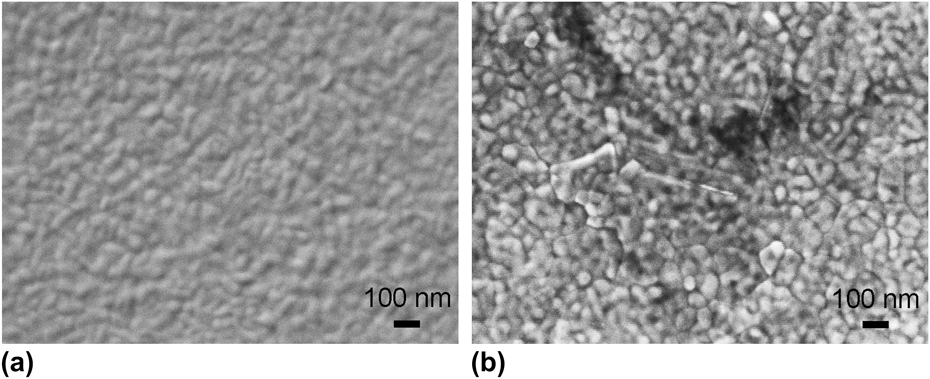
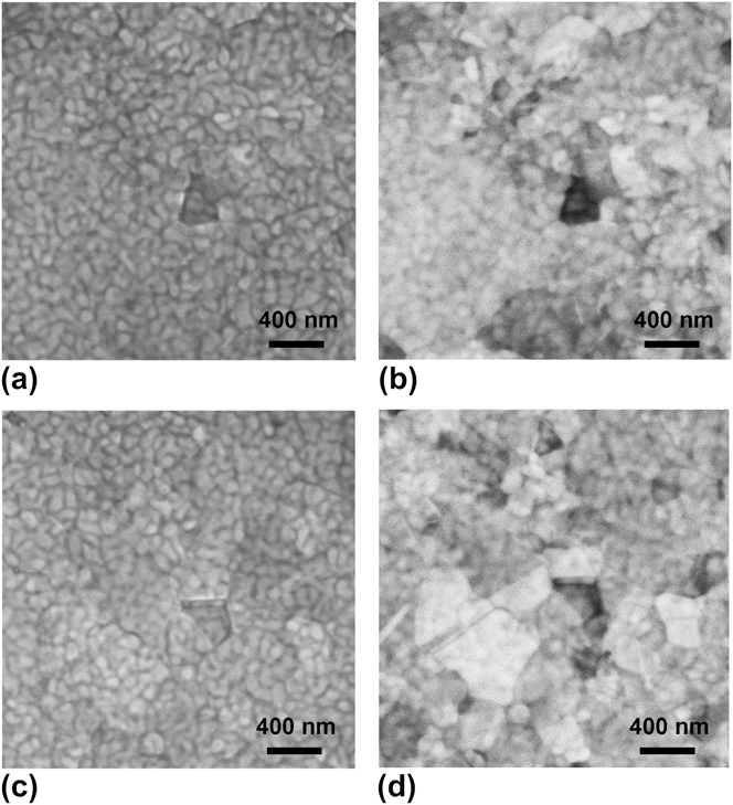
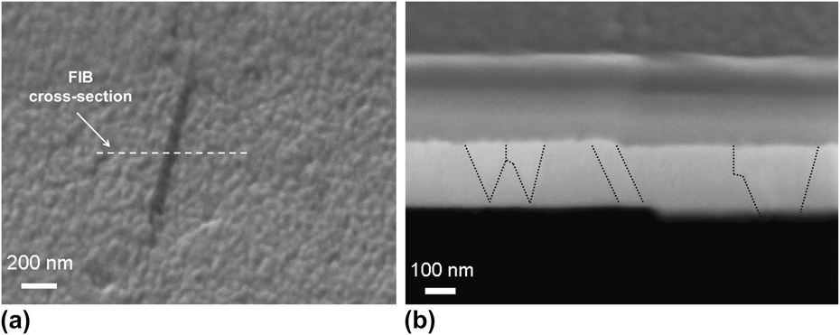
Several tests on freestanding gold films were interrupted at a periodical interval of 5000 or 10,000 cycles so as to allow inspection of the surface in the optical microscope, SEM, and AFM. The samples had a thickness of about 230 nm and were tested at a maximum pressure of 30 kPa. The first interesting observation is a progressive roughening of the film. While the surface is originally quite smooth, the grain structure becomes visible from the surface topography after a few thousands cycles, see Fig. 7. This roughening of the surface at the grain boundaries is first limited to few areas but becomes more and more widespread as testing goes on. After a longer testing time, it is found that individual grains sink below the original level of the surface at various places, see Fig. 8. This sink-in is likely to be a further step of the previously observed surface roughening. The displaced grains have a size of 200–400 nm, therefore neither falling into the categories of the largest nor the smallest grains present in the film. They also have various shapes. It is however striking that they appear rather dark on the micrographs with backscattered electron contrast, which could hint at a common orientation. Investigations by AFM directly confirmed that the contrast that was observed by secondary electron imaging was of topographical nature. Figure 9(a) shows the sink-in of a grain imaged after 70,000 cycles. The AFM cross-profile in Fig. 9(b) reveals that the surface of the displaced grain is tilted away from the horizontal, indicating grain rotation. The sharp vertical line visible on the right side of the diagram strongly suggests grain boundary sliding. A pile-up is also observed within the neighboring grain, presumably as a result of the combined rotation and gliding of the first grain along their common grain boundary. A similar sink-in event of a grain was also investigated with a focused ion beam, see Fig. 10. The cross-section reveals a step extending between both sides of the membrane, which is in line with the assumption of grain boundary sliding associated with limited plasticity. In this particular case, sliding seems to have occurred along a twin boundary. Sliding along other grain boundaries was also found, compare with Fig. 8.
SEM images of the surface: (a) before testing and (b) after 25,000 cycles, grains become visible in the topography.
SEM images after 70,000 cycles showing sink-in deformation of grains: (a and c) secondary electron contrast and (b and d) backscattered electron contrast.
AFM micrograph showing the sink-in of a grain after 70,000 cycles (a) and the corresponding cross-profile (b).
Electron microscopic and focused ion beam investigation of grain boundary sliding. (a) Top view of the surface and (b) cross-section showing a step on both sides of the film (grain boundaries visible from secondary electron contrast have been highlighted).
V. DISCUSSION
The most striking observation concerns the ratcheting behavior of all fatigue-tested gold films, which is indicative of plastic creep. The magnitudes are however very different for freestanding and SiNx-supported films, with the cyclic creep contribution being roughly 102 times higher for the investigated freestanding sample than for the corresponding supported film. The testing parameters used for both films are compared in Table I. It can be seen that they were tested at a similar mean stress level. It should however be noted that—due to the limited maximum pressure achievable with the experimental setup—a thinner film had to be used on the SiNx substrate, which implies that its microstructure was finer.Reference Merle, Schweitzer and Göken29 This probably leads to a greater strength of this sample.Reference Arzt37,Reference Nix38 In any case, the settings used for both kinds of samples correspond to low cycle fatigue testing above their initial yield limit, so the large difference in cyclic creep is not directly connected to this difference of strength, but rather to the different deformation mechanisms that have been observed.
Comparison of the main fatigue testing parameters for the freestanding and supported films discussed throughout the article. The values are related to the last cycles of the tests.
The observations performed after completion of the fatigue tests can be summarized as follows. For the gold films tested on a SiNx substrate, there is no major change in topography. The most striking modification is a uniform roughening of the surface, which is a consequence of the uniform straining of the upper gold layer by the elastic SiNx substrate. Its magnitude (0.4 nm increase of R a) however makes it nonhazardous for the fatigue life of the film. Besides this uniform roughening, only few and very localized sites of plastic activity could be detected. On films as thin as 100 nm, the formation of whiskers and hillocks was observed. The likely explanation is that material is squeezed out of the film through weak points in the microstructure when it is put under compression. Only films with a thickness of 300 nm exhibit the typical extrusions usually associated with the fatigue of coarse-grained bulk samples, and even then they are confined to some abnormally large grains with a diameter of the order of 1 μm. This is a direct hint that the development of dislocation structures requires a minimum spacing and explains why extrusions were not observed in the 100-nm-thick samples. The good adhesion provided by the chromium interlayer also makes the necessary debonding more difficult, therefore restricting the formation of extrusions. All the findings reported so far are in line with the results obtained by other researchers on thin copper and silver films on polymeric and silicon oxide substrates.Reference Schwaiger, Dehm and Kraft1,Reference Schwaiger and Kraft2,Reference Kraft, Schwaiger and Wellner5,Reference Sim, Hwangbo, Kim, Lee and Vlassak9,Reference Schwaiger and Kraft39,Reference Wang, Volkert and Kraft40 It should however be mentioned that no cracking at grain boundaries could be observed, even in the thinnest 100 nm samples. This might be because the strain range was not as high as for the experiments reported in Refs. Reference Sim, Hwangbo, Kim, Lee and Vlassak9 and Reference Wang, Volkert and Kraft40.
Freestanding films exhibit in comparison a lot of plastic damage. The deformation is mostly localized at grain boundaries and there is repeated evidence of grain boundary sliding. This mechanism is obviously favored by the columnar microstructure of the films, which results in a weak geometrical constraint against the out of plane motion of the grains. Such a motion would be unlikely in nanocrystalline bulk materials because of geometrical incompatibilities with other grains. During nanoindentation experiments, such grain boundary sliding has been exclusively observed at the free surface.Reference Maier, Merle, Göken and Durst41 Obviously, it is also unlikely to happen in a film tightly bonded to a substrate. In such a case, and provided that the deformation cannot be carried by intragranular plasticity, one would expect grain boundary cracking. Although the tested freestanding films statistically had just as many abnormally large grains as the films on a SiNx substrate, not a single extrusion could be found. This is an indication that accommodation of the stress happens more easily by deformation at grain boundaries than by intragranular plasticity.
A first consequence of the observed grain boundary sliding is that it leads to an increase in the sample length. This phenomenon therefore boosts the cyclic creep rate of the freestanding films compared with the supported films, in which grain boundary sliding cannot occur due to the tight bonding to the elastic SiNx substrate. Another reason for the slower creep rate of the supported films is that, as testing goes on, the gold film becomes increasingly plastically deformed, so a greater part of the load transfers to the substrate. This fast drop of the mean stress is clearly visible in Fig. 3(b). It reduces the driving force for creep in the gold film and is not compensated in any way by the substrate, which is elastic and does not creep. The effect would be less pronounced for a more compliant substrate. Another consequence of the localized deformation at grain boundaries is the associated strong roughening of the surface, which is likely to cause strain localization leading to an early failure of the film. This might account for the poorer fatigue life of the freestanding sample, although it was tested at stress and strain ranges half as large only as for the SiNx supported film (see Table I). A comprehensive study of the fatigue life of the films would require constructing S–N curves, which did not prove so far possible due to the limited number of samples available. From the literature,Reference Kraft, Schwaiger and Wellner5 it is expected that supported films follow the Coffin–Manson law, given a proper failure criterion is adopted.Reference Sim, Hwangbo, Kim, Lee and Vlassak9,Reference Sun, Wang, Zhang, Liu, Zhang, Ding, Zhang and Sun10 The bulge fatigue technique could be conveniently used in the future to test this assumption on freestanding films.
VI. CONCLUSION
In this study, the bulge test was used to study the low cycle fatigue properties of thin films up to ∼105 cycles. The excellent stability of the setup was demonstrated by tests on the reference material LPCVD SiNx, which is known to be insensitive to fatigue at the considered stress level. The fatigue damage mechanisms found on gold films on SiNx substrate are consistent with previous observations reported in the literature. More interesting are the findings on freestanding gold films of about 200 nm thickness, for which there are hardly any experimental data available so far. There, the deformation occurs almost exclusively at or around grain boundaries, with numerous occurrences of grain boundary sliding. This sliding contributes to the elongation of the sample and therefore might at least partially account for the much higher cyclic creep rate measured compared to gold films on SiNx substrate tested at the same stress level. This phenomenon occurs presumably because the microstructure of the films is mostly columnar; therefore, there is no strong geometrical constraint acting against the out of plane motion of the grains. Grain boundary sliding also results in the local thinning of the film, which might prompt strain localization and reduce the fatigue life of the sample.
ACKNOWLEDGMENTS
The authors would like to acknowledge the kind support received from Petra Rosner from the group of Erdmann Spiecker in Erlangen for the deposition of the gold films. They also thank Heinz Werner Höppel for his valuable advice about the fatigue tests, as well as Haël Mughrabi for useful discussions about the manuscript. The authors also gratefully acknowledge the funding of the German Research Council (DFG), which, within the framework of its “Excellence Initiative,” supports the cluster of excellence “Engineering of Advanced Materials” at the University of Erlangen-Nürnberg.