I. INTRODUCTION
The Mg–Zn–Y alloy system contains a large number of intermetallic phases including an icosahedral quasicrystalline phase (I-phase) near the Mg–Zn edge and binary component phases. However, these existing phases are closely related to the compositions and thermodynamic parameters. Transformations of phases were clarified in as-cast and heat-treated Mg–Zn–Y alloys.Reference Gröbner, Kozlov, Fang, Geng, Nie and Schmid-Fetzer1,Reference Farzadfar, Sanjari, Jung, Essadiqi and Yue2 The richness of stable intermetallic phases in the Mg–Zn–Y alloy system makes it possible to develop Mg-matrix structural materials by providing wide choices for reinforcement phases to target varied properties. Moreover, the alloys near the Mg corner of the Mg–Zn–Y system are promising candidates for structural applications due to the high performance and low density.
Since Shechtman et al.Reference Shechtman, Blech, Gratias and Cahn3 first discovered the metastable quasicrystal structure in a rapidly solidified Al–Mn alloy, icosahedral quasicrystalline phases (I-phases) that have the quasiperiodic lattice structure have been reported in many alloy systems. Luo et al.Reference Luo, Zhang, Tang and Zhao4 have discovered the stable I-phase (Mg3Zn6Y1) in an as-cast Mg–Zn–Y alloy, which was confirmed by Tsai et al.Reference Tsai, Niikura, Inoue and Masumoto5 Due to the unique atomic structure of the I-phase, it has many attractive properties such as low interfacial energy, high strength, high thermal conductivity, and low friction coefficient.Reference Tsai6 Magnesium alloys have been considered as one of the promising solutions for the demand of light-weight alloys.Reference Hono, Mendis, Sasaki and Oh-ishi7 Furthermore, the I-phase can effectively form strong interfaces with the magnesium matrix;Reference Singh, Somekawa and Mukai8 therefore, the I-phase is suitable for improving the mechanical properties. Recently, the quasicrystal particles were used to reinforce magnesium alloys and much better mechanical properties were obtained.Reference Zhang, Pei, Du, Liang, Xu and Lu9–Reference Yuan, Kato, Amiya and Inoue12 It makes the Mg–Zn–Y alloys be potential candidates for developing advanced magnesium alloys.
Although great efforts have been directed toward studying the I-phase performing as a strengthening phase,Reference Bae, Lee, Kim, Kim and Kim13–Reference Rosalie, Somekawa, Singh and Mukai17 the relationship between the growth mechanism of the I-phase and its symmetry axes has rarely been reported in the literature. Since the icosahedral quasicrystal has the quasiperiodic lattice structure, the growth morphology should greatly depend on the nature of the quasiperiodicity, point group symmetry, and atomic attachment kinetics. Such a study will enrich the information on the nature of the quasicrystals.
The preparation methods, microstructures, and solidification processes of the quasicrystal have been reported in many research papers,Reference Li, Lu, Xu, Mei, Dong, Fu and Cao18–Reference Zhao, Tang, Luo, Shen, Wang and Zhang20 but the growth mechanism of the icosahedral quasicrystal and solute partitioning in the Mg-rich Mg–Zn–Y alloy are rarely researched. Therefore, studying the growth mechanism of the I-phase and microstructure evolution in the Mg-rich Mg–Zn–Y alloys can be conducive to optimizing and controlling the alloy microstructure.
II. EXPERIMENTAL PROCEDURE
Mg-rich Mg–Zn–Y quasicrystal alloys of nominal composition Mg63.5Zn34Y2.5 (at.%) were prepared with pure Mg (99.9 wt%), pure Zn (99.9 wt%), and Mg–(28.41 wt%)Y master alloys. The alloys were melted in an electric resistance furnace under the protective atmosphere. Mg was first added to the crucible at ∼600 °C and Zn was added to the molten Mg at ∼700 °C. Subsequently, the Mg–28.41 wt% Y master alloy was added. After all the materials were melted at 750 °C, holding this temperature for 30 min, the melt was stirred at regular intervals to make it homogeneous enough. The melt was then cast into a steel mold (diameter, 12 mm) preheated at 200 °C and a copper mold (diameter, 6 mm), marked by sample 1 and sample 2, respectively. The molds cooled slowly in the atmosphere. With carefully prepared samples, the phases were determined by x-ray diffraction (XRD, D8-ADVANCE, Germany) with Cu Kα radiation. The microstructures were examined by scanning electron microscopy (SEM, QUANTA FEG250), high resolution transmission electron microscopy (HRTEM, JEM-2100, Japan), and energy dispersive x-ray spectrometry (EDS, X-MAX50, UK). The samples were eroded using etchant (5 mL HNO3, 75 mL ethanol, 20 mL deionized water; 3–5 s) for a further morphology observation, and the sample for observing microdefects was ground and polished immediately under ethanol to avoid oxidation or corrosion. The sample for HRTEM was dimpled down to about 20 μm in the center of the specimen, which was achieved by ion milling after mechanically polished.
III. RESULTS AND DISCUSSION
A. Growth morphology of the icosahedral quasicrystal in the Mg63.5Zn34Y2.5 alloy
The XRD patterns of the Mg63.5Zn34Y2.5 alloy cast in two different molds are shown in Fig. 1. Three phases are identified in both two samples, i.e., α-Mg, Mg7Zn3, and I-phase.
XRD patterns of the Mg63.5Zn34Y2.5 alloy cast in two different molds: steel mold (sample 1) and copper mold (sample 2).

Figure 2(a) shows the SEM images of the Mg63.5Zn34Y2.5 alloy cast in the steel mold (sample 1). Clearly, many bright petal-like I-phases surrounded by lamellar eutectic structures (I-phase + α-Mg) are distributed in the matrix. The formation of the pentagonal core is limited by the growth space and the interfacial energy of the surrounded five branches. As a result, the pentagonal core is obviously smaller than the others. However, the lamellar I-phase eutectic structures are absent from sample 2, and there much more primary I-phase particles form [Fig. 2(b)]. The Mg7Zn3 phase in sample 2 exists as the eutectic structure, as shown in Fig. 2(d). The compositions of phases are determined by the standardless EDS in SEM. As for both sample 1 and sample 2, the composition of the primary I-phase is in the range of Mg28–36Zn55–62Y9–10 (at.%), which is very close to the reported composition of Mg30Zn60Y10 (at.%).Reference Luo, Zhang, Tang and Zhao4 Furthermore, the Y content (7.5–9 at.%) in the eutectic structures is slightly lower than that in the petal-like icosahedral quasicrystals. The matrix of sample 2 mainly consists of (α-Mg + Mg7Zn3) eutectic structures, while sample 1 has only few Mg7Zn3 phase in the α-Mg matrix. This result is consistent with the XRD result. Moreover, note that these primary I-phases exhibit an obvious characteristic of 5-fold symmetry in two samples.
Typical SEM images of the Mg63.5Zn34Y2.5 alloy cast in different molds. (a and b) Low magnification SEM image of sample 1 and sample 2, respectively; (c and d) high magnification characteristic morphology of sample 1 and sample 2, respectively.
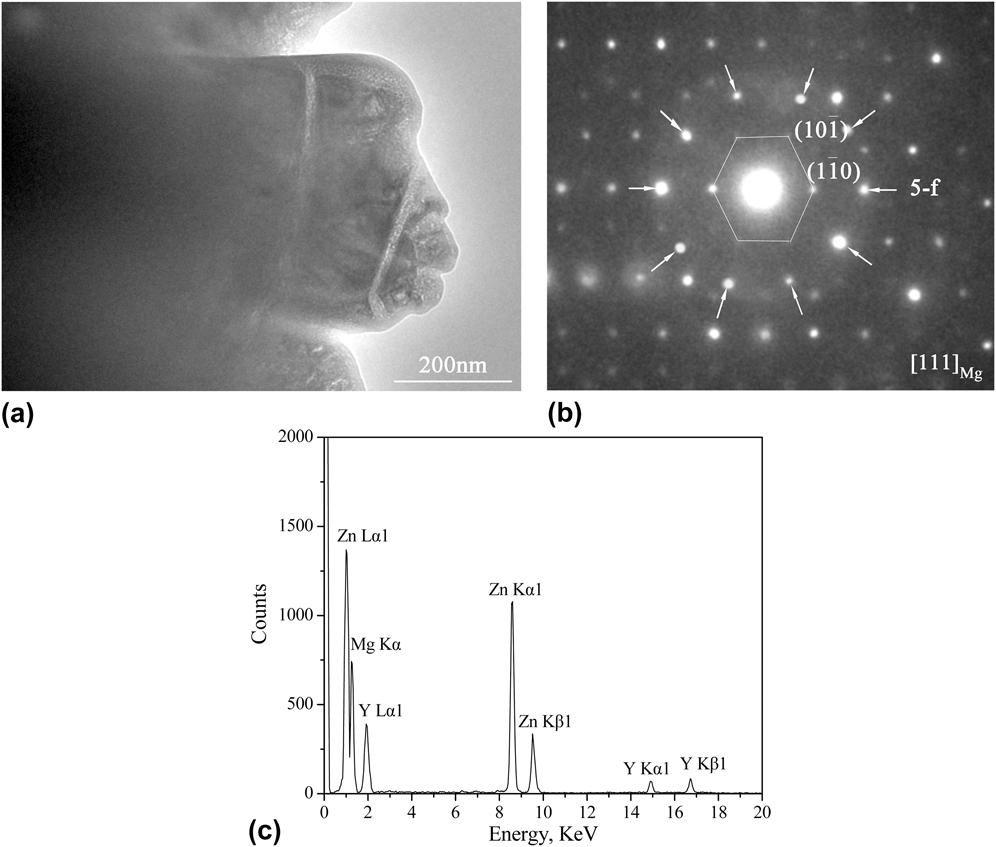
To confirm the microstructures with composition near to Mg30Zn60Y10, HRTEM analysis was carried out. Choosing either sample for the HRTEM analysis is rational, since the compositions of the ternary phases in two samples are nearly the same. Figure 3 shows the bright-field HRTEM image and corresponding selected-area electron diffraction patterns obtained from sample 1. Figure 3(b) shows a composite selected area electron diffraction patterns along the matrix hexagonal [111] axis (marked with a hexagon): the 5-fold axes marked by arrows. The I-phase can be strongly confirmed according to the result of 5-fold axes. Figure 3(c) shows the EDS of the bright-field HRTEM images, which is analyzed to be Mg31.3Zn59.3Y9.4.
(a) A bright-field HRTEM micrograph of the I-phase, (b) a composite selected area electron diffraction patterns along the matrix hexagonal [111] zone axis (marked with a hexagon), 5-fold axes marked by arrows, and (c) EDS analysis in HRTEM.
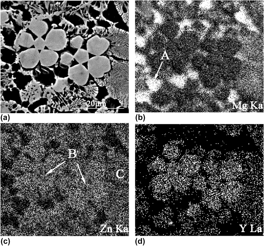
The developed lamellar eutectic structures consist of the α-Mg and I-phases [Fig. 2(a)]. Yi et al.Reference Yi, Park, Ok, Kim and Kim21 also reported this similar structure in the as-cast Mg72Zn26.5Y1.5 alloy. It indicated that the (I-phase + α-Mg) two-phase field should exist in the Mg–Zn–Y ternary alloy system. They also confirmed that a pseudobinary eutectic point between α-Mg and the ternary I-phases could exist very near to the (I-phase + α-Mg) two-phase field. So the (I-phase + α-Mg) two-phase microstructure can be easily obtained via controlling the alloy compositions as well as the cooling rate. Figure 4 gives the back-scattered electron image (BEI) and x-ray elemental maps covering the immediate neighborhood of the primary I-phase particles of the Mg63.5Zn34Y2.5 alloy. It shows that trace amounts of the Zn element are in the Mg matrix [indicated as “A”, Figs. 4(b)–4(d)], i.e., forming the α-Mg phase. However, there is hardly any Y element in the Mg matrix due to the Y atom having very limited solid solubility in Mg or Zn atoms. Figure 4(c) shows that the Zn content in the primary petal-like I-phase (indicated as “B”) and (I-phase + α-Mg) eutectic structures (indicated as “C”) are almost the same. Moreover, the primary I-phase and the (I-phase + α-Mg) eutectic structures are rich in Zn and Y elements [Figs. 4(c) and 4(d)]. It is obvious that the Y content is slightly higher in the primary I-phase particles [Fig. 4(d)], which is consistent with the EDS discussion in SEM. This difference in the composition may be related to the growth mechanism of the I-phase during the solidification process.
X-ray elemental maps around the primary I-phase using Mg Kα, Zn Kα, and Y Lα peaks, respectively. (a) BEI of the Mg63.5Zn34Y2.5 alloy, (b) Mg map, (c) Zn map, and (d) Y map.
IV. GROWTH MECHANISM OF THE ICOSAHEDRAL QUASICRYSTAL IN THE Mg63.5Zn34Y2.5 ALLOY
No matter in sample 1 or sample 2, there always exhibits a common character of 5-fold axes symmetry. Including the (I-phase + α-Mg) eutectic structures, the growth direction is also along the branches of the primary I-phase. It indicates that a special relationship between the structure of the quasicrystal and growth mechanism should exist.
In Fig. 2(a), most of the primary I-phases have a pentagonal core, and five branches form along the direction of the pentagonal corner. Likewise, as shown in Fig. 2(b), the bright quasicrystal particles distribute in a radial direction from a pentagonal core, and the intersection angle of the adjacent radial directions is ∼72°. It is just the intersection angle of the adjacent of the 5-fold rotational symmetry direction. This is extremely related to the icosahedral atomic structure. The quasiperiodicity may influence the atomic growth mechanism, and the morphology depends on the nature of the quasiperiodic potential. Since the quasicrystal can be regarded as a periodic crystal with infinite periodicity,Reference Lngersent and Steinhardt22 the roughening transition temperature should be infinity. Actually, it indicates that the quasicrystal is expected to have faceted growth. Dubost et al.Reference Dubost, Lang, Tanaka, Sainfort and Audier23 first confirmed that the slowly grown equilibrium quasicrystals in the Al–Cu–Li alloy showed pronounced facets in the growth form. This growth morphology also occurs in the Zn–Mg–RE quasicrystal alloys,Reference Tsai, Niikura, Inoue, Masumoto, Nishida, Tsuda and Tanaka24 i.e., it is a common character in quasicrystals. Attributing to this faceted growth manner, the special growth morphology reflects the point group symmetry of the I-phase and one often observes petal-like growth morphology. Figure 5(b) shows a typical five petal-like I-phase, which is the microcharacteristic of the relationship between the growth of the I-phase and the point group symmetry structure. A fast growth along 5-fold directions can lead to an icosahedron, since the vertices in an icosahedral quasicrystal are 5-fold symmetry [as shown in Fig. 5(c)]. However, if the growth front is planar, the growth morphology will look like a pentagonal dodecahedron (truncated icosahedron), which coincides with the solidification direction. Meanwhile, the Y element will be concentrated along 5-fold directions caused by fast growth. Therefore, twinning of the icosahedral quasicrystals is observed to occur along one 5-fold axis, such as “A” and “B” in Fig. 5(b). Shechtman et al.Reference Shechtman, Blech, Gratias and Cahn3 presented that the neighbor coordination icosahedrons shared by edges. This coordination is just along the 5-fold axes of the I-phase, which was confirmed by Garg and LevineReference Garg and Levine25 using the Penrose pattern of gold-rhombic blocks. Practically, these previous investigations have shown that the atoms are most closely packed along the 5-fold axes, followed by 2-fold axes.Reference Chattopadhyay, Ravishankar and Goswami26 It is concluded that the 5-fold and 2-fold axes are the preferred growth orientations of the I-phase, and the 5-fold axis is the fastest growth direction. Due to this fact, the icosahedral quasicrystal should grow in its best preferred growth orientation along each 5-fold symmetry axis. The fastest growth directions along 5-fold axes are directions of neighbor icosahedron coordination, while the lowest growth rate for the emergent lateral sides (perpendicular to 2-fold) in a facet manner [Fig. 5(b)]. These results lead to evolving into petal-like morphology finally. Similarly, the ledge growth direction along 10-fold is fastest and slowest along the 2-fold direction of the decagonal quasicrystalline phase in the Al72Ni12Co16 alloy was reported.Reference Liu, Yang, Zhou, Wang, Xu and Xu27
(a) A magnified SEM image of sample 1, for showing a more clearer growth morphology; (b) a typical SEM image of the five petal-like icosahedral quasicrystal, the core and surrounding petal marked as “A” and “B”, respectively. (c) An icosahedron model, 5-fold axes along the vertices; 2-fold axes perpendicular to the edges.
Compared to crystals, the quasiperiodicity does not seem to cause distinct difference in the growth behavior. The quasicrystalline phase acts like other crystalline phases in phase diagrams. Therefore, the primary and eutectic growths in quasicrystals can also be observed. As for the formation and the growth processes of petal-like morphology, there are two stages that are very similar to the classical crystal nucleation and growth theories. Firstly, the pentagonal core forms from the melt as the icosahedral quasicrystal morphology in the region of the Y concentration. Subsequently, each branch grows fastest along one 5-fold axis by the movement of steps, and each emergent lateral side of icosahedral grows in a facet manner at a lower rate. The planes perpendicular to 5-fold and 2-fold axes have low surface energy,Reference Chattopadhyay, Ravishankar and Goswami26 which is the dominant factor to the petal-like and polyhedral morphologies. Due to the Y concentration along 5-fold directions at the solid/liquid interface, constitutional supercooling may be caused. As a result, the planar growth is gradually replaced by cellular growth. Moreover, by taking account of the surface energy, the sharp edges and corners may get rounded and smooth after the formation of the I-phase, which can lead to the characteristic of sharp facets disappearing. Therefore, it can be seen that five branches of the primary I-phase always show cellular morphology rather than the sharp facet at the solid/liquid interface.
Because all the faceted crystals can undergo a dynamic roughening below a critical supercooling of the melt, the primary I-phase has a continuous growth and yields a smooth surface. Especially, the sharp edges and corners get coarsened and even rounded during the growth process. When the formation of the primary I-phase is almost completed, the Y content has decreased progressively in a radial direction (from the primary I-phase to the matrix phases).
The equilibrium shape of a crystal is determined by the surface energy principle and kinetics of the growth.Reference Burton, Cabrera and Frank28 Development of the microstructure and its orientation relationship are related to the solidification process. As shown in Fig. 2(a), the microstructure is divided into many parts, which take the I-phase particles as cores. Distinct boundaries between eutectic structures and the α-Mg matrix can be observed. The leafy quasicrystal eutectic structures are distributed along a radial direction from the edges of primary I-phases. There are few remaining Y elements in the supercooling liquid, because the small degree of supercooling leads to a low nucleation rate. Therefore, the composition of remaining liquid may fall into the eutectic area after the primary I-phase forming, which causes the (I-phase + α-Mg) eutectic structures form. As discussed above, there exists an orientation relationship of 5-fold//[111]Mg. It indicates that (I-phase + α-Mg) eutectic structures grow in a lamellar manner contributing to reducing the interface energy. The growth process of (α-Mg + I-phase) eutectic structures is controlled by diffusion kinetics, i.e., it is dominated by solute diffusion (especially for the Y atom). Therefore, the lamellar (α-Mg + I-phase) eutectic structures form from the remaining liquid with lower Y content. The higher cooling rate can contribute to a high nucleation rate, and results in almost of the Y element participating in the nucleation. Therefore, in sample 2, there are only uncoarsened primary I-phase grains in the matrix rather than I-phase eutectic. The primary I-phases grow into dendritic morphology along the direction of the center petal-like I-phases. Just as the arrows indicated in Fig. 2(b), it is one of the typical characters. This character is very similar to that described in Fig. 2(a).
Although the cooling rates of two samples are different, the microstructures in them reveal that the primary petal-like I-phases can precipitate directly from the melt. This formation of the I-phase is very different from the most common reports, which show that the I-phase usually forms by peritectic reactions (L + (Zn, Mg)5Y → I-phaseReference Li and Kuo29 or L + W-phase → I-phaseReference Ok, Kim, Yi, Kim and Kim30). Icosahedral short-range order (ISRO) exists widely in melts, which is incompatible with the translational periodicity of crystalline solids.Reference Frank31 Recent studies have confirmed that the ISRO can contribute to forming quasicrystalline phases.Reference Klein, Audier, Simonet, Hippert and Bellissent32–Reference Roik, Galushko, Samsonnikov, Kazimirov and Sokolskii34 It is postulated that the randomly oriented icosahedral clusters exist in the Mg–Zn–Y alloy melts, but structures in liquid Mg alloys need a further study. At the beginning of the solidification, the icosahedral short- or medium-range orders are densely packed with the action of the Y element and form icosahedral quasiperiodic structures. This can be regarded as the start of the nucleation process of the I-phase. In addition, the Y element plays a significant role in the formation and growth of the I-phase during the whole process. However, the detailed coordination models among the icosahedral clusters in the melt and their heredities from liquid to solid require a further investigation.
A. Solute partitioning during solidification
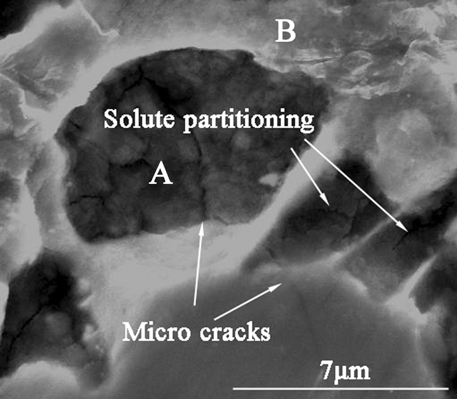
Figure 6 shows a typical enlarged image at the edge of the primary I-phase in sample 1. It is deduced that the microcrack and solute partitioning occur at the solid/liquid interface during the solidification process. The formation of cracks and separations is closely related to the cooling rate. As a result, it is only observed in sample 1 prepared under a slow cooling rate.
A typical SEM image showing the microcrack and solute partitioning around the primary I-phase.
The preferable directions along 5-fold axes lead to the Y concentration at the solid/liquid interface. The diffusion rate of the Y atom is much smaller than that of Zn and Mg atoms in liquid. If the cooling rate is low, the enrichment of the solute element Y will aggravate. Due to the difference in diffusion rates of atoms and enrichment of the solute element Y, solute partitioning takes place at the solid/liquid interface. Thus, the partition among the molten pools is the Y concentration, while the Mg concentration increases in the pools and ahead of the solid/liquid interface. It indicates that the liquid around the primary I-phase is greatly microheterogeneous. Moreover, EDS analysis shows that the composition of region “A” is Mg–25.7at.% Zn, which indicates that the solidification temperature is below 400 °C according to the Mg–Y phase diagram. Our previous work shows that it is far below the solidification temperature of the I-phase, about 430 °C.Reference Geng, Teng, Zhou and Zhao35 It is concluded that region “A” is still liquid after region “B” solidify. Therefore, it is deduced that the solute partitioning occur(s) at the solid/liquid interface during the solidification process.
As a result, the remaining liquid is divided into small molten pools by the lamellar I-phase. Then, the remaining liquid is sealed in these molten pools, which lead to the thermal stress concentration in these areas. On the other hand, the volumes of these pools certainly will shrink after the liquid solidifies finally. This is the main reason for producing microshrinkage cavities and cracks (Fig. 6) in the final stage of solidification. The growth front (perpendicular to the 5-fold directions) is essentially planar. However, due to the local compositional change at the solid/liquid interface, the planar growth is replaced by cellular growth. Thus, the solid/liquid interface, which gets originally stable or unstable, has broken down due to a change in the solidification rate and the composition. Although the solute partitioning is not observed in sample 2, the growth manner of the primary I-phase is as same as that in sample 1. Moreover, the unstable interface also occurs at the solid/liquid interface, which is mainly caused by the different growth rates within a local region. This analysis is also in good agreement with the observation of broken petals in the microstructure as shown in Fig. 2.
Moreover, attributing to the local compositional change, it is hard to avoid high degree of phason strain existing in the I-phase.Reference Tsai, Inoue and Masumoto36,Reference Ohhashi, Abe, Tanaka and Tsai37 Accordingly, the microscopic stress and defect certainly will increase the fragility of the quasicrystal. Therefore, proper control of the cooling rate can reduce defects and obtain better microstructures.
V. CONCLUSIONS
Icosahedral quasicrystals are successfully prepared under different cooling rates. Both two samples reveal that the I-phase can precipitate directly from the melt during the solidification process. As the cooling rate is relatively slow, there is more Y element in the remaining liquid after the formation of the primary I-phase. It leads to the formation of the I-phase eutectic structure whose Y content is slightly lower than that in the primary I-phase. Almost all the Y element is exhausted after the formation of the I-phase.
The preferred growth directions of the I-phase are along their 5-fold axes, and the planes perpendicular to the 5-fold axes grow in a facet manner. Under a relatively slow cooling rate, solute partitioning often occurs at the solid/liquid interface, which causes that the partial remaining liquid is sealed in these molten pools. Therefore, the thermal stress concentration, microshrinkage cavity, and crack defects may occur in these regions.
ACKNOWLEDGMENTS
This work is supported by the National Natural Science Foundation of China [Grant No. 51301076] and the Special Joint Funds of Natural Science Foundation of Shandong Province, China [ZR2013EML004].