I. INTRODUCTION
Magnetoelectric (ME) materials, which can display an induction of magnetization by an electric field or of polarization by a magnetic field, have stimulated tremendous fundamental and practical interests due to their potential applications in multifunctional devices such as sensors, actuators, and transducers.Reference Fetisov, Bush, Kamentsev, Ostashchenko and Srinivasan1–Reference Srinivasan4 In the past decades, ME materials have been developed in single-phase materials and multiphase bulk composites. Single-phase ME materials are not suitable for practical applications owing to their weak ME response and low working temperature.Reference Folen, Rado and Stalder5 Bulk ME composites, especially layered ME composites made by combining magnetostrictive and piezoelectric layers, exhibit excellent ME effect at room temperature. To enhance the ME voltage coefficient, layered ME composites, with Ni, Fe-Co alloys, or rare-earth alloys as the magnetostrictive phase and with lead zirconate titanate (PZT), lead magnesium niobate-lead titanate as the piezoelectric phase, have been made into various structures.Reference Ma, Shi and Nan6–Reference Pan, Bai, Volinsky, Chu and Qiao14
The ME effect in layered ME composites is a product property of the magnetostrictive and piezoelectric effects. A magnetic field applied to the layered ME composites will induce strain in the magnetostrictive layer which is passed along to the piezoelectric layer, where it induces an electric polarization.Reference Nan15 The ME coupling of layered ME composites mainly arises from the magnetic–mechanical–electric transform through the stress-mediated transfer in the interface. Therefore, the interfacial coupling is the key to the ME coupling of layered composites. However, in practice, there is no ideal interface for layered ME composites, which reduces the ME coupling.Reference Nan, Bichurin, Dong, Viehland and Srinivasan16
Besides utilizing the product property of magnetostrictive and piezoelectric effects mentioned above, the extrinsic ME effect can also be realized in multiphase magnet-piezoelectric composites using the direct coupling of the magnetic attractive/repellent force effect in the magnet phase with the piezoelectric effect in the piezoelectric phase, which is not influenced by interface condition.Reference Jia, Or, Lam, Chan, Tang, Zhao and Luo17–Reference Leung, Or, Zhang and Ho20 In this work, we report a large ME coupling obtained from a very simple bi-rectangular structure made up of epoxy-bonded negative/positive magnetostrictive and piezoelectric flakes.
II. EXPERIMENTAL
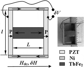
The bi-rectangular ME composite structure of negative/positive magnetostrictive and piezoelectric flakes is shown illustratively in Fig. 1. The commercial PZT flakes used in this work were sliced with various dimensions of 8 × 6 × 0.7, 10 × 6 × 0.7, 15 × 6 × 0.7, and 18 × 6 × 0.7 mm3 (l × w × t). It was polarized along the thickness direction and its dielectric, piezoelectric, and electromechanical coupling coefficients were ε 33 = 2400, d 33 = 400 pC N−1, and k 33 = 0.70, respectively. The TbFe2 flakes were prepared by arc melting under argon atmosphere. Its dimensions were 6 × 6 × 2.5, 8 × 6 × 2.5, 10 × 6 × 2.5, and 12 × 6 × 2.5 mm3 (l × w × t), respectively. The commercial Ni flakes were sliced with various dimensions of 8 × 6 × 0.1, 10 × 6 × 0.11, 12 × 6 × 0.1, and 14 × 6 × 0.1 mm3 (l × w × t). The TbFe2 and PZT flakes were bonded by using silver epoxy. The Ni and PZT flakes were not connected electrically by using epoxy.
Schematic illustration and photograph of a bi-rectangular magnetoelectric (ME) composite structure of negative/positive magnetostrictive and piezoelectric flakes.

In this case, the interface between magnetostrictive and piezoelectric phases is not required to achieve ME coupling. The working principle of the bi-rectangular ME composite structure is as follows. When an external ac magnetic field (H ac) is applied along the length direction of magnetostrictive flakes (Ni and TbFe2 flakes), the TbFe2 flake will produce an extensional strain while the Ni flakes will produce a shrinkage strain because of the difference in magnetostrictive properties of each flake. These strains then transfer to the central and end parts of the PZT flakes. Due to the piezoelectric effect, the PZT flakes will induce a charge output.
The ME effect of the proposed structure was measured by applying both constant (H dc) and alternating (δH) magnetic fields parallel to the length direction of TbFe2 flakes. The induced voltage signal δV across the sample was amplified and measured by an oscilloscope.Reference Bi, Wang, Pan and Wu8 The ME voltage coefficient was calculated based on α E = δV/(t PZTδH), where t PZT is the thickness of PZT flakes. In our experiment, δH = 1.2 Oe as the amplitude of the AC current through the coil is equal to 1 A.
III. RESULTS AND DISCUSSION
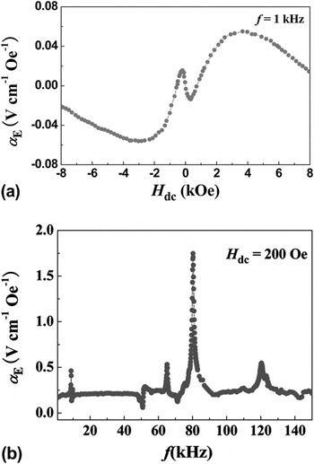
Figure 2(a) shows the bias magnetic field (H dc) dependence of ME voltage coefficient (α E) for the bi-rectangular ME composite structure. The measurements were carried out at f =1 kHz. The lengths of the TbFe2 and PZT flakes (L and l) are 6 and 10 mm, respectively. Data are shown for both increasing and decreasing H dc. On increasing H dc from zero, it is seen that α E decreases until a minimum value is reached at a certain H dc and then increases subsequently. With further increase in H dc, α E reaches a maximum value around H dc = 3.5 kOe and then decreases subsequently. The measurements on the ac magnetic field frequency (f) dependence of the ME coupling are also performed. For such studies, the bias magnetic field H dc was set at 200 Oe and α E was measured as f was varied from 1 to 150 kHz. As shown in Fig. 2(b), one observes that there are four obvious resonance peaks which are related to the electromechanical resonance.Reference Bichurin, Filippov, Petrov, Laletsin, Paddubnaya and Srinivasan9 And a maximum ME voltage coefficient α E = 1.8 V cm−1 Oe−1 can be obtained at resonance frequency of f r = 80.2 kHz. The maximum ME voltage coefficient α E observed here is much larger than that of layered ME Ni/PZT/Ni, TbFe2/PZT/TbFe2, and Ni/PZT/TbFe2 composites with the same Ni, TbFe2, and PZT reported in Ref. Reference Bi, Wang, Pan and Wu8, which indicates that the proposed structure is more efficient than traditional ones.
(a) The bias magnetic field (H dc) at f =1 kHz and (b) frequency at H dc = 200 Oe dependences of ME voltage coefficient (α E) for the bi-rectangular ME composite structure with L = 6 mm and l = 10 mm.

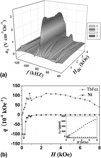
Figure 3(a) shows the three-dimensional plot of the bias magnetic field (H dc) and frequency (f) dependences of ME voltage coefficient (α E) for the bi-rectangular ME composite structure with L = 6 mm and l = 10 mm. At resonance frequency of f r = 80.2 kHz, the α E increases with H dc, up to 3.0 V cm−1 Oe−1 at H dc = 0.5 kOe, and then decreases slightly as the H dc increases until 1 kOe. With further increasing H dc from 1 to 3.5 kOe, one observes that the α E shows a nearly constant plateau behavior. But when H dc > 3.5 kOe, the α E decreases as H dc increases, which is the same as the phenomena shown in Fig. 2(a). The wide-field behavior of the maximum α E at resonance frequency, which can provide a stable electrical signal in a wide range of magnetic field, offers the possibility of making multifunctional devices from this kind of structure.
(a) Three-dimensional plot of the bias magnetic field (H dc) and frequency (f) dependences of ME voltage coefficient (α E) for the bi-rectangular ME composite structure with L = 6 mm and l = 10 mm and (b) the applied magnetic field dependence of the piezomagnetic coupling coefficient q for TbFe2 and Ni flakes. The inset shows the applied magnetic field dependence of the in-plane parallel magnetostriction λ // for TbFe2 and Ni flakes.

The values of the ME voltage coefficient α E are proportional to the piezomagnetic coupling coefficient of the magnetostrictive flake q ∼ δλ/δH,Reference Bichurin, Filippov, Petrov, Laletsin, Paddubnaya and Srinivasan9 where λ is the magnetostriction. The linear magnetostriction was measured by using a standard strain-gauge technique in directions parallel (λ //) to applied magnetic fields. The applied magnetic field (H) dependence of the piezomagnetic coupling coefficient (q) for TbFe2 and Ni flakes is shown in Fig. 3(b). The applied magnetic field dependence of the in-plane parallel magnetostriction λ // for TbFe2 and Ni flakes is also shown as an inset in Fig. 3(b). The TbFe2 flake shows a positive magnetostriction, while the Ni flake exhibits a negative magnetostriction. When H > 1 kOe, the q of Ni is equal to zero due to the magnetostriction of Ni reaches the saturation stage. But the magnetostriction of TbFe2 does not reach the saturation stage even though H = 8 kOe. For the bi-rectangular ME composite structure, when H < 1 kOe, the magnetostriction of Ni does not reach the saturation stage, both Ni and TbFe2 flakes play a role in α E, which results in a negative α E in low field [shown in Fig. 2(a)] and a largest ME voltage coefficient obtained with a certain H dc at resonance frequency. When 1 kOe < H <3.5 kOe, the magnetostriction of Ni reaches the saturation stage, TbFe2 flake plays a predominant role in α E. The q of TbFe2 flake increases as H increases. Hence, the α E increases slowly until a maximum value is reached [shown in Fig. 2(a)]. When H > 3.5 kOe, the q of TbFe2 flake decreases as H increases, so the α E decreases. In the last two processes, α E shows a nearly plateau behavior at resonance frequency.
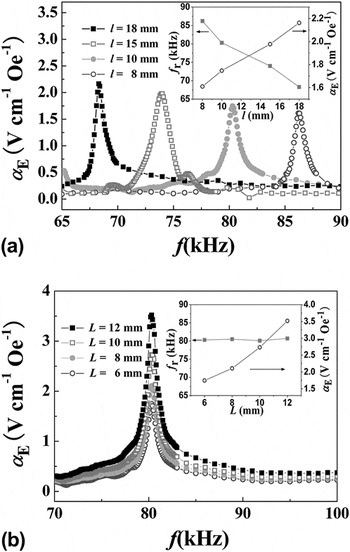
For layered ME composites, the resonance frequency is strongly influenced by the length of piezoelectric layer, f ∝ 1/l.Reference Bi, Wang, Pan and Wu8 The resonance frequency decreases as the length of piezoelectric layer increases. Figure 4(a) shows the frequency (f) dependence of the ME voltage coefficient (α E) with various length (l) of PZT flakes. One observes that the α E and resonance frequency (f r) depend strongly on l. With the increasing in l from 8 to 18 mm, the f r of the bi-rectangular ME composite structure gradually decreases from 86.2 to 68.3 kHz, while the maximum α E of the composite structure increases from 1.61 to 2.16 V cm−1 Oe−1, which is also shown as an inset in Fig. 4(a). The experimental result is in good agreement with the theoretical prediction. The dependence of the α E on f with various lengths (L) of TbFe2 flakes is shown in Fig. 4(b). The L dependence of the f r and the maximum α E is also shown as an inset in Fig. 4(b). It can be seen that the value of the maximum α E increases with L, which can be ascribed to the increasing magnetostriction due to shape demagnetization effect.Reference Srinivasan, De Vreugd, Laletin, Paddubnaya, Bichurin, Petrov and Filippov21 The resonance frequency is not affected by L, which is attributed to the bi-rectangular structure. Obviously, if the length of PZT and TbFe2 flakes (l and L) is increased, higher values of ME voltage coefficient would be obtained.
(a) Frequency (f) dependence of the ME voltage coefficient (α E) with various l for the bi-rectangular ME composite structure. The inset shows the l dependence of the f r and the maximum α E. (b) f dependence of the α E with various L. The inset shows the L dependence of the f r and the maximum α E.

IV. CONCLUSIONS
In summary, a large ME coupling has been obtained from a very simple bi-rectangular structure. The experimental results have demonstrated that the ME effect is affected by negative and positive magnetostrictive flakes, which is different from that of other ME structures. At resonance frequency of f r = 80.2 kHz, the α E shows a nearly constant plateau behavior with H dc increased from 1 to 3.5 kOe, which is believed to be useful for future device application. The resonance frequency of the bi-rectangular ME composite structure gradually decreases as the length of PZT flakes increases. The maximum ME voltage coefficient increases with the length of PZT or/and TbFe2 flakes. The outstanding advantage of the proposed structure is that there is no interface between magnetostrictive and piezoelectric flakes required to achieve ME coupling, which provides a new choice to make ME devices.
ACKNOWLEDGMENTS
This work is supported by the National Natural Science Foundation of China under Grant No. 11174148 and the Natural Science Foundation of Jiangsu Province of China (Grant No. BK2010505) and the Funding of Jiangsu Innovation Program for Graduate Education (Grant No. CX10B_099Z). D.A. Pan would like to acknowledge support from the National Natural Science Foundation of China under Grant 50802008.