1. INTRODUCTION
The current navigation market is clearly dominated by the Global Positioning System (GPS). This is especially true in land-vehicle navigation (LVN) applications. For most LVN systems GPS receivers are the primary source for providing the vehicle navigation information which includes time, position and velocity with high accuracy. Cycle slips caused by loss of lock between the receiver and a satellite are one of the limitations of GPS. These cycle slips can significantly degrade the positioning accuracy in kinematic applications. Hence, GPS can only provide precise information in ideal conditions such as an open sky environment. Therefore, the GPS does not work very well in urban areas with overhead canopies due to frequent signal blockage occurrence and signal attenuation that deteriorates the obtainable positioning and navigation accuracy. For the moment, urban applications that require continuous position determination (e.g. LVN) cannot depend solely on GPS. On the contrary, some LVN applications also require the vehicle attitude which GPS cannot provide except when a multi-antenna system is used. Even then, such a system will not necessarily provide accurate attitude angles.
Thus, as a solution for these GPS limitations, GPS is integrated with other systems that can provide navigation during GPS signal blockage periods (i.e. bridging GPS outages) and can also provide other required information that cannot be obtained using GPS alone (i.e. attitude). The most commonly used system for integration with GPS is an Inertial Navigation System (INS). This is due to the fact that both navigation systems are complimentary and their integration overcomes their individual limitations. In INS/GPS integration, the GPS provides time, position and velocity while the INS provides attitude information. In addition, the INS can provide very accurate position and velocity with a high data rate between GPS measurement fixes. Therefore, INS is used to detect and correct GPS cycle slips and is also used for navigation during periods of GPS signal loss of lock. Finally, the GPS can aid in-motion calibration of the INS accelerometer and gyro sensors errors.
For several years, the integration of high or medium quality INS with GPS has been implemented for accurate LVN. However, these grades of inertial systems are limited by their significant size and high cost ($25,000–$150,000). In addition, with the new federal access regulations, the use of such systems will be restricted and permitted only for authorized personnel. In the last decade, the demand for LVN services has grown rapidly. To meet the demand, many studies have been directed towards developing low-cost inertial systems to overcome the above-mentioned restrictions. The development of low-cost sensors, namely Micro-Electro-Mechanical Systems (MEMS), has been the most promising avenue towards a solution. Advances in MEMS technology have made it possible to produce chip-based inertial sensors that are small, lightweight, consume very little power and are extremely reliable.
Although MEMS inertial sensors reduce the cost and size of the navigation system dramatically (which are two of the primary considerations for several LVN applications), some LVN applications require even lower cost and smaller systems. The standard and most commonly used approach in this case is to choose the lowest cost and smallest GPS chip and MEMS inertial sensors for the MEMS IMU/GPS integrated system. However, a major factor, the MEMS accuracy, is often not taken carefully into consideration. This is due to the fact that the cheapest and smallest MEMS inertial sensors rarely provide the required accuracy for many LVN applications. Therefore, in this paper, another effective approach that meets the requirements of cost, size and accuracy is introduced and applied. The proposed approach is based on simplifying the six-sensor full MEMS IMU (three gyros and three accelerometers) by removing some of the inertial sensors that are less important for navigation purposes and replacing their unavailable signals by pseudo signals that have constant values plus white noise. The methodology and application of such partial MEMS IMU approaches is introduced. MEMS partial IMU data processing using standard navigation algorithms is described and performance analysis using real kinematic field data is shown and discussed.
2. PARTIAL IMU CONFIGURATIONS
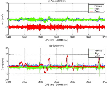
As mentioned earlier, the main concept of the proposed approach is to reduce the number of inertial sensors in the MEMS IMU integrated with GPS for LVN applications. The omitted sensors in this case should have less contribution to the navigation process. To investigate these contributions, the signals for a full MEMS IMU in a typical land-vehicle environment should be studied first. Figure 1 shows a portion of typical MEMS IMU signals obtained in a land-vehicle test. Since land-vehicles mainly run on flat roads with ramps typically less than 5 degrees, the output of the vertical (z-axis) accelerometer (the red line in Figure 1a) is composed mainly of the local gravity plus the addition of road vibrations or undulations. Thus, the z-axis accelerometer signal seems to carry little navigation information, especially for horizontal positioning. It is a known fact for LVN purposes that more interest is always given to the movement in the horizontal plane rather than the movement in the vertical direction. Therefore, the z-axis accelerometer can be excluded to save cost and size of the system.
MEMS IMU sensor signals in a typical LVN.

On the other hand, a similar analysis can be applied to the two MEMS horizontal gyros (the green and blue lines in Figure 1b). From the figure, the output of the two horizontal gyros can be regarded as zero mean white noise. Hence, both horizontal gyros contribute very little important navigation information and consequently they may be excluded from the full IMU configuration to save cost and reduce the size of the navigation system. In this case, and since MEMS gyros are more expensive than the corresponding MEMS accelerometers, it makes more sense to omit as many gyros from the IMU. From the above analyses, the minimum reduced or partial MEMS IMU configuration will consist of two horizontal accelerometers plus one vertical (heading) gyro, or simply 2A1G. However, taking into account that many of the current MEMS accelerometers available on the market are tri-axial accelerometers which are often less expensive than purchasing individual accelerometers, the other convenient partial IMU configuration will consist of three accelerometers and one vertical gyro, or simply 3A1G. Furthermore, it was indicated in some literature, such as Brandt (Reference Brandt and Gardner1998) and Mayhew (Reference Mayhew1999), that the above configurations are considered as the most popular simplified IMU configurations. The essential fact behind these simplified sensor configurations is to assume the vertical axis of the IMU is aligned to the vertical axis of the navigation frame, which is a valid assumption for land vehicles.
The conventional approach to implement these simplified MEMS sensor suites (or partial IMUs) is to develop specific inertial mechanizations and Kalman Filters (KFs) for each configuration depending on the number and orientation of the chosen sensors. In general, this approach is time-consuming and expensive (Phuyal, Reference Phuyal2004). In addition, using an available inertial navigation algorithm would not be suitable for data processing. Finally, in the case of using a simplified IMU configuration and processing using a specially designed navigation algorithm, a full navigation solution (three positions, three velocities and three attitude angles) will not be available. In the next section, a universal method to process any simplified MEMS IMU sensor configuration is introduced. The algorithm concept and implementation will be described by introducing the idea of inertial sensor pseudo signals (or pseudo sensors) that replace the unavailable signals of the non-existing sensors. In this case, the real partial IMU sensor data plus the induced signal data can be considered as a full IMU sensor data. Thus, there will be no need to use or develop a specific navigation algorithm for processing the data. Instead, standard existing algorithms will be used. Moreover, the most important strength of this method is that a full navigation solution is available. In the following, any simplified MEMS IMU will be referred to as a MEMS sensor suite.
3. METHODOLOGY
It was discussed in the previous section that two MEMS sensor suite configurations would be implemented: 2A1G and 3A1G. Recalling the vertical accelerometer signal shown earlier in Figure 1a, such signals can be approximately considered as a constant local gravity plus large white noise (bumping of the vehicle). Therefore a pseudo signal (or pseudo z-axis accelerometer whose output is always the constant gravity) can be proposed to replace the omitted vertical accelerometer in the 2A1G configuration. This signal then can be fed into the MEMS IMU/GPS navigation algorithm used for the full IMU configuration data processing. Obviously this pseudo signal has very large noise, which is related to the road disturbances and velocity of the vehicle. Thus, this should be reflected in the KF of the navigation algorithm. Moreover, the error of the pseudo signal is assumed to be Gaussian white noise, which is required by the KF. Therefore, the spectral density q accel of the pseudo signal error can be calculated using the standard deviation (STD) of the vehicle bumping acceleration and the bandwidth (BW) of the IMU, such that:
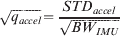
For the vertical accelerometer signal in Figure 1a, the values for the STDaccel and BWIMU are 0·35 m/s2 and 40·0 Hz, respectively. Substituting these values in Equation 1a, q accel can be obtained as:

This obtained value of q accel is used to set the relevant KF parameter, i.e. the component in the spectral density matrix that corresponds to the noise of the pseudo signal. However, it should be stressed that, as any other parameter of the KF, this parameter needs to be further tuned to get the optimal results when the pseudo signal is fed into the standard navigation algorithm. For more details about tuning the parameters of the KF, see Nassar et al. (Reference Nassar, Niu, Aggarwal and El-Sheimy2006). In the case of the proposed 2A1G or 3A1G configurations, the same pseudo signals concept can be applied for the omitted two horizontal gyros. To construct such signals, they can be considered as a constant zero mean with large white noise error. According to the gyro data shown in Figure 1b, the noise spectral densities of these two pseudo gyros q gyro can be obtained using a similar formula to 1a but by considering the gyro signals. In this case, and from Figure 1b, the value of STDgyro for both horizontal gyros is 0·50 deg/s. Thus, the q gyro value is obtained as:

On the other hand, a minor issue of this processing method is that the actual error of the pseudo signals may not be mainly white noise. In this case, other error components may mislead the KF and cause divergence of the solution especially during GPS signal outage periods. However, in the worst case scenario, the pseudo signal parameters in the KF (i.e. their corresponding components in the spectral density matrix) can be set large enough so that these pseudo signals will not take effect in the navigation algorithm. For any MEMS inertial suite integrated with GPS, the pseudo inertial signals and their spectral densities together with the other real inertial sensors and GPS signals, can be fed into any standard GPS/INS navigation software for processing as if it is a full IMU. Again, in this case, the full navigation solution (three positions, three velocities and three attitude angles) can be obtained even though some inertial sensors are omitted from the IMU.
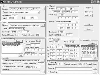
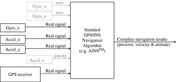
For all data processing performed in this paper, the AINS™ (Aided Inertial Navigation System) Toolbox for MatLabTM will be used. The AINS™ software was developed by the Mobile Multi-Sensor Systems (MMSS) research group at the University of Calgary (U of C). AINS™ optimally combines the data files from an IMU together with information from other aiding sensors such as GPS, odometers and heading aids. The toolbox supports various attitude parameterizations including the Direction Cosine Matrix (DCM), Euler angles, rotation vector and quaternion. Several options are available in the software to set different processing configurations, e.g. choosing different alignment modes, simulating GPS signal outages, etc. For more details about AINS™, consult Shin and El-Sheimy (Reference Shin and El-Sheimy2004). Figure 2 shows the interface of the AINS™ software while Figure 3 represents a block diagram summarizing the full structure of the proposed method.
User Interface of the AINS™ software developed by the MMSS Group.

Block diagram of the proposed method based on the pseudo signals approach. (Grey blocks represent the pseudo signals.)

4. FIELD TEST AND INSTRUMENTATION USED
To test the efficiency of the proposed approach, a land-vehicle MEMS field test was used for the analysis. The field test was conducted in Calgary in 2004 by the MMSS group at U of C in collaboration with NovAtel Inc. The test included a MEMS full IMU, two NovAtel OEM4 GPS receivers (rover and master for DGPS) as well as a high-quality IMU (Honeywell CIMU) to provide the navigation reference. In this test, the reference navigation solution for testing the MEMS IMU/GPS system is obtained from the smoothed best estimate of the CIMU/DGPS data processing provided by Applanix Corporation POSPac™ software while the MEMS IMU/GPS data was processed by the MMSS group AINS™ software. The MEMS IMU used in the field test was also developed by the MMSS group at U of C. For such an IMU, surface-micromachined (low-end) MEMS gyro and accelerometer sensors from Analog Devices Inc. (ADI) were used with a total cost of less than $100. Table 1 gives the main characteristics based on lab testing after calibration. More details about the MMSS group developed ADI MEMS IMU can be found in El-Sheimy and Niu (Reference El-Sheimy and Niu2004) and Niu and El-Sheimy (Reference Niu and El-Sheimy2005).
MMSS Group MEMS IMU characteristics after lab testing and calibration.

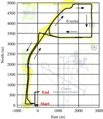
The trajectory of the field test is shown in Figure 4. The total kinematic period of the test was about 40 minutes. Since the MEMS full IMU was used in the test, all six sensor signals from the MEMS IMU were collected for the duration of the test. Considering a partial IMU configuration, the actual signals for some of the sensors (those that were to be considered as omitted sensors from the IMU) were replaced by pseudo signals as described earlier. Hence, the simplified sensor suite data is processed using the actual signals from the remaining sensors and the pseudo signals for the omitted sensors. The results of the partial IMU were then compared to the corresponding full IMU solution.
Trajectory of the IMU/GPS field test.

For the analysis, the 2A1G simplified IMU configuration results are shown as an example since the results of the 3A1G configuration showed similar characteristics. For a clear comparison between the simplified and full IMUs in terms of navigation performance, the comparison should mainly be performed in the IMU stand-alone navigation mode, i.e. during GPS signal blockage periods. Therefore, some short-term GPS signal outages (30 s each) were induced in this test by removing the GPS solution input to the KF. Sixteen GPS signal outage periods were carefully selected to cover all typical dynamics of land-vehicles. The navigation errors obtained for each processing scenario during such GPS blockage intervals were then used to evaluate the performance of the system in both cases.
5. RESULTS AND ANALYSES
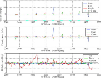
Following the test analysis procedure described in the previous Section, the full IMU navigation errors for the first eight GPS signal outages are shown in Figure 5. The average 3D position drift during the sixteen 30 s GPS signal outage periods was 28·3 m. The corresponding attitude errors were 0·20 deg (RMS) for pitch and roll and 1·20 deg (RMS) for the heading. These results represent the typical performance of a MEMS IMU/GPS navigation system and will be used as a baseline to investigate the 2A1G sensor suite results.
Navigation errors using the full IMU/GPS during 30 s GPS signal outages.

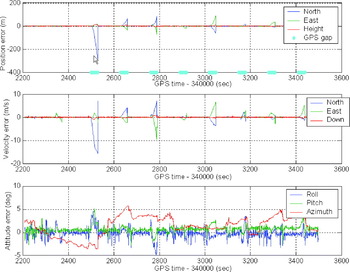
By considering only the two horizontal accelerometers and the vertical gyro signals (2A1G), the proposed pseudo signal method was used to generate the output of the other three omitted sensors. All six sensor signals (real and generated) were then fed into the AINS™ software with the corresponding modifications to the KF parameters. The corresponding navigation errors of the 2A1G partial IMU configuration for the first eight GPS signal outages are shown in Figure 6. In this case, the average 3D position drift during the sixteen 30 s GPS signal outages was 67·7 m. Although it is about two times larger than the corresponding full IMU position errors, this level of accuracy is not out of expectation for the 2A1G configuration and can be accepted by many applications. The attitude errors degraded to the level of 1·0 deg (RMS) for pitch and roll, and 2·5 deg (RMS) for the heading. Table 2 summarizes the results obtained from the full IMU and 2A1G sensor suite.
Navigation errors using the 2A1G sensor suite/GPS during 30 s GPS signal outage.

Comparison of navigation errors with full IMU and 2A1G sensor suite during GPS signal outages.

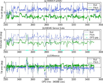
By investigating the 2A1G error behaviour in Figure 6, the tilt error (pitch and roll) degraded significantly compared to the full IMU case (Figure 5). Obviously, this is due to the removal of the two horizontal (pitch and roll) gyros. Figure 7 compares the tilt errors of the full IMU and the 2A1G sensor suite. Figure 7a represents the true tilt angles (i.e. related to the full IMU), Figure 7b shows the tilt angles estimated in case of the 2A1G sensor suite and Figure 7c gives the tilt angle error degradation due to simplifying the IMU. It should be noted here that from Figure 7b, the pitch and roll can be estimated indirectly using the GPS position updates, during GPS availability. In this case, the estimated roll and pitch angles are very close to the true values. However, when GPS signals are blocked, the 2A1G tilt angle estimation cannot be updated from GPS for accurate measurements due to the absence of the horizontal gyros. Therefore, the 2A1G pitch and roll angles tend to stay constant during the GPS outage period. On the other hand, the actual tilt angles in case of the full IMU continually change in reality, and hence, the 2A1G tilt error becomes large during GPS signal outages. This in turns causes larger position drifts in the north and east directions (see Figure 6). Some of the typical cases for the above discussion are GPS signal outages #1, #3 and #5 where the actual tilt angles changed significantly and this caused large position drifts due to the removal of the horizontal gyros in the partial IMU configuration. On average, the induced position drifts during 30 sec GPS outages can be approximately estimated by the tilt variation of the vehicle in mission. See Figure 7a, the standard deviation of the pitch and roll angles is 1·06 deg, which represents the average level of the tilt change. Since the partial IMU cannot follow any tilt change during GPS outages, it will have 1·06 deg tilt error on average, which will cause position error in GPS outages:
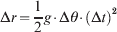
where: g is the gravity at 9·81 m/s2; Δθ is the average tilt error during the GPS outage, at 1·06 deg, i.e. 0·0175 rad; Δt is the length of the GPS outage, 30 sec; and Δr is the position drift at the end of the GPS outage. Substituting these known inputs into equation (2), the position drift, Δr, in the outage should be about 77·4 m.
Tilt angles estimation using full IMU and 2A1G configuration.

Recall Table 2, the actual position drifts of the partial IMU after 30 sec GPS outages are 67·7 m on average, which is close to the derived position drift caused by the tilt error (77·4 m). It shows that the missing horizontal gyros, which cause the tilt error in GPS signal outages, are the major reason of the increased position drift. It also confirms that the proposed method of processing the partial IMU gives a reasonable result since it meets the theoretical analysis for the error source.
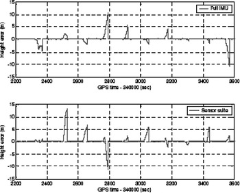
Due to the absence of the vertical accelerometer in the 2A1G configuration, the height accuracy is expected to be worse than the full IMU especially during GPS signal outages. Figure 8 compares the height drifts of the full IMU and the 2A1G sensor suite during the first eight 30 s GPS signal outages. The figure shows height accuracy degradation for the 2A1G sensor suite compared with the full IMU. In this case, the average height drift during the sixteen 30 s GPS signal outages increased from 3·0 m for the full IMU to 4·6 m for the 2A1G sensor suite; this was expected due to the removal of the vertical accelerometer.
Height errors during 30 s GPS signal outages using full IMU and 2A1G sensor suite configuration.

Finally, it should be stressed that although there are no horizontal gyros to provide information for estimating the pitch and roll in the 2A1G sensor suite, the proposed method can make use of the GPS position updates to estimate the tilt angles indirectly. This is an additional advantage of this method compared to the other conventional methods that are based on a navigation algorithm designed specifically for the actual number of sensors used (i.e. three sensors in the 2A1G configuration). In this case, the conventional methods either assume no tilt angles or use the accelerometers to measure the inclination using the static assumption, which usually leads to large errors compared to those obtained using the proposed method. According to the results and analyses shown and discussed, the proposed universal method for processing any MEMS partial IMU configuration proved to work very well. The results obtained for the simplified IMU in terms of navigation performance are within the expected levels and demonstrate the major advantages of the proposed approach.
6. SUMMARY AND CONCLUSIONS
In this paper, a universal approach for processing any simplified MEMS inertial sensor configuration when integrated with GPS for land-vehicle navigation was proposed. The new approach is based on introducing MEMS inertial sensor pseudo signals. For any MEMS inertial sensor configuration that is not a full IMU consisting of three gyros and three accelerometers, the pseudo signals are considered for the MEMS sensors missing from the full IMU configuration. In this case, any MEMS inertial sensor or partial IMU configuration can be processed using the standard IMU/GPS navigation algorithms as a full IMU. Consequently, there is no need to develop or design a particular navigation algorithm for each specific MEMS suite configuration. By tuning the Kalman filter parameters of the navigation algorithm that correspond to the sensor pseudo signals appropriately, the existing sensor signals and the induced sensor signals are processed effectively to estimate the navigation information.
The validity of this method was verified by selecting a typical MEMS inertial sensor suite configuration that consisted of only three sensors: one heading gyro plus two horizontal accelerometers. This configuration was compared to the full IMU configuration in terms of inertial/GPS navigation accuracy and also inertial stand-alone performance during GPS signal outage periods using real kinematic field MEMS IMU/GPS data. The results showed that when GPS is available the navigation performance of the inertial/GPS is similar for both the sensor suite and full IMU configurations. For the inertial stand-alone performance during 30 second GPS signal outages, the navigation errors of the inertial sensor suite were twice as large as the corresponding full IMU errors in terms of position and heading. This is the expected performance level for a simplified three-sensor inertial MEMS setup.
For a simplified MEMS inertial suite, and compared to the traditional methods that have to develop specific inertial mechanization and Kalman filtering for a certain sensor configuration, the proposed method in this paper has two major advantages. The first is that it does not need to develop new navigation algorithms for specific or different sensor configurations. For any selected inertial sensor suite, only pseudo signals need to be constructed and fed into the standard full IMU/GPS navigation algorithm; this is easier and saves time and cost. The second advantage is that the new approach can provide the full navigation information, including position, velocity and attitude although some inertial sensors are absent. In other common methods, this is not available where the assumption of zero tilt angles is usually made or an estimation is performed using accelerometer measurements in static mode. To further promote this proposed approach, other MEMS inertial sensor configurations should be investigated and more pseudo signal models should be designed.
ACKNOWLEDGEMENTS
This study was supported in part by research funds from the Natural Science and Engineering Research Council of Canada (NSERC) and the Canadian Geomatics for Informed Decisions (GEOIDE) Network of Centers of Excellence (NCE) to Dr. Naser El-Sheimy. Dr. Eun-Hwan Shin is acknowledged as a co-author of the AINS™ toolbox used in this paper. NovAtel Inc., Calgary is acknowledged for the cooperation in the performed field test used for the analysis.