I. INTRODUCTION
Super wideband (SWB) covers both short-range and long-range transmission which includes the ultra wideband (UWB). SWB covers the super high frequency range from 3 to 30 GHz which is more than the UWB range. UWB was approved by the Federal Communications Commission for unlicensed operation in the 3.1–10.6 GHz band [1].
The prime issue in SWB communication systems is the design of a compact antenna providing SWB characteristics. In this regard, a number of planar monopoles with different structures have been reported for UWB. The literature [Reference Liang, Zhong and Wang2–Reference Yildirim, Cetiner, Roqueta and Jofre12] has extended their study to enhance characteristics of compactness, omnidirectional radiation pattern, and wideband characteristics. Only a limited number of SWB antennas have been reported in the literature [Reference Liang, Zhong and Wang2–Reference Yan, Zhong and Liang7, Reference Chen, Sim and Row13–Reference Azari16] and SWB antennas provide a wider and longer range communication which is required for efficient communication in the near future. Due to the short range communication characteristics of UWB antennas, the SWB antennas will be a good candidate for different communication applications [Reference Chen, Sim and Row13]. A restructured tapered ground plane using a top-loaded notched radiating element design is discussed in [Reference Deng, Xie and Li3]. Other simple structured SWB antenna designs such as the circular [Reference Liang, Zhong and Wang2] and near-elliptical monopole antenna [Reference Dong, Hong, Liu, Zhang and Kuai4] are investigated. Although the elliptical [Reference Angelopoulos, Anastopoulos, Kaklamani, Alexandridis, Lazarakis and Dang5] and printed slot planar inverted cone antennas [Reference Cheng, Hallbjörner and Rydberg6] design are also able to satisfy the SWB requirement, their corresponding electrical dimensions are 0.38λ × 0.38λ and 0.41λ × 0.41λ. Here, the wavelength λ refers to the lower-end frequency that meets the 10 dB return loss. Several antennas have been reported with lower band edge frequencies greater than 2 GHz [Reference Deng, Xie and Li3, Reference Cheng, Hallbjörner and Rydberg6, Reference Cao, Huang, Zhang and Alrawashdeh14–Reference Srifi, El Mrabet, Falcone, Ayza and Essaaidi17]. The proposed antenna has lower band edge frequency 1.9 GHz, upper band edge frequency over 30 GHz, peak gain 5.6 dB with a compact size of 50 mm × 45 mm. This work includes the complete time domain analysis for the antenna to be a better candidate for UWB applications as well.
In this work, a new clover printed monopole antenna is presented. The base of the structure is taken as ellipse and it is reconstructed at every 45° and another ellipse is fused vertically with the three ellipses to get multiple resonances, as the SWB radiator has multiple resonating patch with abrupt terminations. The four ellipses are finally fused to form the clover geometry which achieves a wideband performance, providing a bandwidth from 1.9 GHz up to frequency greater than 30 GHz. The proposed antenna has a compact profile of 50 × 45 mm2 (0.32λ × 0.28λ), an electrical dimension area of 0.0896λ 2 and is more compact compared with the antennas in the literature. This reported antenna is able to cover the Multichannel Video and Data Distribution Service (12.2–12.7 GHz), Digital Cellular System, Personal Communications System, Bluetooth, Worldwide Interoperability for Microwave Access, UWB spectrums, Wireless USB, C-band, Ku-band, and K-band operations.
This paper consists of five sections. Section I briefs the introduction, Section II deals with antenna design and configuration. Section III contains results and consideration, which involves parametric study, Section IV is the comparison of simulated results and measured results and the time-domain analysis of the proposed antenna. Section V concludes the work.
II. ANTENNA DESIGN AND CONFIGURATION
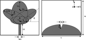
The proposed planar monopole antenna fed by a microstrip line is shown in Fig. 1, which is printed on an FR4 substrate with thickness of 1.6 mm, permittivity of 4.3 and loss tangent 0.025. The basic clover monopole antenna structure consists of a clover geometry (fusion of four elliptical geometries), a microstrip feed line and a semi elliptical ground plane. The prototype is connected to a 50 Ω SubMiniature version-A (SMA) connector. The antenna input impedance characteristics should be flat over the operating frequency band [Reference Deng, Xie and Li3], which is satisfied for the proposed antenna. The partial ground plane is chosen of the semi-ellipse shape in order to obtain linear phase characteristics of the reflection co-efficient [Reference Kimouche, Abed, Atrouz and Aksas18]. The size of the ground plane is crucial in achieving the ultra wide bandwidth [Reference Ershadh, Krishna, Bhayaveni and Subramanian19].
The clover shaped antenna front and rear view with dimensions.

Figure 1 shows the antenna schematic and the antenna structure is based on a monopole design. The width of the microstrip feed W1 is fixed at 3 mm and the length of the microstrip feed L1 is fixed at 15 mm, to match 50 Ω impedance and to achieve an optimum bandwidth, respectively. The semi minor axis length Y and semi major axis length X of the primary ellipse are 6 mm and 12 mm, respectively. The pair of secondary ellipses with semi minor axis length B = Y = 6 mm and semi major axis length A = 1.5X = 18 mm, are rotated 45° on either planes with respect to the horizontal axis and a vertical tertiary ellipse of semi minor axis length XA = 10 mm and semi major axis length YA = 15 mm is created and all are fused to form the clover structure. The ground plane is provided below the feed in the rear plane and the optimum V cut (triangular shape with dimensions a = 5.2 mm and b = 3 mm) is etched out of the semi ellipse ground plane with center as the midpoint of the bottom edge of the antenna and semi minor axis length 14.5 mm and semi major axis length 25 mm. The overall dimension L × W of the antenna is 50 × 45 mm2.
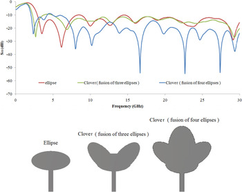
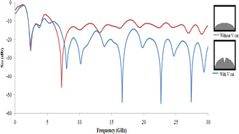
In Fig. 2, the evolution of the clover antenna has been shown with respect to the performance of the reflection coefficient characteristics. Initially an ellipse was formed and the |S 11| was observed to be greater than or equal to 10 dB at frequencies greater than 2.7 GHz and the values of |S 11| is less at higher frequencies. After ellipse, a small clover fusion of primary ellipse and secondary ellipses (rotated theta degrees) gives a good S 11 characteristics at a much lower frequency 2.2 GHz. Still the values of |S 11| is less at higher frequencies. Another ellipse fused vertically on the small clover, results in a good S 11 characteristics at 1.9 GHz and a very high value of |S 11| is achieved at higher frequencies, resulting in a SWB from 1.9 GHz to over 30 GHz. Figure 3 illustrates the importance of the V cut at the semi-circular ground plane. It is noted that with V cut, the |S 11| is greater and improved over a wideband of frequencies. To achieve impedance matching that results in bandwidth enhancement, the technique of loading a triangular notch at the feeding position in the ground plane is introduced [Reference Huang and Hsia8, Reference Kim and Park9, Reference Chen, Sim and Row13].
Formation of the clover geometry with respect to reflection coefficient characteristics.

The reflection coefficient characteristics with variations in the ground plane distances (without v cut and with v cut).

III. PARAMETRIC STUDY
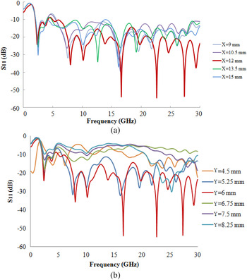
In this section, the parameters of this proposed antenna are studied by changing one parameter at a time and keeping the other parameters unchanged. As the length L1 and width W1 of the microstrip feed has been fixed for impedance matching, the optimal parameters taken for the study are the length of semi major axis X of the primary ellipse (in mm keeping semi minor axis of the primary ellipse constant) in the antenna structure and the various theta values of the rotated secondary ellipses. In Fig. 4(a), it is observed that when X is varied from 9 to 15 mm, the lower band edge frequency remains constant and at X = 12 mm an optimum wide bandwidth with good S 11 characteristics, from 1.9 GHz to frequency over 30 GHz has been obtained. In Fig. 4(b), it is observed that when Y is decreased from 8.25 to 4.5 mm, the bandwidth increases with good values of |S 11| and slight frequency shift occurs at the lower band edge. It can also be noted that at Y = 6 mm, the lower cut off frequency is 1.9 GHz which is comparatively less than the other Y values and the other Y values has lower |S 11| compared with Y = 6 mm. Therefore at Y = 6 mm an optimum wide bandwidth with good S 11 characteristics, from 1.9 GHz to frequency over 30 GHz has been obtained.
(a) The reflection coefficient characteristics of various semi major axis length X of the ellipse in the clover geometry (in mm). (b) The reflection coefficient characteristics of various semi minor axis length Y of the ellipse in the clover geometry (in mm).

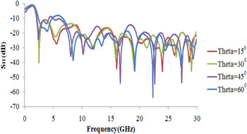
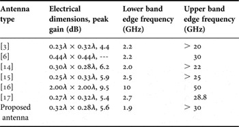
In Fig. 5, the theta values of the rotated secondary ellipses is varied and is increased from 15° to 60° (keeping X as a constant of 12 mm and Y as a constant 6 mm), a slight frequency shift occurs. When the theta values is varied from 15° to 45°, the lower band edge frequency reduces to 1.9 GHz and when the theta value was increased from 45° to 60°, the lower band edge frequency increases from 1.9 GHz to frequency greater than 1.9 GHz. Therefore at a theta of 45°, a wide bandwidth from 1.9 GHz to frequency over 30 GHz is obtained. Thus semi major axis length X of 12 mm, semi minor axis length Y of 6 mm and theta of 45° was inferred as the optimum semi major axis, semi minor axis length, and theta angle of rotation, respectively. Table 1 lists the comparison parameters of various prototypes. As seen in Table 1, the proposed antenna is one of the compact antenna in comparison with other prototypes in the literature.
The reflection coefficient characteristics of various theta values (in degrees) of the two petals (ellipses) of the clover geometry.

Dimension and frequency comparison.

IV. MEASURED RESULTS AND DISCUSSIONS
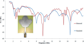
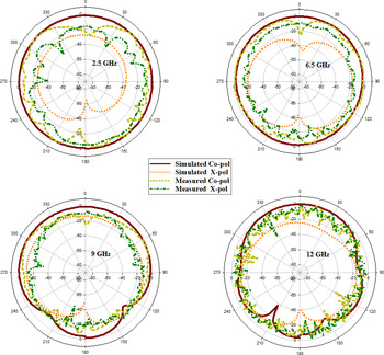
Figure 6 shows the simulated and measured reflection coefficient (|S 11|) characteristics. It is clearly seen that the clover antenna has a wide impedance bandwidth (at −10 dB of |S 11|) from 1.9 to 20 GHz in simulated and in measured the bandwidth (at −10 dB of |S 11|) from 2 to 20 GHz was obtained. From the simulated and measured reflection coefficient results shown in Fig. 6, the lower band edge frequency is at 1.9 GHz and 2 GHz, respectively. Measured reflection coefficient (|S 11|) of the designed antenna match reasonably with the simulation results. In the measured results there exists some undulations which may be due to the limitations of the SMA port used and the measured reflection coefficient antenna has been reduced due to minute errors in the fabrication process (cutting off edges at the clover geometry). The proposed antenna has a measured 14 dB bandwidth from 5.9 to 13.1 GHz. Figure 7 depicts the simulated and measured radiation pattern of the aforementioned antenna in the xz-plane for 2.5, 6.5, 9, and 12 GHz. Figure 8 illustrates the simulated peak gain variations for various frequencies and cross symbol indicates the measured gain values for 2.5, 6.5, 9, and 12 GHz. It is noted that, in the operating band from 1.9 to 12 GHz, gain varies from minimum value of 0.7 dB (at 4.5 GHz) to a maximum value of 5.6 dB (at 12 GHz) and from 12 to 20 GHz peak gain drops to 2.9 dB, due to dielectric losses at higher frequencies.
Simulated and measured reflection coefficient characteristics of the clover antenna.

Simulated and measured radiation pattern (xz-plane) at 2.5, 6.5, 9, and 12 GHz.

Simulated gain (dB) versus frequency (GHz). Cross symbol indicates the measured gain values for 2.5, 6.5, 9, and 12 GHz.

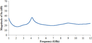
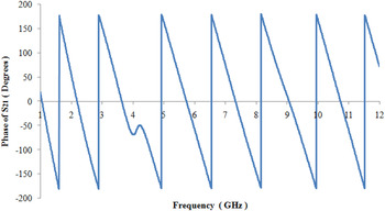
In order to validate the SWB clover structured antenna for UWB applications, time domain analysis was also carried out. Reference [Reference Ershadh, Krishna, Bhayaveni and Subramanian19–Reference Yoon, Yoon, Kim and Lee26], deals with time domain analysis. UWB systems use narrow pulses of very short duration for transmitting signals. By considering the antenna system as a two-port network, the transmission scattering parameter S 21 of the antenna is plotted in simulation [Reference Ershadh, Krishna, Bhayaveni and Subramanian19, Reference Gao, Hu and Zhang20]. Two antennas (transmitter and receiver) are placed with a separation distance of 100 mm [Reference Ershadh, Krishna, Bhayaveni and Subramanian19, Reference Mao, Yeh and Chen24, Reference Yoon, Yoon, Kim and Lee26] in side–side orientation for measuring the transmission characteristics and the pulse handling capability of the proposed antenna. Transmitter antenna functions as Port 1 and Receiver antenna functions as Port 2. The transmission characteristics between them is recorded and plotted. The simulated magnitude and phase of the transmission scattering parameter which indicates the antenna system transfer function are shown in Figs 9 and 10. The magnitude of the antenna system transfer function should be frequency flat over the operation band. The magnitude plot of system transfer function of the proposed antenna shows that it is nearly flat over the UWB operating band. Similarly, the phase of antenna system transfer function ∠S 21 should vary linearly over the operation band [Reference Ershadh, Krishna, Bhayaveni and Subramanian19, Reference Yoon, Yoon, Kim and Lee26]. Antenna system transfer function phase ∠S 21 of the proposed antenna is almost linear over the entire band. From the magnitude and phase plots of the transfer function, the proposed antenna is suitable for UWB pulse communications. Antenna system transfer function phase ∠S 21 is almost linear over the entire band and there exists some nonlinearity around 4 GHz, which is due to the low gain value [Reference Quintero, Zurcher and Skrivervik22] and lower value of |S 11| and |S 21| at 4 GHz.
Magnitude of antenna system transfer function (S 21). (Plotted when two identical clover shaped antennas (transmitter and receiver) are placed with a separation distance of 100 mm).

Phase of antenna system transfer function (∠S 21). (Plotted when two identical clover shaped antennas (transmitter and receiver) are placed with a separation distance of 100 mm).

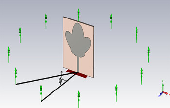
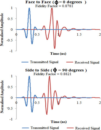
Furthermore, to measure the pulse handling capability of the proposed clover structured antenna, time-domain analysis was carried out with fidelity factor calculation using (1) and by using virtual probes as receivers. The fidelity factor, as defined in [Reference Kwon21], quantifies the degree to which the radiated E-field waveform of a transmitting antenna resembles the driving voltage. This is calculated with the cross-correlation of the radiated E-field and the input signal, as stated in [Reference Quintero, Zurcher and Skrivervik22]. In order to obtain the radiated E-field, probe is used as receiver. Figure 11 illustrates the time domain setup, for calculating the fidelity factor where the transmitter antenna (clover structured antenna) and receiver (virtual far-field E-field probes) are placed with a separation distance of 100 mm and “φ” is the angle of placement (in degrees) of the receiver probes with respect to the transmitter antenna. The transmitter is excited by a Gaussian signal (3.1–10.6 GHz) and the received signal is obtained. Transmitted and received signals are shown in Fig. 12. The fidelity factors in the case of face–face (φ = 0°) and side–side (φ = 90°) are obtained as 0.8781 and 0.8821, respectively. The input pulse and the received pulse are shown in the same graph so as to compare the input and received pulse shapes. From Fig. 12, it can be seen that the received pulse almost preserves the pulse shape of the excited input pulse. The normalization is done in order to compare only the shape of the pulses, and not their magnitude, as the received signal R s is expected to be much lower than the transmitted pulse T s . The cross-correlation between both signals is done at every point in time and the maximum value is obtained as fidelity factor when both pulses overlap [Reference Quintero, Zurcher and Skrivervik22] and is given by equation (1).
 $$\hbox{Fidelity Factor} = \max \int_{ - \infty} ^{ + \infty} {\widehat{T}_s (t)\widehat{{R_s}} (t + \tau )}.$$
Transmitter antenna and receiver probes arrangement. (“φ” is the angle of placement of the receiver probes with respect to the transmitter antenna).

Transmitted signal by clover shaped antenna and received signal by using virtual probes (face–face and side–side orientations with fidelity factor of the proposed antenna).

For various angles of probe placement, the fidelity factor was obtained and is tabulated in Table 2. From Table 2, the average fidelity of 0.8861 is obtained, which is much higher than the commonly accepted minimum value of 0.5 [Reference Quintero, Zurcher and Skrivervik22].
Fidelity factor.

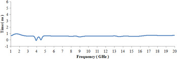
Group delay is another important parameter to characterize the UWB antenna behavior, which measures the degree of distortion of signal waveforms. Group delay is defined as the derivative of the phase response versus frequency [Reference Quintero, Zurcher and Skrivervik22]. In Fig. 13 there exists some dips at 4 and 4.5 GHz, which is due to dependence of the group delay with the nonlinearity of ∠S 21 [Reference Quintero, Zurcher and Skrivervik22], low gain value, low |S 11| and |S 21| at those frequencies. The group delay graph of the proposed antenna is illustrated in Fig. 13. It is noted that the group delay of the antenna is almost flat over the entire operating band. The variation in time or delay of the frequency components of the signal is less for the entire operating band. It is almost constant for all frequencies which shows that all frequency components of the transmitted pulse remain intact, shows the better performance of the proposed antenna in terms of UWB, and SWB characteristics.
Group delay of the clover structured antenna.

V. CONCLUSION
A clover shaped SWB planar printed monopole antenna has been presented. From the results it is evident that the clover structured antenna has a super wide impedance bandwidth (at -10 dB of |S 11|) from 1.9 GHz to frequency over 30 GHz. The designed antenna has a low profile, simple configuration, and is of low cost. Measured reflection coefficient (|S 11|) and radiation pattern of the designed antenna agree reasonably well with the simulation results. The design exhibits nearly constant group delay, almost flat transfer functions, and phase linearity. The time domain analysis shows that the proposed antenna can be a potential candidate for UWB pulse communications. The average fidelity factor of the proposed antenna is also much higher than the acceptable value. This antenna can support many wireless services and hence is attractive for UWB and multi-band wireless devices.
ACKNOWLEDGEMENT
This work was supported by the Anna Centenary Research Fellowship, College of Engineering Guindy, Anna university, Chennai 600025, India. The authors acknowledge Thiagarajar College of Engineering, Madurai, India for their kind help in the measurements.
 Sandeep Kumar Palaniswamy is currently working towards the Ph.D. degree at College of Engineering Guindy, Anna University, Chennai, India. His research interests include wideband antennas and UWB antennas.
 Malathi Kanagasabai was born in India. She completed her Ph.D. degree in Microwave Engineering from the Department of Electronics and Communication Engineering, College of Engineering Guindy, Anna University, Chennai. She is currently Associate Professor in the Department of Electronics and Communication Engineering, Anna University, Chennai. Her research interests include microwaves, transmission lines, antenna structures, and high speed systems.
 Arun Kumar Shrivastav was born in India. He completed his Ph.D. degree from the Department of Electronics and Communication Engineering, Anna University, Chennai. He is currently working as Scientist Fat Center for Electro Magnetics, Society for Applied Microwave Electronics Engineering and Research (SAMEER), Chennai, India. His research interests include microwaves, transmission lines, antenna structures, and high speed systems.
 Gulam Nabi Alsath is working as an Assistant Professor in the Department of ECE, SSN College of Engineering, Chennai. He is currently pursuing his Doctorate degree at Anna University. His research interests include design of reflector antennas, planar antennas, multiband antenna structures, and antennas for vehicular applications.
 Sangeetha Velan is currently working towards the Ph.D. degree at College of Engineering Guindy, Anna University, Chennai, India. Her research interests include microwave couplers and antenna design.
 Jayaram Kizhekke Pakkathillam is currently working towards the Ph.D. degree at College of Engineering Guindy, Anna University, Chennai, India. His research interests include circularly polarized antennas and RFIDs.