1. Introduction
With diverse areas of application, wearable robotic devices gained attention in the past decade. These devices, collectively known as exoskeletons, are studied for human strength augmentation as well as for rehabilitation. Following this lead, various application specific devices including some patented ones have been proposed in literature [Reference Tung, Pillai and Kazerooni1–Reference Deshpande and Agarwal6]. The application areas vary diversely from medical, military to gaming industries [Reference Zheng, Shi and Yu7–Reference Park, Jo, Lee and Bae9]. In the medical industry, exo-skeletons can be used as rehabilitation assistance devices for recovery of patients suffering from temporary muscular malfunction (neurological disorders). The rehabilitation process of a patient suffering from neurological disorders requires repetitive and intense therapeutic sessions. There is evidence that wearable robotic systems are a viable option to accurately perform such therapeutic sessions with minimal human intervention [Reference Hwang, Seong and Son10], thus reducing the treatment expenses and enhancing effectiveness. These devices can be customized for limb or joint specific physio therapy sessions. Such sessions are more uniform as compared to, when conducted by different therapists, and at the same time performance of the patient can be recorded to be analyzed later by concerned specialists.
Amongst the limbs/joints that may require rehabilitation, the index finger is one of the most important due to its mobility and independent muscle attachments. It not only helps in giving a powerful grip but also allows manipulation of small objects with great precision for common daily tasks. There are three joints (MCP (metacarpophalangeal), PIP (proximal interphalangeal), DIP (distal interphalangeal) joints) and three phalanges (proximal, middle, and distal) in a human index finger. The basic representation of these is shown in Fig. 1. Thus an index finger exoskeleton should be compatible with these joints and phalanges. Furthermore, the exoskeleton should be capable of accurately and safely guiding the finger towards correct rehabilitation trajectories. For this purpose force control strategies (stiffness control, admittance control, impedance control [Reference Zeng and Hemami11], and assist-as-needed [Reference Cai, Fong, Otoshi, Liang, Burdick, Roy and Edgerton12]) are shown to be more productive than position control based approaches as the former require active efforts to be put in by the patient rather than just following a predefined trajectory in the later approach. Various force control based exercise profiles can be created to provide the patient with physiotherapy exercises resulting in better recovery results [Reference Takahashi, Der-Yeghiaian, Le, Motiwala and Cramer13]. Due to its importance in daily life a force controlled index finger exoskeleton rehabilitation device has been proposed in this paper.
Joint representation of human hand.

In physical human machine interaction, safety is of paramount importance. It has been observed that a comfortable interaction and human safety can be implemented through use of series elastic actuators (SEA). Passivity of a SEA can be controlled by use of appropriate compliant element and controller gains. SEAs can provide decoupling of actuator inertia, back-driveability, better shock tolerance, and high controller gains however their use also reduces the system bandwidth [Reference Yu, Huang, Chen, Pan and Guo14]. Rehabilitation devices are required to operate at lower response speeds therefore, for rehabilitation devices a lower system bandwidth may not hamper system efficiency [Reference Agarwal, Fox, Yun, O’Malley and Deshpande15]. Some of the proposed SEA based exoskeletons for various parts of the human body like lower extremity [Reference Wang, Chen, Li, Dong, Du, Shen and Zhao16], upper limb [Reference Gopura, Bandara, Kiguchi and Mann17], wrists [Reference Su, Yu, Lin and Lan18], fingers [Reference Agarwal, Fox, Yun, O’Malley and Deshpande15], and others have shown good results towards achieving a safe compliant interaction and force control accuracy.
We set our goal to design a robotic exoskeleton capable of facilitating rehabilitation of the index finger. In order to satisfy rehabilitation needs, it must comply to the following design constraints
• should be biologically compatible with the finger movements and should not hamper the normal finger range of motion
• should have a comfortable interaction avoiding joint misalignment
• should have low reflected inertia and high back-drivability
• should be low-cost and affordable
• should be adjustable to various finger sizes varying from individual to individual
• should be force controlled and able to generate virtual fixtures/tunnels in order to gently guide the finger towards the required rehabilitation protocol
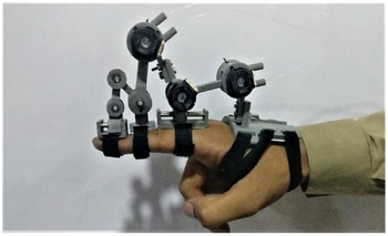
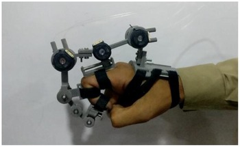
Two notable SEA based finger exoskeletons have been proposed in literature. Agarwal et al. [Reference Deshpande and Agarwal6, Reference Agarwal, Fox, Yun, O’Malley and Deshpande15] presented the first SEA based finger exoskeleton incorporating a cable drive design and linear springs. Furthermore Marconi et al. [Reference Marconi, Baldoni, McKinney, Cempini, Crea and Vitiello19] presented an exoskeleton for finger and thumb incorporating torsional spring based SEAs. In continuation of the research, we present a torsional spring based finger exoskeleton (named as F-Exo) to be used for rehabilitation of temporary post-stroke finger disabilities (Figs. 2, 3 and 19). We have taken the research forward by proposing force controlled trajectories for the finger exoskeleton. Such trajectories serve to gently guide the finger towards the correct rehabilitation protocol, thus acting as an effective replacement of intervention by a human therapist. We present an overview and limitations of previously developed hand/finger exoskeletons in Section 2. Design requirements/constraints are discussed in Section 3. Subsequently mechanical design and kinematics, controller design, testing, and results are presented in Section 4.
2. Related Work and Research Gaps
A number of different hand exoskeletons have been presented till date. These exoskeletons can be broadly categorized into active and passive, which are covered in the subsequent sub sections. Being relevant to the current research, only electrically actuated exoskeletons are reviewed. Pneumatically actuated exoskeletons [Reference Takahashi, Der-Yeghiaian, Le and Cramer20, Reference Wu, Huang, Wang and Xing21] have also been presented to control finger movements through use of actuators. Actuation has also been implemented by filling of pressurized air in specially designed gloves [Reference Stilli, Cremoni, Bianchi, Ridolfi, Gerii, Vannetti, Wurdemann, Allotta and Althoefer22–Reference Chu and Patterson24]. However these type of actuation schemes either lack individual joint control over complete finger or are less accurate to achieve desired positions. Therefore, they have not been made part of the review. Exoskeletons have been presented with soft robotics material however such devices have positional accuracy limitations [Reference Haghshenas-Jaryani, Patterson, Bugnariu and Wijesundara25].
2.1. Passive actuation based exoskeletons
A 4-bar linkage mechanism designed to carry out a coordinated movement for fingers and thumb has been presented by Brokaw et al. [Reference Brokaw, Black, Holley and Lum26]. This rehabilitation device named as HandSOME (Hand Spring Operated Movement Enhancer) is a one DOF device having passive actuation mechanism. The portable light weight device (128 g) is suited for flexor hypertonia. However, a passive device is not suitable for accurate force control and implementation of force controlled trajectories.
2.2. Active electrically driven exoskeletons
In this section exoskeleton devices presented in literature are compared over different parameters with their advantages and disadvantages:
2.2.1. Force transmission mechanism
Force transmission mechanism can be categorized in the following categories:
• Direct linkages. Different force transmission mechanism have been proposed which in turn have their own inherent advantages and disadvantages. The application of force through use of direct linkages [Reference Fontana, Dettori, Salsedo and Bergamasco27, Reference Ertas, Hocaoglu and Patoglu28] increases the system bandwidth, however, have low kinematic transparency and poor motor inertia decoupling. Using direct linkages also has the added disadvantage of the restriction to mount actuators on the hand/arm which is inconvenient due to weight (as actuators are typically heavy) [Reference Taheri, Rowe, Gardner, Chan, Gray, Bower, Reinkensmeyer and Wolbrecht29–Reference Sarakoglou, Brygo, Mazzanti, Hernandez, Caldwell and Tsagarakis31]. Also usage of gears in the force transmission link eliminates back-drivability [Reference Jones, Wang, Morrison, Sarkar and Kamper32–Reference Li, Yan and Ren34].
• Bowden cable mechanism. In order to reduce weight on the hand of the wearer, actuators are needed to be placed remotely while the force applied by the actuators can be transmitted on the joints by the use of bowden-cable transmission mechanism [Reference Agarwal, Fox, Yun, O’Malley and Deshpande15, Reference Li, Zheng, Zhang and Yao35]. This also allows the wearer to move his/her hand as per convenience and increases the workable area [Reference Ferguson, Dimapasoc, Shen and Rosen36]. However, this approach is also coupled with nonlinear force transmission due to frictional effects between cable and sheath. These nonlinear frictional effects can be accounted-for in the control algorithm which turns out to be relatively challenging due to multiple factors (length,time-varying bending angles in cable transmission mechanism, nonlinear friction between cable and sheath) affecting the friction.
2.2.2. Force sensing techniques
Force sensing technique becomes important when targeting a low-cost force controlled device instead of position controlled device [Reference Li, Yan and Ren34]. Designs incorporating dedicated force sensors can become costly [Reference Sarakoglou, Brygo, Mazzanti, Hernandez, Caldwell and Tsagarakis31]. Use of force sensors also induces undesired noise [Reference Jones, Wang, Morrison, Sarkar and Kamper32] and in some cases it becomes difficult to achieve perpendicular force on the sensor which gives inaccurate force sensing. Using SEA has been identified as a low cost force sensing technique through use of elastic elements in series with actuator and end effector. Torque can be directly measured at a certain joint using known stiffness compliant element and positional encoder using the Eq. (1).
 \begin{equation} \tau =K\theta \end{equation}
Where K is the known spring constant and
 $\theta$
is the deflection measured by position encoder.
2.2.3. Controlled degree of freedom
Under-actuated devices, having single interaction point with finger at distal phalange are shown to be a viable option for interaction with virtual reality [Reference Sarakoglou, Brygo, Mazzanti, Hernandez, Caldwell and Tsagarakis31, Reference Ferguson, Dimapasoc, Shen and Rosen36, Reference Bianchi37] however, a rehabilitation device is required to have more control over the finger so that all of its movement can be controlled.
2.2.4. Weight
Weight is another important parameter of exoskeletons dictating the wearability and comfort of user. Various light weight exoskeletons have been proposed. Agarwal et al. [Reference Agarwal, Fox, Yun, O’Malley and Deshpande15] proposed an SEA based exoskeleton weighing approx 80 g and Marconi et al. [Reference Marconi, Baldoni, McKinney, Cempini, Crea and Vitiello19] proposed an exoskeleton for index finger and thumb with approx 420 g of weight. Some other exoskeletons weighing 140 g for CAFE [Reference Jones, Wang, Morrison, Sarkar and Kamper38], 185 g for Ertas et al. [Reference Ertas, Hocaoglu and Patoglu28], 270 g for Aragón et al. [Reference Aragón-Martínez, Arias-Montiel, Lugo-González and Tapia-Herrera39], and 250 g for iHandRehab [Reference Li, Zheng, Zhang and Yao35] have been proposed. The weight of exoskeleton presented in this paper is approx 240 g comparable to previously proposed SEA based exoskeletons.
2.2.5. Uni-directional versus bi-directional force control
Hand exoskeletons for interaction with virtual reality have been developed (such as the commercially available CyberGrasp), however these devices are capable of exerting uni-directional forces. Also, this unidirectional force for each finger (limiting flexion motion only) is limited to a single DOF and lacking individual joint control. Unidirectional control of joints for rehabilitation covers half of the aim of rehabilitation, as either control over flexion or extension will not be possible [Reference Lemerle, Nozaki and Ohnishi40].
2.2.6. Self-alignment
Alignment of exoskeleton and minimizing the effect on natural motion is of primary concern. An exoskeleton which specifically focuses on self alignment (including the MCP joint) has been presented [Reference Sun, Li and Cheng41] in literature. It uses a custom kinematic mechanism including a sliding joint to reduce reaction forces significantly while minimizing restriction to natural finger movements. The work has been taken forward and optimal measures for manipulability have been proposed [Reference Li, Cheng and Sun42]. Another 2-DoF design that adapts to different finger sizes has been presented [Reference Carbone, Gerding, Corves, Cafolla, Russo and Ceccarelli43]. The exoskeleton also ensures comfort by eliminating shear force along the finger. These devices address a very important issue in exoskeletons (self alignment), however, do not feature SEA for compliant and accurate torque control. SEA is considered important for exoskeletons as they are directly in contact with human limbs.
2.3. Research gaps
Upon reviewing the design and performance of exoskeleton devices it becomes clear that there are various challenges to be overcome [Reference Li, Yan and Ren34]. These can mainly be categorized as compatibility/alignment with human joints and accurate force control. The proposed design aims to overcome these challenges by using a suitable design and force control through the use of SEAs [Reference Aragón-Martínez, Arias-Montiel, Lugo-González and Tapia-Herrera39, Reference Li, Yan and Ren34]. Furthermore, it adds value to the research by presenting force controlled trajectories and rendering of virtual objects. In literature, such trajectories have been presented for upper extremity rehabilitation devices [Reference Sarac, Ergin, Erdogan and Patoglu44], however, they have not been presented for finger exoskeletons.
Extended position of the proposed exoskeleton.

Flexed position of the proposed exoskeleton.

The kinematics of the proposed exoskeleton comprises of three coupled closed chains similar to the exoskeleton presented by Agarwal et al. [Reference Deshpande and Agarwal6, Reference Agarwal, Fox, Yun, O’Malley and Deshpande15] (used for research purposes only), however our designed exoskeleton is physically more robust as it houses torsional elastic element inside SEA shell (see Fig. 4). Furthermore, we have also reduced the number of position sensors (3 sensors used against 5) on the device which would help in reducing the fabrication cost of exoskeleton and enhance its reliability.
3. Design Considerations and Decisions
The index finger has two types of movements that can be modeled for the device namely flexion-extension and abduction−adduction movements. It has been suggested that the abduction−adduction movements do not play a significant role in normal hand rehabilitation exercises like briefcase grip, grasping, pinching, and so forth [Reference Lee and Jung45]. Also, the integration of abduction−adduction motion may result into significant design challenges, therefore, we have restricted ourselves to the provisioning of active actuation for flexion-extension motion only. The rotation of DIP joint is anatomically coupled with the rotation of PIP joint therefore we do not provide active control over DIP joint [Reference Levangie and Norkin46].
CAD model of the proposed finger exoskeleton. Six revolute joints are marked from R1 to R6. Two passive prismatic joints are shown. Two series elastic actuators are installed at positions marked with elastic element housing. Three optical encoders are mounted at R1, R2, and R3. Lengths of links between R1 and hand base (not shown) and R2 and R3 can be adjusted.

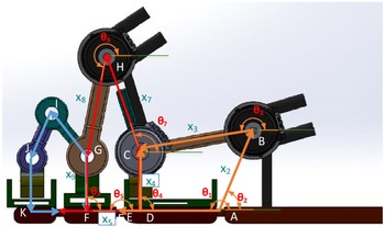
Three coupled closed chains marked with orange red and blue colors for Loop-1, 2, and 3, respectively. Link lengths are represented from
 $x_1$
to
 $x_9$
. Link angles marked from
 $\theta _1$
to
 $\theta _9$
. Angles
 $\theta _3$
,
 $\theta _7$
and
 $\theta _8$
are measured through three rotary optical encoders. Whereas
 $\theta _1$
and
 $\theta _5$
are the required MCP and PIP angles to be controlled through
 $\theta _3$
and
 $\theta _8$
.

3.1. Ranges of motion
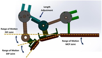
The mean and standard deviation of range of motion (ROM) for MCP, PIP, and DIP joints [Reference Ertas, Hocaoglu and Patoglu28, Reference Becker and Thakor47], bi-directional peak torque applied during rehabilitation exercises by experienced therapists [Reference Ueki, Kawasaki, Ito, Nishimoto, Abe, Aoki, Ishigure, Ojika and Mouri48], torque bandwidth of human force control loop [Reference Chan and Childress51] and angular velocity [Reference Kawasaki, Kimura, Ito, Nishimoto and Hayashi50] of index finger are presented in Table I. ROM values have been taken from research conducted by Becker et al. [Reference Becker and Thakor47] which presents an extensive experimental study on Range of Motion of Human Fingers on human subjects. Fingers and joints were marked with a high contrast paint and camera images were analyzed to find ranges of motion. Subjects were asked to execute maximum flexion/extension of fingers, and the angles traversed by each joint were measured. The proposed design is targeted for mean ROM of all joints, with reference shown in Fig. 6.
Targeted range parameters for index finger exoskeleton.

Reference for range of motion (ROM) calculations and length adjustment for varying finger lengths.

3.2. Strategy to avoid joint misalignment
From the comparison of existing exoskeletons we observed that significant parasitic forces were generated on the human finger along the lateral axis of phalanges which can be detrimental for rehabilitation of patients. Therefore, there was a need to keep these forces minimal. All the forces applied through actuators must be restricted such that it can only rotate the finger across its natural rotation axes. Passive joints have been incorporated in the exoskeleton, where active joint alignment is over looked, so that the axis of rotations of exoskeleton and human finger are automatically aligned and no lateral force is exerted on the finger. Subsequently, moments generated on the phalanges through motors can only generate torques across the axis of finger joint.
3.3. Compliant interaction through use of SEAs
SEAs provide many benefits in force control of robots in unconstrained environments. These benefits include inherent shock tolerance, high force fidelity, low impedance, low friction, and good force control bandwidth [Reference Pratt, Krupp and Morse52]. SEAs tend to have more stable force control because the force control problem is converted to a position control problem, higher gains are possible and the spring filters out the high-frequency disturbances of the mechanism. SEAs also offer a cost effective solution to torque measurements while ensuring a margin for human safety and interaction compliance. Use of SEAs decouples motor inertia from the end-effector and introduces back-driveability in the system. Bandwidth of the overall system is reduced (depending on the spring stiffness [Reference Eppinger and Seering53]). Increase in bandwidth requires increasing spring stiffness or using special control schemes [Reference Lee, Kim, Singh and Ryu54]. However, exoskeletons that are used for rehabilitation of patients do not require a high bandwidth (1.5 Hz is considered sufficient for activities of daily living [Reference Gasser and Goldfarb49]), therefore, use of SEAs with low stiffness spring is a viable option.
3.4. Size adjustment to match variable finger sizes
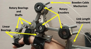
The wearer of exoskeleton can have different phalange lengths and ROM of fingers. Therefore adaptability to various finger sizes is to be considered as an intrinsic feature in the design phase of exoskeleton. The design includes a Length Adjustment feature, in which the links between R1-base and R3-R2 are designed in two parts that have slots built into them. The two parts are connected to each other by a screw and nut. Thus, the length of links can be adjusted (see Fig. 4). In this design, the length adjustment feature has been used to ensure that the exoskeleton properly fits the wearer. A proper characterization for multiple finger sizes (according to NASA Anthropometery Data [55]) is planned during future work. Furthermore, physical limits other than software defined safeties are incorporated in the design to restrict motion in a controlled paradigm (See Fig. 7). The lengths of prismatic joints are planned such that they will restrict extension movement beyond natural limits.
Motion limiters implemented in design.

3.5. Software and mechanical safety
Whenever robots come in interaction with humans, human safety is of paramount importance. We have developed the mechanism such that it is not able to rotate in the forbidden workspace regions where it can cause harm to human finger (see Fig. 7). Any motion out of ranges mentioned in Table I is mechanically limited. Furthermore, in addition to mechanical motion limiters, the controller algorithm saturates outputs in those regions and does not generate any such command that tries to twist the finger out of the desired range.
3.6. Remote/local actuation and force transmission mechanism
Actuators can be the heaviest component in the robotic exoskeletons. In order to keep the weight of wearable device low, we have provide remote actuation to the exoskeleton using bowden cable mechanism instead of rigid links as a means of transfering applied force. The nonlinear frictional forces created in the transmission due to the bowden cable mechanism have been compensated in the control loop (very fast inner position control). Weight of the transmission has been kept low by using fishing wire as cables and surgical incision tubes as the outer sheath.
4. Mechanical Design and Modeling
Mechanical design has been modeled in SolidWorks
 $^{\circledR }$
with lengths of links set to cover ROM as tabulated in Table I. The index finger exoskeleton design presented in this paper has three DOFs. It has active actuation in two DOFs in MCP and PIP joints while having passive DOF in the DIP joint. Linear bearings (implementing passive prismatic joints) in two joints of the exoskeleton (at point D and K (see Fig. 4)) are incorporated in the design at two interaction points. The third interaction point, that is, middle phalange is rigidly latched with the exoskeleton. Any translational force generated in the finger that may cause deviation in the natural rotation axis of finger joints (or have an adverse affect on the subject under rehabilitation) is compensated by these sliders in form of lateral movement. Thus, only the normal component of force is allowed to effectively rotate the human finger. Mean Lengths of the index finger used in the model are 39.78 mm for proximal phalange (standard deviation of
 $\pm$
4.94 mm), 22.38 mm for middle (standard deviation of
 $\pm$
2.51 mm) and 15.82 mm for distal phalange (standard deviation of
 $\pm$
2.26 mm) [Reference Alexander and Viktor56].
4.1. CAD model
We have kept six revolute joints in the model (marked with R1 trough R6 in Fig. 4) and two prismatic joints over proximal and distal phalanges each. The device can be strapped on the hand with the help of velcro straps at four points (hand base, proximal phalange, middle phalange, and distal phalange). The model incorporates two SEAs placed at joints R1 and R3 for measurement of joint torques and keeping the interaction compliant. We kept the material properties of PLA material which was later used for fabrication of exoskeleton. We also kept provisioning for length adjustment of exoskeleton to match finger lengths of different persons in two parts as mentioned in Fig. 4. A total of 17 parts were created in the model to complete the actuation chain. In this proposed design we have designed SEA shell in a way that the elastic element can be replaced without dis-assembling complete SEA. This can be done by unscrewing the side of SEA and springs can be replaced to increase or decrease the effective applied torque by SEA. This adjustment has been planned to enhance the application of force by using a stiffer spring for virtual reality interaction based applications.
4.2. Simscape model
The Solidworks model was then imported to Simulink using Simscape Multibody Plugin to implement the controller and run simulations prior to 3D printing of model. This enabled us to reduce hardware design iterations. Simscape model provided us an accurate reference of exoskeleton conserving link inertias, joint properties, and other physical attributes of exoskeleton. This model also provided us the option of offline robot programing and development of control algorithm prior to physical manufacturing and then controlling the exoskeleton.
4.3. Kinematics
We solved forward and inverse kinematics of the device by expressing two closed loop equations each for Loop-1 and Loop-2. Results are compared with the Simscape model and root mean square errors are reported against each.
4.3.1. Loop-1 kinematics
Loop closure equation for Loop-1 (see Fig. 5 orange color) comprising of vectors AB, BC, DC, and AE is as under:
 \begin{align} \textrm{AB}+ \textrm{BC} &= \textrm{AD} + \textrm{DC} \nonumber \\[3pt] x_2 e^{i\theta _2} + x_3 e^{i\theta _3} &= x_{un} e^{i\theta _1} + x_4 e^{i\theta _4} \end{align}
Here
 $\theta _4=\theta _1-\pi/2$
. The loop closure equation was used to derive forward and inverse kinematic relations for position and velocity. The relations are attached as Appendix to this paper.
4.3.2. Loop-2 kinematics
The movement of Loop-2 (see Fig. 5 red) was found to be coupled with loop-1. Due to coupling between both loops the derivation of loop closure equation for Loop-2 introduced significant challenge. Loop-2 comprised of the following vector and loop closure equation:
 \begin{align} \textrm{FE} + \textrm{ED} + \textrm{DC} + \textrm{CH} + \textrm{HG} + \textrm{GF} &= 0 \nonumber \\[3pt] x_5e^{i\theta _5}+x_{un}e^{i\theta _1}+x_4e^{i\theta _4}+x_7e^{i\theta _7}\qquad\qquad &\nonumber \\[3pt] +x_8e^{i\theta _8}+x_9e^{i\theta _9}&=0 \end{align}
Here
 $\theta _4=\theta _1+\pi/2$
and
 $\theta _9=\theta _5+3\pi/2$
. Forward and inverse kinematic relations for position and velocity for Loop-2 were calculated using loop closure Eq. (3). The relations are attached as Appendix to this paper.
Kinematic equations for Loop-3 were not expressed because distal phalange was not actively controlled. As the PIP and DIP joints are anatomically coupled in a human hand [Reference Levangie and Norkin46] therefore no active actuation was planned for this joint. However to complete the exoskeleton we modeled and fabricated the last chain of exoskeleton using passive revolute joints.
We used the standard two link manipulator Jacobian available in literature [Reference Craig57] and substituted our derived relations to express the velocity Jacobian matrix in terms of exoskeleton joint angles instead of finger joint angles which is as under:
 \begin{align} v &= J(\theta )\dot {\theta } \nonumber\\[3pt] J(\theta ) &=\begin{bmatrix} f_1(D,\theta _1,\theta _5) &\quad -L_2\sin \theta _5\frac{B}{A} &\quad -L_2\sin \theta _5\frac{C}{A} \\ \\[-7pt] f_2(D,\theta _1,\theta _5) &\quad L_2\cos \theta _5\frac{B}{A} &\quad L_2\cos \theta _5\frac{C}{A} \end{bmatrix} \end{align}
Here A, B, C, D,
 $f_1(D,\theta _1,\theta _5)$
, and
 $f_2(D,\theta _1,\theta _5)$
are expressed in Appendix in Eqs. (A9) and (A12), respectively.
 $L_1$
and
 $L_2$
are lengths of human finger that needs to be defined in the model before wearing the exoskeleton by user.
Derived jacobian matrix is not a square matrix therefore, its inverse is not possible. However we used pseudo-inverse to calculate inverse of matrix as given in Eq. (A13). The calculated jacobian matrix was verified using the relation in Eq. (5) in comparison to joint velocities acquired from Simscape model. Joint velocity relation is given by:
 \begin{equation} \begin{bmatrix} \dot{x} \\ \\[-7pt] \dot{y} \end{bmatrix}= J(\theta ) \begin{bmatrix} \dot{\theta _3} \\ \\[-7pt] \dot{\theta _7} \\ \\[-7pt] \dot{\theta _8} \end{bmatrix} \end{equation}
Verification of this calculated jacobian matrix was done. We calculated translational velocities through this relation and compared the results with translational velocities acquired through simscape model. Results are shown in Figs. 16 and 17. The required force at end effector (human finger) is given by the relation in Eq. (6):
 \begin{equation} \tau =J(\theta )^TF \end{equation}
Here
 $J(\theta )^T$
is the transpose of matrix from Eq. (4) and F is the required force given to the model 2x1 matrix form representing
 $F_x$
and
 $F_y$
for x and y components, respectively. The resultant
 $\tau$
is the required torque at both SEAs which is in turn controlled through position control of actuators. Furthermore, all angles measured are with reference to positive x-axis as shown in Fig. 5.
Dynamic model of the exoskeleton was not calculated keeping in view the light weight and low-friction fabrication of exoskeleton. We fabricated the exoskeleton using 3D printed PLA material, therefore its inertia was assumed to be very low. Furthermore frictional effects of various joints in the exoskeleton were also ignored as each joint was equipped with bearings.
4.4. Simulations
Validation of ROM and kinematic analysis was done was carried out to estimate the stiffness constant of elastic element which turned out to be nearly 0.3 Nm/rad. The Simscape model also acted as a ground truth for out kinematic analysis. We compared our derived kinematic equations to verify them before implementing them to from jacobian matrices to be used in control algorithm.
Loop-1 forward position kinematics. This figure shows MCP joint angle obtained from analytical analysis and Simscape model with RMSE = 0.0184°.

Loop-1 inverse position kinematics. This figure shows SEA-1 angle obtained from analytical analysis and Simscape model with RMSE = 0.1064°.

The simulations also enabled us to estimate the torque requirements of the actuators. Before moving towards the fabrication of the exoskeleton we proved the accuracy of our analytical solution in comparison with the imported Simscape model which enabled us to perform off-line robot analysis. We tested the kinematic model over a velocity chirp signal of frequency varying from 1 to 5 Hz and recorded various angles, angular velocities, and translational velocity for the complete system, results of which are depicted in respective figures of forward and inverse kinematics. Forward and inverse position kinematic results using Eqs. (A1) and (A2) for loop-1 are shown in Figs. 8 and 9, respectively. Forward and inverse velocity kinematic results using Eqs. (A3) and (A4) for loop-1 are shown in Figs. 10 and 11, respectively.
Loop-1 forward velocity kinematics. This figure shows MCP joint angular velocity obtained from analytical analysis and Simscape model with RMSE = 1.6588°/s.

Loop-1 inverse velocity kinematics. This figure shows SEA-1 angular velocity obtained from analytical analysis and Simscape model with RMSE = 1.5160°/s.

Similarly for loop-2, forward and inverse position kinematic results obtained from Eqs. (A5) and (A6) are shown in Figs. 12 and 13, respectively. Forward and inverse velocity kinematic results obtained from Eqs. (A7) and (A8) for loop-2 are shown in Figs. 14 and 15, respectively. The graphs with dotted lines are obtained from Simscape model and solid lines are obtained from analytically derived relations. Translational velocity results are shown in Figs. 16 and 17 calculated from Eq. (5). Analytically calculated results depicted close conformity with Simscape model of exoskeleton.
Loop-2 forward position kinematics. This figure shows PIP joint angle obtained from analytical analysis and Simscape model with RMSE = 0.4473°.

Loop-2 inverse position kinematics. This figure shows SEA-2 angle obtained from analytical analysis and Simscape model with RMSE = 0.3548°.

Loop-2 forward velocity kinematics. This figure shows PIP joint angle obtained from analytical analysis and Simscape model with RMSE = 1.3008°/s.

Loop-2 inverse velocity kinematics. This figure shows SEA-2 angular velocity obtained from analytical analysis and Simscape model with RMSE = 3.4262°/s.

Jacobian verification results obtained from Eq. (5) and Simscape model. Translational x-axis velocity graph of end effector with RMSE = 0.226 m/s.

Jacobian verification results obtained from Eq. (5) and Simscape model. Translational y-axis velocity of end effector with RMSE = 0.1818 m/s.

Cascaded admittance control loop for individual joint control for both SEAs.

4.5. Prototype
The prototype is shown in Figs. 2, 3 and 19. All parts of the exoskeleton were 3D printed using polylactic acid (PLA) material therefore the device has low inertia. Each revolute and prismatic joint is equipped with respective bearing types to minimize frictional effects. Three rotary position optical encoders (US Digital E4T) are used with a resolution of 1000 pulses per revolution at joints R1, R2, and R3 (see Figs. 4 and 19). Kinematic model calculations are done in near real time on a PC interfaced with National Instruments USB-6343 Multipurpose I/O data acquisition device.
Closeup view of proposed exoskeleton.

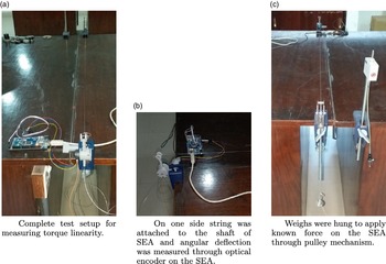
Torque linearity test setup for SEAs. Angle between moment arm (SEA shaft) and string was measured to calculate applied torque by SEA.

Bowden cable mechanism was implemented using plastic incision tubes (used in lung surgery) as sheath and fishing wire as internal pulling cable. This combination helped us in reducing the additional weight on the exoskeleton in comparison to traditional bowden cable assemblies available off the shelf. All parts and electronic circuitry used in fabrication and control of exoskeleton were commercially sourced. The actuation part of the exoskeleton is table mounted due to weight of actuators. However, this weight may be reduced in future versions by using light weight actuators in combination with an appropriate transmission.
All holes were kept with an internal diameter of 3 mm to keep parts symmetric. We used four stainless steel and six aluminum shafts to assemble the exoskeleton. We also installed 19 rotary stainless steel bearings with internal and external diameters of 3 and 6 mm, respectively. We installed four linear bearings to form two linear sliders over stainless steel shafts. Fabricated exoskeleton model is shown in Figs. 2 and 19.
4.6. Controller implementation
We used a cascaded control technique in which inner position controlled loop was cascaded with an outer admittance type controller. Inner loop rejected most of the mechanical plays and frictional effects running at 2.5 kHz. Individual joint control was implemented to control individual finger digits. The block diagram of feedback control loop is shown in Fig. 18. Virtual objects were implemented as an admittance given by Eq. (7):
 \begin{equation} A(s)=\frac{1}{Ms+B+K/s} \end{equation}
Here admittance
 $A(s)=\frac{\dot{X}(s)}{F(s)}$
and M, B, and K are mass, damping, and compliance of the virtual object, respectively.
5. Experimental Results
Experimental tests along with results are summarized in the subsequent sections.
5.1. Virtual fixture implementation
A virtual fixture was implemented to verify the performance of the device. The force law [Reference Desai, Gupta and Chakraborty58] for virtual fixture is defined by Eq. (8):
 \begin{equation} F_k=K(x_k-x_{\textrm{fixture}}) + B \dot{x} \end{equation}
Here K is the stiffness of fixture expressed in N/m and B (often used) is the damping coefficient of fixture. Figure 21 shows the generation of restoring vectors (shown in blue) as the exoskeleton is forced beyond the virtual fixture/object and will gently push the exoskeleton back inside the defined limits, thus assisting with rehabilitation therapy. Dotted line shows the position of end-effector and solid line shows the reference fixture location. This algorithm was planned to be implemented on the prototype exoskeleton, however, the implementation has currently been delayed due to COVID-19.
Force vectors generation beyond virtual fixture.

5.2. Workspace verification
We measured the covered workspace of our exoskeleton. Measurement results for MCP joint are shown in Fig. 26 and PIP joint are shown in Fig. 27. The maximum covered workspace by MCP joint was measured to be 46° where as that of PIP joint was 91°. This workspace varied with different human subjects.
SEA-1 torque linearity results. Graph shows the results of SEA-1 torque
 $\tau =K\theta$
versus
 $\tau =r \times F$
with RMSE = 0.0131 nm.

SEA-2 torque linearity results. Graph shows the results of SEA-2 torque
 $\tau =K\theta$
versus
 $\tau =r \times F$
with RMSE = 0.0195 nm.

Loop-1 inverse kinematics results. Solid line shows calculated position of SEA-1 angle whereas dotted line shows measured angle from installed rotary sensor.

Loop-2 inverse kinematics results. Solid line shows calculated position of SEA-2 angle whereas dotted line shows measured angle from installed rotary sensor.

Workspace verification for MCP joint.

5.3. Kinematic accuracy
We validated our model for kinematic accuracy using the installed positional sensors and physically measuring the MCP and PIP joint angles. Simultaneous data from SEA-1, SEA-2,
 $\theta _7$
, MCP, and PIP were recorded from kinematics model in addition to the physically measured angles at MCP and PIP joints. The estimates of MCP and PIP angles as obtained from the kinematic model and physical measurements were found to be coherent with each other with a tolerance of
 $\pm$
3°. This deviation can be accounted towards the measurement inaccuracies while physically measuring the joint angles. As the second kinematic chain is dependent on the first one, so a step wise solution was calculated. First the MCP chain was evaluated and was solved for MCP angle and then using the MCP angle PIP chain was solved for PIP angle. Measured angular positions are compared in Figs. 24 and 25 for both SEA-1 and SEA-2, respectively.
5.4. SEAs torque linearity and accuracy
We made a test setup where SEA was held on one side of the bench and on the other side known weights were hung to calculate the torque linearity and accuracy (Fig. 20). Data from positional encoder was used in conjunction with known spring constant, while the torque at the SEA was calculated using
 $\tau =K\theta$
. Similarly for each reading torque was also calculated using
 $\tau =r\times F$
. Results are shown in Figs. 22 and 23. Results from both the measurements show close conformity. The deviation in both results can be accounted against the measurement inaccuracies while physically measuring the angle between moment arm (r) and weight (F). The graphs with dotted line for both SEAs depict a fairly linear behavior.
5.5. Range of motion test
We tested and compared the device for covered ROM. We found that the covered ROM varied with the finger sizes of the user. We tested the device on two subjects with their prior consent. Results in comparison with previous SEA based exoskeletons reported in literature are tabulated in Table II. The covered ROM can be further increased by further tailoring the link lengths included in loop-1. For loop-2 complete range is covered as shown in the Table II.
6. Conclusion and Future Work
In this paper we have presented a novel design of index finger exoskeleton using SEAs comparable to previously reported exoskeletons. We kept the exoskeleton lightweight
 $\approx 240\ \textrm{g}$
with the provisioning of adjustability to various finger sizes of wearer. We have derived and tested the governing kinematic relations in comparison to a nonlinear simulation model followed by a fabricated prototype. We have presented an admittance type controller to control the interaction force of the end effector. The generation of virtual fixtures and virtual objects that can gently guide the wearer towards the required rehabilitation protocol has also been presented. We have carried out various tests to verify the validity of our designed and fabricated hardware. The progress on this work, specially the experimental validation of virtual fixtures/ objects has been delayed due to COVID-19 and will be continued as soon as it is practicable.
Range of motion comparison with similar exoskeletons

Workspace verification of PIP joint.

This device can be used as a rehabilitation device for people with affected physical movements of hands due to stroke or injury. For interaction with virtual reality a stiffer interaction would be required and we have kept the provisioning of replacing the stiffness elements without completely disassembling the device. Testing with different types of virtual objects can also be carried out. In future we intend to further reduce the size of our exoskeleton and extend it to control complete hand movements. Further ROM will be enhanced by carefully tweaking the link lengths of exoskeleton. We also plan to study, implement, and compare the results of other control techniques like impedance control and sliding mode control technique presented in the literature. We further plan to test the device in different rehabilitation scenarios in consultation with experienced physicians and improve on various aspects of the device.
Conflicts of Interest
None.
Financial Support
This research has been partially supported by National Technology Fund, IGNITE.
Ethical Considerations
None.
Authors’ Contributions
Design was conceived by HM. It was realized and modeled by HT and HM. Control System was designed by HM and modeled by HT. HH made substantial contributions to link lengths adjustment mechanism, encoder placement and ergonomics of design. UA made contributions towards design iterations of Series Elastic Actuation mechanism and spring placement. Kinematic Analysis was done by HT and critically analyzed by HM. Experimental and Simulation study was designed by HM and HT, and analysis/validation was performed by HT and UA. Interpretation of data was done by HM and HH. Paper was drafted by HT, reviewed critically for intellectual content by HM and finalized by HT and HM (HM = Hammad Munawar, HT = Hassan Talat, HH = Hamza Hussain, UA = Usama Azam).
Appendix
A.1. Loop-1 kinematic relations
From loop-1 closure equation 2 the calculated forward position (A1) and inverse position (A2) kinematic relations for loop-1 are as under:
 \begin{equation} A \tan ^2{\theta _1/2} + B \tan{\theta _1/2} + C = 0 \end{equation}
Here the quadratic equation (A1) outputs two possible values for MCP angle, one of which is a valid achievable position for the design. In this equation:
 \begin{align*} A & =-x_4+x_2\sin (\theta _2)+x_3\sin (\theta _3) \\[2pt] B & =2x_2\cos (\theta _2)+2x_3\cos (\theta _3) \\[2pt] C & =-x_4-x_2\sin (\theta _2)-x_3\sin (\theta _3) \end{align*}
Similarly the derived inverse position kinematic equation from Loop-1 closure equation is as under:
 \begin{equation} A \tan ^2{\theta _3/2} + B \tan{\theta _3/2} + C = 0 \end{equation}
Here quadratic equation (A2) solves for the position of required SEA-1 angle to achieve desired position of human finger. In this equation:
 \begin{align*} A & =-x_4+x_2\sin (\theta _1-\theta _2)-x_3\sin (\theta _1) \\[2pt] B & =-2x_3\cos (\theta _1) \\[2pt] C & =-x_4+x_2\sin (\theta _1-\theta _2)+x_3\sin (\theta _1) \end{align*}
By taking the derivative of loop-1 equation 2 we derived the velocity kinematics of loop-1. The derived forward and inverse kinematic relations are expressed by relations (A3) and (A4), respectively.
 \begin{equation} \omega _1=\frac{x_3\cos (\theta _1-\theta _3)}{x_2\cos (\theta _1-\theta _2)+x_3\cos (\theta _1-\theta _3)} \times \omega _3 \end{equation}
Here
 $\omega _1$
refers to angular velocity of MCP joint and
 $\omega _3$
refers to angular velocity of SEA-1 of exoskeleton.
 \begin{equation} \omega _3=\frac{x_2\cos (\theta _1-\theta _2)+x_3\cos (\theta _1-\theta _3)}{x_3\cos (\theta _1-\theta _3)}\times \omega _1 \end{equation}
A.2. Loop-2 kinematic relations
From Eq. (3) both forward and inverse kinematics relations were derived. Both these relations are expressed as under:
 \begin{equation} A \tan ^2{\theta _5/2}+ B \tan{\theta _5/2} + C = 0 \end{equation}
Here relations A, B, and C are as under:
 \begin{align*} A& =-x_4-x_7\sin (\theta _7-\theta _1)-x_8\sin (\theta _8-\theta _1) \\[2pt] &\quad -x_9\cos \theta _1-x_5\sin \theta _1\\[2pt] B& =2(-x_5\cos \theta _1+x_9\sin \theta _1) \\[2pt] C&=-x_4-x_7\sin (\theta _7-\theta _1)-x_8\sin (\theta _8-\theta _1)\\[2pt] &\quad +x_9\cos \theta _1+x_5\sin \theta _1 \end{align*}
Similarly the derived inverse position kinematic equation from Loop-2 closure equation is as under:
 \begin{equation} A \tan ^2{(\theta _8/2)} + B \tan{(\theta _8/2)} + C = 0 \end{equation}
Here relations A, B, and C are as under:
 \begin{align*} A &= -x_4+x_9\cos (\theta _1-\theta _5)-x_5\sin (\theta _5-\theta _1) \\[2pt] &\quad -x_7\sin (\theta _7-\theta _1)-x_9\sin \theta _1 \\[2pt] B & = 2(-x_8\cos \theta _1) \\[2pt] C & = -x_4+x_9\cos (\theta _1-\theta _5)-x_5\sin (\theta _5-\theta _1)\\[2pt] & \quad -x_7\sin (\theta _7-\theta _1)+x_9\sin \theta _1 \end{align*}
By taking the derivative of loop-2 Eq. (3) we derived the velocity kinematics of loop-2. The derived forward and inverse kinematic relations are expressed by relations (A7) and (A8), respectively.
 \begin{equation} \omega _5=\frac{A-B-C}{A}\times \omega _1+\frac{B}{A}\times \omega _7+\frac{C}{A}\times \omega _8 \end{equation}
 \begin{equation} \omega _8=\frac{-A+B+C}{C}\times \omega _1+\frac{A}{C}\times \omega _7-\frac{B}{C}\times \omega _8 \end{equation}
Here in both Eqs. (A7) and (A8) relations of A, B, and C are as under:
 \begin{align} A & =x_9\sin (\theta _1-\theta _5)-x_5\cos (\theta _5-\theta _1) \nonumber \\[2pt] B & =x_7\cos (\theta _7-\theta _1) \nonumber \\[2pt] C & =x_8\cos (\theta _8-\theta _1)\nonumber \\[2pt] D & = \frac{x_3\cos (\theta _1-\theta _3)}{x_2\cos (\theta _1-\theta _2)+x_3\cos (\theta _5-\theta _3)} \end{align}
A.3. Jacobian relations
We used the standard two link manipulator Jacobian available in literature [Reference Craig57].
 \begin{equation} J(\theta ) =\begin{bmatrix} -L_1\sin \theta _1-L_2\sin \theta _5 &\quad -L_2\sin \theta _5 \\ \\[-7pt] L_1\cos \theta _1+L_2\cos \theta _5 &\quad L_2\cos \theta _5 \end{bmatrix} \end{equation}
We substituted our derived relations into it to express the velocity Jacobian matrix in terms of exoskeleton joint angles which is as under:
 \begin{equation} J(\theta ) =\begin{bmatrix} f_1(D,\theta _1,\theta _5) &\quad -L_2\sin \theta _5\frac{B}{A} &\quad -L_2\sin \theta _5\frac{C}{A} \\ \\[-7pt] \,f_2(D,\theta _1,\theta _5) &\quad L_2\cos \theta _5\frac{B}{A} &\quad L_2\cos \theta _5\frac{C}{A} \end{bmatrix} \end{equation}
Definitions of
 $f_1(D,\theta _1,\theta _5)$
and
 $f_2(D,\theta _1,\theta _5)$
:
 \begin{align} f_1(D,\theta _1,\theta _5) &= -DL_1\sin \theta _1-DL_2\sin \theta _5 \nonumber \\[2pt] &\quad -DL_2\sin \theta _5\frac{A-B-C}{A}\nonumber \\[2pt] f_2(D,\theta _1,\theta _5) & = DL_1\cos \theta _1+DL_2\cos \theta _5 \nonumber \\[2pt] &\quad +DL_2\cos \theta _5\frac{A-B-C}{A} \end{align}
Pseudo-inverse of jacobian matrix was calculated where required given by:
 \begin{equation} J^{\dagger} = (J^T \times J)^{-1} \times J^T \end{equation}