I. INTRODUCTION
Recently, a considerable attention has been focused on the lithium metal alloys to meet ever increasing high energy density requirement for Li ion batteries. A special interest has been paid to Sn-based oxides since first reported by Idota et al.Reference Idota, Kubota, Matsufuji, Maekawa and Miyasaka1 that tin-based amorphous oxide (Sn1.0B0.56P0.40Al0.42O3.6) could yield a stable capacity over 600 mAh/g. A typical tin oxide, SnO2, can yield a theoretical capacity as high as 781 mAh/g with the reactions: SnO2 + 4Li → Sn + 2Li2O, Sn + xLi ↔ LixSn (x ≤ 4.4).Reference Courtney and Dahn2 Similar to Sn, Zn also showed a Li-storage ability by forming various Li–Zn alloys with a maximum LiZn composition (410 mAh/g).Reference Huggins3 A typical zinc-based material, ZnO, also exhibited reversible Li-storage ability.Reference Li, Huang and Chen4, Reference Wang, Pan, Cheng, Zhao and Yin5
Besides simple tin or zinc oxides, some mixed oxides such as ZnCo2O4,Reference Sharma, Sharma, Subba Rao and Chowdari6 ZnV2O4,Reference Xiao, Zhao, Yin and Zhang7 Co2SnO4,Reference Wang, Gao and Shen8 and ZnFe2O4Reference Guo, Lu, Fang, Mao, Wang, Chen, Xu, Yang and Liu9, Reference Fen, Yogesh and Snellius10 with the AB2O4 (or A2BO4) structure also show promising applications as anodes for Li ion batteries. The energy density and working voltage can be tuned by varying the A and B elements.Reference Lavela and Tirado11 These simple or mixed oxides, however, generally exhibit poor electrochemical performance due to the large volume changes upon Li uptake/release reactions. For example, the volume variation of Sn will reach as high as 358% during the Li uptake/release processes. Forming a composite with a matrix of Li inert or with less volume changes has been proved to be a practical strategy to alleviate the volume changes. Previous work showed that the mixed oxides could deliver a stable electrochemical cycling by loading them onto carbon matrices.Reference Deng, Zhang, Tang, Zhang, Deng, Shi and Chen12–Reference Wang, Liu and Liu14 The carbon materials are preferred as the matrices because they not only contribute to the overall capacity but also supply the electronically conducting channels, in addition to the strain buffering effect.
Zinc stannate (ZnSn2O4) is another mixed oxide as promising high capacity anode materials for Li ion batteries because both Zn and Sn are Li-active elements.Reference Belliard, Connor and Irvine15–Reference Zheng, Li, Xu, Hong and Wei17 ZnSn2O4 with cubic spinel structure is generally synthesized by high-temperature routes such as thermal evaporationReference Chen, Wang, Yu, Yang, Xie and Li18 and solid phase reactions.Reference Nikolić, Srećković and Ristić19 Compared with the high-temperature method, the hydrothermal route is more effective to obtain phase-pure product. The morphology of ZnSn2O4 could be easy to tune by adjusting the reaction conditions and/or using the additives such as mineralizer and coordinating agent.Reference Baruah and Dutta20 The electrochemical performance of ZnSn2O4, therefore, could be easily modified by varying the morphology such as using nanostructured materialReference Rong, Gao, Li, Yan, Zhu, Qu and Song16 or thin-layer coatingReference Zheng, Li, Xu, Hong and Wei17 during the hydrothermal reactions.
Herein, we report the one-pot synthesis of a Zn2SnO4/graphene (Zn2SnO4/G) hybrid through a facile in situ hydrothermal route. The graphene can be introduced via the in situ route since its precursor graphite oxide (GO) is processable in aqueous solution.Reference Li, Müller, Gilje, Kaner and Wallace21 The effects of graphene on the morphology and electrochemical performance of Zn2SnO4have been investigated.
II. EXPERIMENTAL
A. Preparation of Zn2SnO4/G hybrid
GO (60 mg), prepared by a modified Hummer’s method,Reference Hummers and Offeman22 was added into deionized (DI) water under sonication for 3 h to form a uniform solution. Then, 0.5 mmol of SnCl4·5H2O and 1 mmol of ZnSO4·7H2O were mixed in DI water and added slowly into the above solution with stirring for 2 h. NaOH was then introduced to reach a concentration of 0.4 mol/L. After being stirring for another 0.5 h, the mixed solution was transferred to a 100 mL Teflon-lined stainless steel autoclave and heated in an electric oven at 200 °C for 24 h. The resulting product was collected by centrifugation, washed with DI water and absolute ethanol for several times, and dried at 60 °C under vacuum overnight. For comparison, bare Zn2SnO4was synthesized with a similar route without adding GO.
B. Sample characterization
X-ray diffraction (XRD) patterns of the hydrothermal products were recorded on a Rigaku D/Max-2550PC powder diffractometer (Rigaku Industrial Corporation, Osaka, Japan) equipped with a Cu Kα radiation (λ = 1.541 Å). X-ray photoelectron spectroscopy (XPS) measurements were conducted on a KRATOS AXIS ULTRA-DLD spectrometer (Shimadzu Corporation, Kyoto, Japan) with a monochromatic Al Kα radiation (hv = 1486.6 eV). The field emission scanning electron microscopy (SEM) images were taken on a FEI-sirion microscope (Hitachi High Technologies America, Inc., Pleasanton, CA) and the transmission electron microscopy (TEM) and high-resolution transmission electron microscopy (HRTEM) images were taken on a JEM 2100F microscope (JEOL Ltd., Tokyo, Japan). Raman spectra were collected on a Jobin-Yvon Labor Raman HR-800 Raman system (HORIBA Jobin Yvon, Corporation Villeneuve d’Ascq, France) using a 514.5-nm Ar ion laser at 20 mW. Thermogravimetric (TG) analysis was carried out on a DSCQ1000 instrument (TA Instrument, Inc., New Castle, DE) from 29 to 800 °C at a ramp rate of 10 °C/min in air.
C. Electrochemical measurements
The electrochemical properties of the hydrothermal products (ZnSn2O4/G, ZnSn2O4) were measured using CR2025-type coin cells. ZnSn2O4/G (or ZnSn2O4), polyvinylidene fluoride, and acetylene black with a weight ratio of 75:15:10 were magnetically stirred in N-methyl pyrrolidone to form electrode slurry. The slurry was spread onto Ni foam and dried at 100 °C under vacuum for 10 h to make the working electrodes. The coin cells were assembled in an Ar-filled glove box using Li foil as the counter electrode and Celgard 2300 polypropylene microporous film (Celgard LLC Corporation, Charlotte, NC) as the separator. The electrolyte was composed of 1 M LiPF6 dissolved in ethylene carbonate/dimethyl carbonate with a volume ratio of 1:1. The cells were charged–discharged between 0.005 and 3 V (versus Li/Li+) at 50 or 200 mA/g on a Neware BTS-5V10 mA battery cycler (Neware Corporation, Shenzhen, China). Cyclic voltammetry (CV) test was performed on an Arbin BT2000 system (Arbin Instruments Corporation, College Station, TX) in the voltage range 0.005–3.0 V (versus Li/Li+) at 0.1 mV/s. All the electrochemical measurements were performed at 25 °C.
III. RESULTS AND DISCUSSION
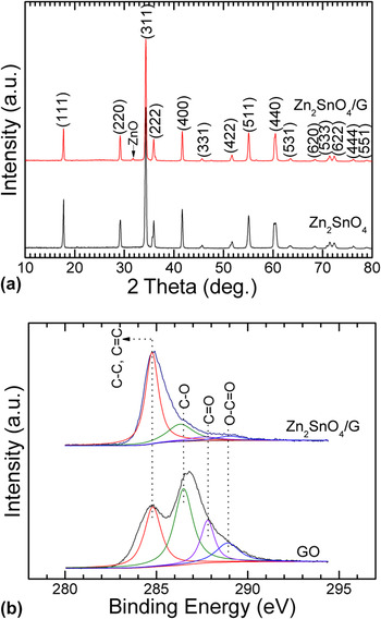
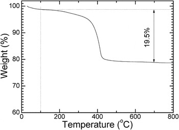
Figure 1(a) shows the XRD patterns of the hydrothermal products. The dominant diffraction peaks can be indexed to cubic Zn2SnO4 (space group Fd3m, JCPDS No. 74-2184) for both samples. For Zn2SnO4/G, the minor peak at 2θ = 32° is the (100) peak of ZnO. The characteristic peak of graphene (002) that should appear at 2θ = 25° is absent, implying that the direct restacking of the hydrophobic graphene reduced from hydrophilic GO has been inhibited due to the loading of the Zn2SnO4 crystals as the spacers. The graphene content in ZnFe2O4/G is estimated to be 19.5 wt% based on the TG analysis between 100 and 800 °C as seen in Fig. 2. The weight loss before 100 °C is due to the loss of the physically absorbed water in graphene.Reference Zhang, Zhu, Rui, Chen, Sim, Shi, Hng, Lim and Yan23 The sufficient exfoliation of the graphene sheets is thus confirmed since the relatively high graphene content will generally lead to the presence of the (002) peak of graphene.
(a) XRD patterns of Zn2SnO4/G and Zn2SnO4 and (b) C 1s XPS of Zn2SnO4/G and GO.

TG curve of Zn2SnO4/G.

The C 1s XPS spectra of Zn2SnO4/G and GO are shown in Fig. 1(b). The spectra can be deconvoluted into four peaks for four different carbons: nonoxygenated carbon (C–C, 285.6 eV, or C = C, 284.8 eV), carbon in C–O bonds (286.3 eV), carbonyl carbon (C = O, 287.6 eV), and carboxylate carbon (O–C = O, 289.0 eV).Reference Shin, Kim, Benayad, Yoon, Park, Jung, Jin, Jeong, Kim, Choi and Lee24 After the hydrothermal reactions, the peak intensity of the oxygenated carbons (C–O, C = O, O–C = O) demonstrates a remarkable reduction, suggesting the sufficient reduction of GO into graphene. From the XRD and XPS analyses, it can be concluded that a Zn2SnO4/G hybrid has formed during this facile one-pot hydrothermal process.
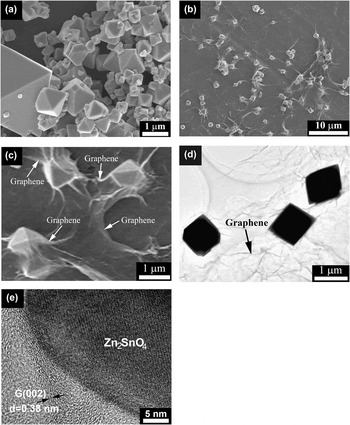
Figure 3(a) shows the SEM images of bare Zn2SnO4 prepared by the hydrothermal reactions at 200 °C for 24 h. The Zn2SnO4 particles exhibit an octahedral shape. However, it shows a rather wide size distribution with its size ranging from submicrometer to several micrometers. Microsized Zn2SnO4 octahedron was also obtained by Miyauchi et al.Reference Miyauchi, Liu, Zhao, Anandan and Hara25 using the hydrothermal route with NaOH as the mineralizer. Hydrothermal growth of Zn2SnO4 in the presence of NaOH occurs via the following reactionReference Zeng, Xin, Li, Wang, Yan and Zhang26:
 $${\rm{2Zn}}^{{\rm{2}} + } + {\rm{Sn}}^{{\rm{4}} + } + {\rm{8OH}}^ - \to {\rm{Zn}}_{\rm{2}} {\rm{SnO}}_{\rm{4}} + {\rm{4H}}_{\rm{2}} {\rm{O}}{\rm{\quad.}}$$
(a) SEM image of bare Zn2SnO4, (b) low-magnification SEM, (c) high-magnification SEM, (d) TEM images of Zn2SnO4/G, and (e) HRTEM of Zn2SnO4/G.

Mineralizer plays an important role in determining the morphology of the hydrothermal products. Zn2SnO4 nanorodsReference Zhu, Yang, Yu, Zhang, Jin and Yao27 and nanoparticlesReference Lana-Villarreal, Boschloo and Hagfeldt28 could be obtained when using N2H4·H2O and (CH3)4NOH, respectively, as the mineralizers.
Figure 3(b) shows the SEM image of the Zn2SnO4/G hybrid prepared by the in situ one-pot route. Note that the Zn2SnO4 crystals are confined by the graphene sheets. The wrinkles formed due to the incorporation of Zn2SnO4 crystal clearly indicate the presence of graphene. The wrinkles and the transparent nature also suggest that the graphene is rather thin composed probably of few-layer sheets. The Zn2SnO4 crystals in Zn2SnO4/G also exhibit octahedral shapes but with a much more homogeneous size distribution than bare Zn2SnO4. It seems that the introduction of graphene does not change the shape of the Zn2SnO4 crystals but improves their size homogeneity. It should be stressed that almost all the Zn2SnO4 crystals are uniformly dispersed and confined in between the graphene sheets. Namely, there are barely free Zn2SnO4 crystals even though they have a relatively large size. Without the confining effect, the Zn2SnO4 crystals tend to aggregation as shown in Fig. 3(a). Uniform dispersion of α-FeOOH was also realized by using graphene as the surfactant.Reference Zhang, Zhu, Rui, Chen, Sim, Shi, Hng, Lim and Yan23
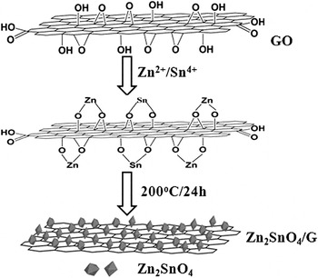
The magnified view of Fig. 3(b) is displayed in Fig. 3(c). It is clear that the Zn2SnO4 crystals with a size of around 1 μm are confined by graphene. There should be a strong interaction between Zn2SnO4 and graphene evidenced by the induced wrinkles. It can also be inferred that the graphene should have a high mechanical strength since the firm contact with the sharp edges of Zn2SnO4 crystals does not cause its rapture. In addition to its uniform size distribution, the Zn2SnO4 in Zn2SnO4/G also exhibits a perfect octahedral shape. By contrast, the octahedral morphology of bare Zn2SnO4 is not well defined. Namely, defects can always be observed in these crystals. This formed defects as well as the wide size distribution can be attributed to the dissolution–recrystallization process of the Zn2SnO4 crystals,Reference Zeng, Xin, Li, Wang, Yan and Zhang26 while in Zn2SnO4/G, the encapsulation effect of graphene may restrain the dissolution–recrystallization process of Zn2SnO4, leading to the uniform size distribution. It suggests that the interaction between Zn2+/Sn4+ and GO in the precursors also contributes to the homogeneous distribution of the final product. The TEM images in Fig. 3(d) clearly show that the size of the Zn2SnO4 octahedrons is about 1 μm. The transparent nature of the graphene also suggests that it is rather thin composed possibly of few-layer sheets, which is confirmed by HRTEM observation as indicated in Fig. 3(e). The formation mechanism of the Zn2SnO4/G hybrid is schematically illustrated in Fig. 4.
Schematic illustration of the formation mechanism of Zn2SnO4/G.

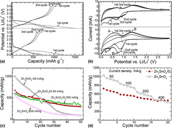
Figure 5(a) shows the voltage profiles of Zn2SnO4/G and Zn2SnO4 for the first three cycles charged–discharged at 50 mA/g. The specific capacity of Zn2SnO4/G is based on the total weight of Zn2SnO4 and graphene. The first charge (Li release) and discharge (Li uptake) capacities of bare Zn2SnO4 are 1007 and 1521 mAh/g, respectively. The reactions of Zn2SnO4 with Li can be written asReference Rong, Gao, Li, Yan, Zhu, Qu and Song16:
 $${\rm{8Li}}^ + + {\rm{Zn}}_{\rm{2}} {\rm{SnO}}_{\rm{4}} + {\rm{8e}}^ - \to {\rm{2Zn}} + {\rm{Sn}} + {\rm{4Li}}_{\rm{2}} {\rm{O\quad,}}$$
 $$x{\rm{Li}}^ + + {\rm{Sn}} + x{\rm{e}}^ - \lleftrightarrow {\rm{Li}}_x {\rm{Sn,}}\,{\rm{ 0}} \,\le\, x \,\le\, {\rm{4}}{\rm{.4\quad,}}$$
 $${\rm{Li}}^ + + {\rm{Zn}} + y{\rm{e}}^ - \lleftrightarrow {\rm{Li}}_y {\rm{Zn, }}\,{\rm{0}} \,\le \,y \,\le {\rm{1}}{\rm{\quad.}}$$
(a) Charge–discharge curves of Zn2SnO4/G and Zn2SnO4 at 50 mA/g, (b) CV plots of Zn2SnO4/G and Zn2SnO4 at 0.1 mV/s, (c) cycling performance of Zn2SnO4/G and Zn2SnO4 charged at 50 or 200 mA/g and discharged at 50 mA/g, and (d) rate capability of Zn2SnO4/G and Zn2SnO4.

Based on the above reaction mechanism, the theoretical capacity of Zn2SnO4 is around 547 mAh/g. The higher obtainable capacity is possibly due to the reversible reactions (at least partly) of Eq. (2), which corresponds to the quasiplateau at around 1.5 V. The large first irreversible capacity is related to the irreversible formation Li2O and/or the formation of solid electrolyte interface layer. The large first capacity loss has been proved to be solvable by many strategies,Reference Ji, Ma and Lee29 e.g., prelithiation method.Reference Seonga, Kim and Yoon30 Compared with bare Zn2SnO4, Zn2SnO4/G shows a lower charge capacity of 674 mAh/g and also a lower discharge capacity of 1223 mAh/g. The relatively low capacity can be attributed to the incorporation of graphene with a low capacity as reported in our previous work.Reference Liu, Xie, Zheng, Cao, Zhu and Zhao31
Figure 5(b) gives the CV plots of Zn2SnO4/G and Zn2SnO4 scanned at 0.1 mV/s. Two couples of redox peaks can be observed in Fig. 5(b). The first couple (A and A′) corresponds to the alloying/dealloying of Sn and Zn.Reference Huggins3 The second couple (B and B′) is related to the reversible Eq. (2) as mentioned above. For Zn2SnO4/G, apart from the first scan, the plots are almost overlapped during the subsequent scans, indicating the high reversibility of the electrode. In contrast, for bare Zn2SnO4, the peak intensity of the plots is on the increase, suggesting that it is undergone an activation process. It suggests that the improved reversibility of Zn2SnO4/G is ascribed to the introduction of graphene, which has been intensively investigated as the promising building block to form composites due to its large specific surface area,Reference Stoller, Park, Zhu, An and Ruoff32 high mechanical strength,Reference Lee, Wei, Kysar and Hone33 high electronic conductivity,Reference Park, An, Jung, Piner, An, Li, Velamakanni and Ruoff34 and the many-electron effectReference Liang, Huang and Yang35 since first reported by Novoselov et al.Reference Novoselov, Geim, Morozov, Jiang, Zhang, Dubonos, Grigorieva and Firsov36
Figure 5(c) compares the cycling stability between Zn2SnO4/G and Zn2SnO4. The cells are charged at 50 and 200 mA/g and discharged at 50 mA/g. Obviously, Zn2SnO4/G demonstrates an enhanced cycling stability compared with bare Zn2SnO4. After being charged at 200 mA/g for 50 cycles, Zn2SnO4/G can still retain a charge capacity of 326 mAh/g, while for bare Zn2SnO4, the capacity drops rapidly to 100 mAh/g after the same cycles. The enhanced cycling stability can be attributed to the incorporated graphene, which not only effectively buffers the large volume variations but also confines Zn2SnO4 crystals. Note that Zn2SnO4/G exhibits a similar cycling performance when cycled at 50 and 200 mA/g due to the effective conducting and dispersing effects of graphene. This is often observed for the graphene-based composites. Good cycling stability could be realized by using nanosized particles.Reference Rong, Gao, Li, Yan, Zhu, Qu and Song16 The electrochemical performance of our sample is comparable with the work by Rong et al.Reference Rong, Gao, Li, Yan, Zhu, Qu and Song16 even though the particle size of our sample is at the micrometer scale due to the effective buffering and confining effect of the in situ introduced graphene. Improved cycling stability is also observed by forming a Zn2SnO4/C composite, which can keep a capacity over 400 mAh/g after 40 cycles at 60 mA/g.Reference Yuan, Tian and Liu37 Similarly, increasing acetylene black ratio in the composite could also improve the cycling stability of Zn2SnO4, where a capacity of 689 mAh/g is remained after 50 cycles at 50 mA/g.Reference Hou, Cheng, Bai and Zhang38 As reported by Feng et al.,Reference Feng, Peng, Sun, Qiao, Li, Wang, Hu and He39 stable cycling was achieved for Zn2SnO4 by using monodisperse single crystal cubes, which could yield a capacity of 775 mAh/g after 20 cycles at 50 mA/g. Figure 5(d) compares the rate capability between Zn2SnO4/G and Zn2SnO4. Although bare Zn2SnO4 can yield a higher capacity than Zn2SnO4/G, its capacity change is more sensitive to the current change than that of Zn2SnO4/G. At 400 mA/g, the capacity of Zn2SnO4/G even surpasses that of Zn2SnO4, even though Zn2SnO4/G has a much lower theoretical capacity than bare Zn2SnO4. The improved rate capability can be attributed to the synergy between Zn2SnO4 and graphene. On one hand, graphene affords two-dimensional (2D) conductive networks for the Zn2SnO4 crystals and disperses Zn2SnO4 crystals uniformly. On the other hand, the Zn2SnO4 particles can act as spacers to prevent the direct restacking of the graphene sheets. Such a hybrid structure is favorable for maximizing the contact with the electrolyte for both Zn2SnO4and graphene, leading to rapid Li ion diffusion both at the electrode–electrolyte interface and within the bulk electrode. As a result, electrode kinetics can be remarkably enhanced by graphene incorporation.
IV. CONCLUSIONS
In summary, a Zn2SnO4/G hybrid has been synthesized by a facile in situ one-pot hydrothermal method. The Zn2SnO4 crystals exhibit a well-defined octahedron shape with a size around 1 μm. Compared with bare Zn2SnO4, Zn2SnO4 in Zn2SnO4/G shows a narrower size distribution due to the inhibited dissolution–recrystallization confined by graphene. The Zn2SnO4/G hybrid shows better cycling stability and rate capability than bare Zn2SnO4. The enhancement in cycling stability is attributed to the introduction of the flexible graphene that serves both as the buffer to alleviate the volume changes and as the separator to restrain the crystal aggregation of Zn2SnO4. The introduction of the graphene also offers 2D conductive networks for Zn2SnO4and maximizes their contact with the electrolyte, leading to the enhanced electrode kinetics and thus improved rate capability.
ACKNOWLEDGMENTS
This work was supported by the National Natural Science Foundation of China (Grant No. 51101139), the Ph.D. Programs Foundation of Ministry of Education of China (Grant No. 20100101120024), the Foundation of Education Office of Zhejiang Province (Grant No. Y201016484), the Qianjiang Talents Project of Science Technology Department of Zhejiang Province (Grant No. 2011R10021), and Key Science and Technology Innovation Team of Zhejiang Province under Grant No. 2010R50013.