Introduction
In recent years, with the rapid development of detection technology, there have been increasingly stringent requirements for both radar detection range and stealth performance [Reference Sang, Xu, Liu, Mei, Wang and Shen1]. High-gain, ultra-wideband, and low-radar cross-section (RCS) antennas not only contribute to extending the radar detection range but also play a critical role in improving stealth capability. Therefore, the design and development of such antennas have attracted extensive research attention and are considered to be of great significance for practical applications in modern radar and communication systems.
The Fabry–Perot antenna (FPA), as a typical high-gain antenna, can achieve significant gain enhancement without the need for large-scale arrays or complex feeding networks. However, its 3-dB gain bandwidth is relatively narrow, with early designs typically limited to only 3%–5% [Reference Feresidis and Vardaxoglou2, Reference Weily, Esselle, Sanders and Bird3]. It has been demonstrated that introducing an all-dielectric partially reflective surface (PRS) structure can effectively broaden the gain bandwidth [Reference Baba, Hashmi, Esselle and Weily4, Reference Lalbakhsh, Afzal, Esselle, Smith and Zeb5]. For instance, in [Reference Lalbakhsh, Afzal, Esselle and Smith6], a 3-dB gain bandwidth of up to 41% was achieved by employing this method, which utilizes multiple types of dielectric materials with a transverse gradient of effective permittivity. Nevertheless, this approach suffers from high design complexity and manufacturing costs. In [Reference Leszkowska, Rzymowski, Nyka and Kulas7] reported adding parasitic patches onto a dielectric PRS to modulate the phase distribution and enhance broadband gain, but did not consider RCS reduction. Moreover, the all-dielectric PRS structure has rarely been considered for RCS reduction purposes.
Various approaches have been proposed to reduce the RCS of antennas, including absorbing surfaces [Reference Yu, Jiang and Gong8–Reference Zhang, Li, Jin, Lv and Mittra10], coded surfaces [Reference Zhang11, Reference Liu, Zhang, Jia and Wu12], artificial magnetic conductors (AMCs) [Reference Cheng, Yang, Zhong, Liao and Ding13–Reference Xing, Yang, Yang and Yang16], and checkerboard metasurfaces [Reference Jia, Liu, Zhang, Wang, Gong and Liao17–Reference Guo, Wang, Hao, Huang, Gong and Song23]. Among them, absorbing surfaces can effectively attenuate incident electromagnetic waves to achieve RCS reduction [Reference Yu, Jiang and Gong8–Reference Zhang, Li, Jin, Lv and Mittra10]. However, this method usually degrades the antenna radiation performance, such as gain. In [Reference Zhang11], a coded metallic surface was employed to reduce the RCS, but the antenna exhibited a limited 3-dB gain bandwidth of only 4.8%. In addition, checkerboard metasurface array antennas based on polarization conversion have been utilized to achieve RCS reduction [Reference Gao, Yan, Jie and Hua19–Reference Li, Liu, Jia and Guo22]. Nevertheless, their bandwidth performance is highly dependent on the complexity of the feeding network. For example, the design in [Reference Wang, Jia, Hu, Liu, Lei, Sun and Cui20] used the polarization conversion metasurface (PCM) both as a scatterer and radiator in an antenna array, achieving a 21.6% 3-dB gain bandwidth, which inevitably increased the difficulty of feeding network design. Recently, PCMs, AMCs, and frequency selective surfaces (FSSs) have been widely adopted to reduce the RCS of FPAs by leveraging phase cancellation mechanisms, while simultaneously improving antenna gain [Reference Cheng, Yang, Zhong, Liao and Ding13, Reference Liu, Yan, Wang, Zhang and Fan15, Reference Huang and Fan18, Reference Li, Liu, Jia and Guo22]. However, some technical challenges remain. For instance, the AMC design in [Reference Liu, Yan, Wang, Zhang and Fan15] employs a complex five-layer structure to achieve RCS reduction, significantly increasing design complexity and manufacturing cost. The work in [Reference Cheng, Yang, Zhong, Liao and Ding13] also relies on multi-layer structures, resulting in a narrow gain bandwidth. Furthermore, the RCS reduction bandwidth achieved in PCM-based designs is often limited, with the designs in [Reference Huang and Fan18, Reference Li, Liu, Jia and Guo22] achieving only about 80% bandwidth. [Reference Zheng, Gao, Zhou and Cao24] reported a FSS-based PRS to improve FPA gain and reduce antenna RCS, but the RCS reduction performance was suboptimal, achieving a 76.92% RCS reduction bandwidth (8-18 GHz). [Reference Liu, Liu, Zhao, Kong, Huang and Bian25] employed a FSS-based superstrate with a positive slope reflection phase to achieve broadband gain enhancement and RCS reduction via destructive interference between the retransmitted waves and the reflected waves. However, limited by the number of reflections within the cavity, only a 54.55% (8.6 to 14 GHz) RCS reduction bandwidth was achieved. Therefore, achieving an FPA with ultra-wideband RCS reduction while maintaining stable, broadband, and high-gain performance remains a significant challenge.
In this paper, a novel hybrid metasurface is proposed to simultaneously enhance the 3-dB gain bandwidth of the FPA and achieve ultra-wideband RCS reduction. Specifically, a checkerboard-type PCM with a high polarization conversion ratio (PCR) is employed to effectively reduce the RCS of the FPA. Furthermore, by introducing a nonuniform reflective metasurface with a positively sloped reflection phase beneath the PCM, the proposed design not only improves the antenna gain but also significantly broadens the 3-dB gain bandwidth, while maintaining stable gain performance within the operating band. It also improves the electric field distribution at the FPA aperture, enhancing aperture illumination uniformity. The remainder of this paper is organized as follows. Section II presents the antenna configuration and analyzes its operating mechanisms. Section III provides the fabrication, measurement, and discussion of the antenna performance. Finally, Section IV draws the conclusion.
Antenna design and working principle analysis
Configuration and analysis of the polarization conversion
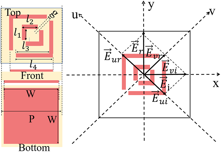
As illustrated in Fig. 1, a hybrid metasurface is strategically designed, where the metasurface is positioned directly beneath the PCM cell. The structure consists of a PCM cell integrated with a metasurface layer, and is implemented on an F4B dielectric substrate with a relative permittivity of  $\varepsilon_r = 2.2$ and a loss tangent of
 $\tan\theta = 0.004$, with a thickness denoted by
 $t_1$. The bottom and top layers comprise a continuous metallic ground plane and a symmetric double L-shaped metallic patch, respectively.
Configuration of the proposed hybrid metasurface unit cell.

The PCM cell features a configuration whose principal axes (u- and v-axes) are oriented at 45 $^{\circ}$ with respect to the Cartesian x- and y-axes. Due to the anisotropic nature of the cell – namely, the differing resonant responses along the u- and v-directions – a phase difference is introduced between the two components.
Assuming that the incident wave  $\vec{E_\mathrm{i}}$ is a normally incident x-polarized electromagnetic wave, it can be decomposed into two orthogonal components along the diagonal directions of the unit cell, namely the u- and v-directions. The corresponding electric field amplitudes are given by:
 \begin{equation}
\vec{E}_{\mathrm{i}}=\vec{\mathrm{u}} \vec{E}_{\mathrm{u i}}+\vec{\mathrm{v}} \vec{E}_{\mathrm{v i}}
\end{equation}
The electromagnetic intensity  ${E}_\mathrm{r}$ of the reflected electromagnetic wave can be expressed as:
 \begin{equation}
\vec{E}_{\mathrm{r}}=\vec{\mathrm{u}} \vec{E}_{\mathrm{ur}}+\vec{\mathrm{v}} \vec{E}_{\mathrm{vr}}=\vec{\mathrm{u}} \,\vec{r}_{\mathrm{u}} {E}_{\mathrm{ui}}{e}^{{j}\varphi}+\vec{\mathrm{v}}\,\vec{r}_{\mathrm{v}} {E}_{\mathrm{vi}}{e}^{{j} \varphi}
\end{equation}
 $\vec{E}_\mathrm{ui}$ and
 $\vec{E}_\mathrm{vi}$ denote the components of the incident electric field along the
 $\vec{\mathrm{u}}$ and
 $\vec{\mathrm{v}}$ directions, respectively.
 $\varphi$ represents the phase of the incident electromagnetic wave.
 $\vec{E}_\mathrm{r}$ is the electric field amplitude of the reflected wave, while
 $\vec{E}_\mathrm{ur}$ and
 $\vec{E}_\mathrm{vr}$ are the reflected electric field components in the
 $\vec{\mathrm{u}}$ and
 $\vec{\mathrm{v}}$ directions, respectively. The terms
 $\vec{r}_\mathrm{u}$ and
 $\vec{r}_\mathrm{v}$ denote the reflection coefficients along the
 $\vec{\mathrm{u}}$ and
 $\vec{\mathrm{v}}$ directions. According to the above relations, when the polarization direction of the reflected wave is rotated to the y-polarization, the phase difference between the two components is given by
 $\Delta\varphi = \varphi_v - \varphi_u = 180^\circ$.
The PCR is defined as,
 \begin{equation}
\mathrm{PCR}=\frac{r_{x y}^{2}}{\mathrm{r}_{\mathrm{xx}}^{2}+\mathrm{r}_{\mathrm{xy}}^{2}}
\end{equation}
where the cross-polarized electric field reflection coefficient  $r_{xy}$ and the co-polarized electric field reflection coefficient
 $r_{xx}$ are,
 $r_{x y}=\left|\frac{E_{r}^{x}}{E_{i}^{y}}\right|$,
 $r_{x x}=\left|\frac{E_{r}^{x}}{E_{i}^{x}}\right|$.
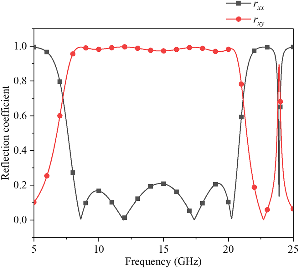
According to the analysis presented above, a simulation was performed using CST Studio Suite using Floquet ports and unit boundary conditions to obtain the reflection coefficient of the hybrid metasurface. The reflection phases of the PCM under different sizes of metasurface were explored. As illustrated in Fig. 2, four resonance modes are excited at 8.6, 11.9, 17.36, and 20.24 GHz in the proposed hybrid metasurface, enabling ultra-wideband polarization conversion from 7.7 GHz to 20.7 GHz.
Reflection coefficient of the PCM unit when incident waves propagate along the -z-direction under W = 10 mm.

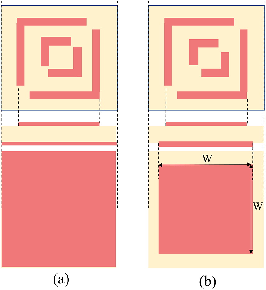
To simultaneously achieve polarization conversion and energy transmission, the metasurface (see Fig. 3(a)) is modified by reducing the size of the square elements on the bottom layer. This adjustment creates gaps between adjacent units in the planar layout, allowing energy to be transmitted through them, thereby forming an integrated metasurface with both reflection and transmission functionalities (see Fig. 3(b)). As can be seen from Fig. 4, the proposed hybrid metasurface demonstrates excellent PCR across six different metasurface sizes within the frequency range of 7.8–21.1 GHz. The ultra-wideband characteristic can be verified by the surface current distributions shown in Fig. 5. As observed from the figure, the current distributions on the upper and lower surfaces for resonance modes 1, 2, and 3 are in opposite directions, forming a current loop. Therefore, these three modes are magnetic resonances. In contrast, the currents on the upper and lower surfaces of the metasurface in mode 4 are in the same direction, indicating an electric resonance. As a result, all four resonance modes are simultaneously excited, obtaining an ultra-wideband polarization conversion.
Evolution of hybrid metasurface unit cell. (a) Reflective hybrid metasurface unit cell, (b) Proposed hybrid metasurface unit cell.

PCR of PCM unit under different sizes (W) of metasurface.

Surface current distributions of the proposed hybrid metasurface at resonant modes.

On the other hand, the phase difference of the proposed hybrid metasurface element along the u- and v-directions is investigated. As shown in Figs 6 and 7, A phase difference of approximately 180 $^{\circ}$ (
 $\pm$37
 $^{\circ}$) is achieved along the u- and v- directions, except for phase discontinuities that occur near 10 GHz. It should be noted that these phase discontinuities do not affect the RCS reduction bandwidth. Therefore, it can be concluded that the ultra-wideband polarization conversion function is realized by the proposed hybrid metasurface.
Reflection phases of the PCM unit under different W. W is the size of the proposed metasurface. (a) Under u direction, (b) Under v direction.

Phase difference between the U and V directions of the PCM unit under different W.

According to the theory of arrayed RCS reduction (RCSR) can be expressed as [Reference Gao, Yan, Jie and Hua19],
 \begin{equation}
\mathrm{RCSR}=10 \cdot \log \left|\frac{E_{r}^{2}}{E_{i}^{2}}\right|=10 \cdot \log (1-\mathrm{PCR}) \leq-10 dB
\end{equation}
From Eq. (4), it can be concluded that when the PCR of the PCM unit is greater than 0.9, the chessboard-like metasurface composed of these units can achieve an RCS reduction of more than 10 dB.
Therefore, based on the above analysis, the proposed metasurface can theoretically achieve ultra-wideband RCS reduction simply by using a chessboard-like layout. Its bandwidth ranges from 7.7 to 20.7 GHz, corresponding to the bandwidth of the proposed hybrid metasurface.
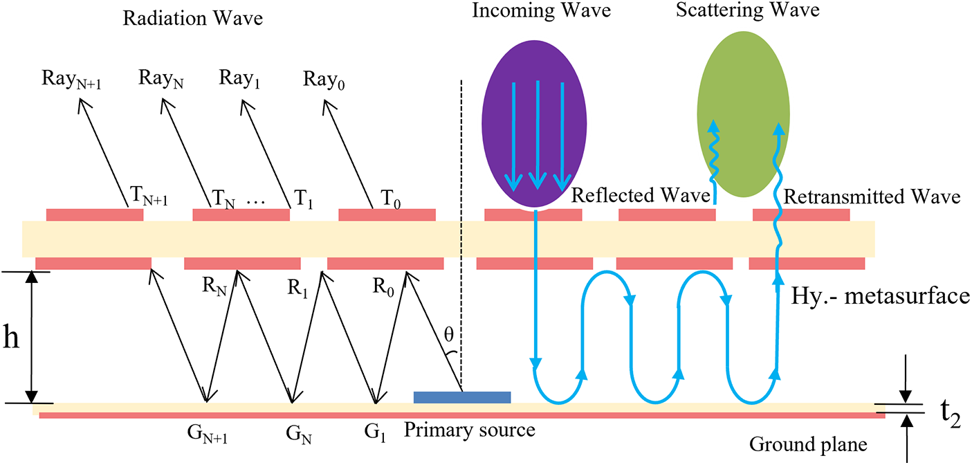
As shown in Fig. 8(a), the checkerboard PCM consists of four PCM modules arranged mirror-symmetrically. When an incident wave propagates along the +Z-direction toward the checkerboard PCM, most of the incident wave is reflected by the PCM, enabling coherent cancellation. A small portion of the electromagnetic wave transmits through the hybrid metasurface into the cavity. After multiple reflections ( $q$ times) within the cavity, the wave retransmits out as shown in Fig. 9. Ignoring losses, the total electric field can be expressed as [Reference Liu, Liu, Zhao, Kong, Huang and Bian25]:
 \begin{equation}
E_\text{tot} = E_r + E_t
\end{equation}
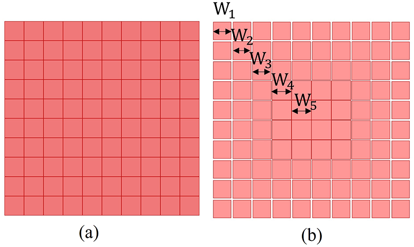
Configuration of the proposed antenna. (a) Checkerboard PCM, (b) Nonuniform reflective metasurface. The unit cell of the proposed metasurface from the center to the edge, the sizes are  $m$=20,
 $n$=12,
 $W_5$ = 9.95,
 $W_4$ = 9.8,
 $W_3$ = 9.5,
 $W_2$ = 9.2,
 $W_1$ = 8.95 (units:mm), (c) Feeding antenna
 $n_1$=10.52,
 $n_2$=9.92,
 $d_1$=7,
 $d_2$=5.8,
 $s$=0.7 (units:mm).

where  $E_r$ represents the reflected electric field, and
 $E_t$ represents the transmitted electric field through the hybrid metasurface.
The reflected electric field from the checkerboard PCM is:
 \begin{equation}
E_r= 2E_{ra} \left( r_{xx} e^{-j\varphi_1} + r_{xy} e^{-j\varphi_2} \right)
\end{equation}
 \begin{equation}
\quad\qquad + 2E_{ra} \left( r_{xx} e^{-j\varphi_3}+ r_{xy} e^{-j\varphi_4} \right)
\end{equation}
where  $E_{ra}$ is the reflection amplitude of each PCM module,
 $\varphi_1$,
 $\varphi_2$,
 $\varphi_3$, and
 $\varphi_4$ denote the reflection phases of different components from different PCM modules. When the phases of the checkerboard PCM modules are designed such that
 $\varphi_1=\varphi_3$ and
 $\varphi_1-\varphi_4=\pm 180^\circ$, Eq. (6) simplifies to:
 \begin{equation}
E_r = 4E_{ra} r_{xx} e^{-j\varphi_1}
\end{equation}
Equation (7) shows that the cross-polarization components cancel out, leaving only the co-polarized reflection. The designed PCM unit exhibits a cross-polarization reflection coefficient greater than 90% over a broad band (7.7–20.7 GHz). The array symmetry further promotes cancellation of cross-polarized scattering while suppressing co-polarized reflection, thereby reducing monostatic RCS.
The transmitted field after  $q$ reflections inside the cavity transmits through the proposed metasurface again along the +z-direction and forms the retransmitted electric field
 $E_{tq}$.
 \begin{equation}
E_{tq} = E_{tqa} e^{j\left[ (q+1)\phi_T + (q-1)\phi_R + q\phi_G + 2q h K \right]}\
\end{equation}
where  $E_{tqa}$ is the amplitude of the transmitted field,
 $\phi_{\mathrm{T}}$,
 $\phi_{\mathrm{R}}$ and
 $\phi_{\mathrm{G}}$ represent the transmission, reflection phases of the proposed hybrid metasurface and the ground, respectively,
 $K$ is the wave number and
 $h$ is the height of the FPA cavity. The total transmitted field is:
 \begin{equation}
E_t = \sum_{q=1}^{\infty} E_{tq}\
\end{equation}
The phase difference between the wave retransmitted after  $q$ times reflections and the incident wave is:
 \begin{equation}
\Delta\phi _{\mathrm{phase}}=(q+1)\phi_{\mathrm{T}} +(q-1)\phi_{\mathrm{R}}+q\phi_{\mathrm{G}}+2qhK\
\end{equation}
When the phase difference between the retransmitted waves and the reflected waves is within the range of 180 $^{\circ}$
 $\pm$ 37
 $^{\circ}$, destructive interference occurs between the retransmitted wave and the reflected wave, further reducing the RCS.
The working principles of ultra-wideband low RCS stable-gain FPA
The proposed FPA, shown in Fig. 8, consists of a feeding antenna, checkerboard-type PCM with a high reduction in RCS, and a nonuniform reflective metasurface that can perform the reflection and transmission functions for cavity electromagnetic waves. The feeding antenna is fed by a coaxial probe and features a patch antenna with a U-shaped slot etched on the radiating patch to enhance the operating bandwidth. The U-shaped patch antenna is etched on the upper surface of an F4B plate, with the lower surface serving as a ground plane. The second component is a 1-bit PCM checkerboard array, which is designed to reduce the RCS of the FPA. Additionally, to increase the gain of the FPA and maintain gain stability, a nonuniform reflective metasurface is strategically arranged to form a hybrid metasurface. This hybrid surface is employed for electromagnetic wave cancellation, thereby achieving RCS reduction, while the lower surface is a nonuniform partially reflective surface that exhibits partial reflection properties. The key dimensions of the proposed FPA are listed in Table 1.
Key dimensions of the proposed FPA (units: mm)

The working principle of the FPA is shown in Fig. 9. Let the electric field amplitude of the primary source be  $E_p$ and the radiation angle be
 $\theta$. Then the electric field amplitude of the
 $\ Ray_N$ can be expressed as [Reference Lian, Tang and Yin26]:
 \begin{equation}
E_N = E_p \cdot \left( \prod_{i=0}^{N-1} R_i \right) \cdot T_N
\end{equation}
Hybrid metasurface working schematic (h=20.3 mm;  $t_2$=1.5 mm). Hy.- metasurface: Hybrid metasurface.

where  $T_N$,
 $R_N$ are the transmission coefficient amplitude and reflection coefficient amplitude, respectively, satisfying:
 \begin{equation}
R_N^2 + T_N^2 = 1
\end{equation}
To achieve a uniform amplitude distribution across the aperture, i.e.,  $E_{N+1} = E_N$ The relationship between
 $R_N+1$ and
 $R_N$ can be derived from Eqs. (11) and (12) as:
 \begin{equation}
R_{N+1} = \sqrt{\frac{2 R_N^2 - 1}{R_N^2}}
\end{equation}
From Eqs. (11) and (13), with the increase of the number of reflections  $N$, the aperture electric field amplitude
 $E_\mathrm{N}$ decreases exponentially. In order to prevent the electric field amplitude from decreasing too fast, the electric field amplitude should be compensated, and the
 $R$ should be reduced from the center to the edge, which is conducive to the equal amplitude distribution of the electromagnetic wave inside the aperture, and improves the 3-dB gain bandwidth of the FPA.
To superimpose multiple reflected and transmitted electromagnetic waves in the same phase, the phase difference between any two neighboring beams  $Ray_{N+1}$ and
 $Ray_N$ after transmission is
 $2\alpha\pi$ (
 $\alpha = 0,\pm 1,2,3 \cdots$) [Reference Xing, Yang, Yang and Yang16],
 \begin{align}\phi_{\mathrm{N+1}}&=\phi_{\mathrm{RN}} +\phi_{{\mathrm{G}}(\mathrm{~N}+1)}+\phi_{\mathrm{{T}}(\mathrm{~N}+1)}- \phi_{\mathrm{{T}}\mathrm{N}} \nonumber\\
&\quad -K\cdot 2h\cos\theta +K\cdot 2h\tan \theta \sin \theta =2 \alpha \pi\end{align}
The reflection phase of the designed overlay can be expressed as [Reference Zhang11],
 \begin{equation}
\phi_{\mathrm{HM}} =4 \pi h / \lambda-\phi_{\mathrm{G} }+ 2 \alpha \pi
\end{equation}
where  $\phi_{\mathrm{HM}}$ represent the reflection phases of the proposed hybrid metasurface and
 $\lambda$ is the wave length. The directional coefficient of the FPA is [Reference Zhang11],
 \begin{equation}
D=10 \log \left(\frac{1+R}{1-R}\right)
\end{equation}
 $R$ is the reflection amplitude of the overlay.
From Eqs. (15) and (16), a larger reflection magnitude R leads to higher directivity and gain. The reflection phase slope of the superstrate being close to ( $4\pi h/c$ ) over a wide bandwidth enables the excitation of the FPA’s resonant modes within that band. Therefore, in order to realize the high gain of FPA with a wide bandwidth, the reflection phase of the reflective layer should be designed as a positive slope reflection phase, and the reflection amplitude should be as large as possible in the desired operating frequency band, simultaneously.
Based on the above mechanism, this paper designs five FSS unit cells with different sizes. The reflection characteristics of the proposed nonuniform reflective metasurface unit cells with varying sizes were simulated and analyzed. As shown in Fig. 10, the FSS composed of five different-sized unit cells exhibits a positive slope reflection phase. The reflection phase increases positively with frequency within the range 7.2-8.6 GHz, with a slope value near  $4\pi h/c$ around 8 GHz. The reflection amplitude (corresponding to
 $R$ in Eqs. (13) and (16) for these five FSS unit cells are 0.95, 0.88, 0.77, 0.68, and 0.6, respectively. The proposed nonuniform reflective metasurface and a reference metasurface are shown in Fig. 11. The five FSS unit cells of different sizes are distributed on the lower surface of the superstrate, arranged concentrically from the center toward the edges, as depicted in Fig. 11(b). The
 $R$ value gradually decreases from the center outwards. At the center of the proposed nonuniform reflective metasurface, the FSS reflection unit has the maximum
 $R$ (0.95) and the minimum reflection order
 $N$, resulting in the highest aperture field magnitude. At the edge of the proposed nonuniform reflective metasurface, the reflection order
 $N$ is maximum, and
 $R$ is reduced to 0.6, The gradient-varying reflection amplitude
 $R$ counteracts the edge field attenuation resulting from multiple reflections, preventing the field magnitude from decaying too rapidly, thus enabling a more uniform aperture field distribution (Fig. 14(c)). Compared to the uniform reflective metasurface, the proposed nonuniform reflective metasurface significantly improves the electric field distribution across the antenna aperture, making it more uniform and enhancing the antenna’s broadband radiation performance.
(a) Reflection phase and (b) reflection coefficient of the proposed nonuniformly metasurface unit when incident waves propagate along the +z-direction.

Evolution of the metasurface. (a) Uniform reflective metasurface, (b) Proposed nonuniform reflective metasurface.

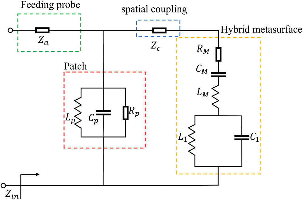
In order to effectively characterize the resonant properties of the proposed FPA, an equivalent circuit model of the proposed FPA is presented in Fig. 12. This model incorporates both the fed patch antenna and the hybrid metasurface. The fed antenna is implemented as a patch structure with a U-shaped slot. Its equivalent circuit can be represented by a parallel RLC resonant circuit, where  $C_p$,
 $L_p$, and
 $R_p$ denote the equivalent capacitance, inductance, and radiation resistance of the U-slot patch, respectively. The initial value of the patch capacitance
 $C_s$ can be calculated based on its physical dimensions, as shown in Fig. 8(c) [Reference Ansari and Ram27].
 \begin{equation}
C_s = \frac{\varepsilon_0 \varepsilon_e m n}{2t_2} \cos^{-2} \frac{\pi z}{m}
\end{equation}
Equivalent circuit model of the proposed FPA.

In the above expression,  $z = 5\text{mm}$ represents the distance from the feed point to the center of the patch, and
 $\varepsilon_e = 1.95$ is the effective dielectric constant [Reference Ata, Salamin and Abusabha28]. The capacitance of the U-slot patch is given by
 $C_p = F_{\text{sot}} \cdot C_s$, where
 $F_{\text{sot}} = 0.8$ is an empirical correction factor for the capacitance of the U-slot structure.
The radiation resistance of the patch is:
 \begin{equation}
R_{s} = \frac{\sqrt{\varepsilon_{e}} \, \lambda^{2}}{8\pi t_2 c C_{p}}
\end{equation}
Here,  $c$ denotes the speed of light. The radiation resistance of the U-slot patch is expressed as
 $R_p = R_s \cdot F_r$, with
 $F_r = 1.96$ serving as an empirical correction factor for the U-slot structure’s resistance.
The equivalent inductance  $L_p$ of the U-slot patch is primarily governed by its current path length. At the center angular frequency
 $\omega$ (8 GHz), it satisfies the parallel resonance condition with the equivalent capacitance
 $C_p$. It can be expressed as:
 \begin{equation}
L_P = \frac{1}{\omega^2 C_p}
\end{equation}
The hybrid non-uniform metasurface is composed of multiple unit cells (Fig. 1). Each unit cell features a symmetrical double-L structure on the top layer and a square patch with side length  $W_i$ (i=1–5) on the bottom layer. The total number of unit cells in the metasurface is
 $X = \sum_{i=1}^{5} X_i$, where
 $X_1=36$,
 $X_2=28$,
 $X_3=20$,
 $X_4=12$ and
 $X_5=4$ (Fig. 8(b)). The equivalent model of the non-uniform array can be regarded as a collection of multiple unit cells with equivalent parameters, represented by an RLC series-parallel resonant circuit with lumped elements
 $L_M$,
 $C_M$,
 $R_M$,
 $L_1$, and
 $C_1$. In this representation,
 $R_M$ signifies the equivalent loss resistance of the metasurface;
 $L_M$ and
 $C_M$ correspond to its equivalent inductance and capacitance; while
 $L_1$ represents the overall response of the internal current path within the metallic structure of the unit cell, and
 $C_1$ represents the coplanar capacitance of the metasurface. This RLC series-parallel circuit reflects the resonant characteristics of the metasurface. The overall response of the non-uniform array is equivalent to the superposition of several uniform response units to capture its overall resonant behavior. The weighted average can be considered as an approximation of this precise coupling model [Reference Al-Joumayly and Behdad29, Reference Li, Behdad and Wideband30]:
 $L_M = L_u X^{k_1}$,
 $C_M = C_u X^{k_2}$,
 $R_M = R_u X^{k_3}$,
 $C_1 = C_{gp} X^{k_4}$,
 $L_1 = L_{in} X^{k_5}$. The exponential coefficients
 $k_1$ to
 $k_5$ reflect the scaling effect of inter-unit coupling and edge effects on the overall equivalent parameters of the array. The values of
 $L_u$,
 $C_u$, and
 $R_u$ for a unit cell can be calculated from the physical dimensions of the metasurface unit cell (Table 1) [Reference Mittra, Chan and Cwik31, Reference Ruehli32].
 \begin{equation}
L_u = \frac{\mu_0 W_{avg}}{\pi}\ln\frac{4W_{avg}}{g_{avg}}
\end{equation}
 \begin{equation}
C_{u} = \varepsilon_{0} \varepsilon_{r} \frac{W_{\mathrm{avg}}^{2}}{t_{1}}
\end{equation}
 \begin{equation}
R_{u} = Z_{o} \left(1 + \frac{1}{10} \ln \left(\frac{W_{\mathrm{avg}}}{\lambda}\right)\right)
\end{equation}
In these expressions,  $W_{\text{avg}}$ is the weighted average unit cell size, defined as:
 \begin{equation}
W_{\mathrm{avg}} = \sqrt{\frac{\sum_{i=1}^5 X_i W_i^2}{\sum_{i=1}^5 X_i}}
\end{equation}
and  $g_{avg} = P - W_{avg}$ represents the average inter-cell gap.
The inter-unit coplanar capacitance  $C_{gp}$ and the internal inductance
 $L_{in}$ of the unit cell are calculated as following equations [Reference Cheng33]:
 \begin{equation}
C_{gp} = \varepsilon_{0} \varepsilon_{r} \frac{Y(\sqrt{1 - y^{2}})}{Y(y)},
\quad \text{where } y=\sqrt{\frac{g_{in}}{g_{in}+2w_m}}
\end{equation}
Here,  $g_{in}$ is the gap spacing,
 $w_m$ is the metal line width, and
 $Y(\cdot)$ is the complete elliptic integral of the first kind.
 \begin{equation}
L_{in} = \frac{\mu_0 {\left(l_3 + l_4 -l_1 -l_2\right)}}{4\pi} \cdot \ln \frac{\left(w_m + g_{in}\right)}{w_m}
\end{equation}
The spatial coupling between the feed patch antenna and the hybrid metasurface is modeled by the coupling impedance  $Z_c$ and an equivalent coupling phase delay
 $E_C$. Here,
 $Z_c$ characterizes the coupling channel properties seen from the feed port. Its initial value is set based on the dielectric characteristic impedance
 $Z_0$ and is subsequently optimized to align with simulation results.
 $E_C$ is calculated based on the one-way wave propagation delay between the antenna and the metasurface, and is given by:
 \begin{equation}
E_c = 360^\circ \times \frac{h}{\lambda} \times \sqrt{\varepsilon_{\mathrm{air}}} \times F_{\mathrm{coup}}
\end{equation}
where the  $\varepsilon_{\text{air}}$ is air dielectric constant, and
 $F_{\text{coup}} = 0.76$ represents the coupling efficiency factor.
It is crucial to emphasize that the parameter values calculated above serve as initial estimates for the design process. The final parameter values need to be determined through full-wave electromagnetic simulation combined with circuit fitting [Reference Zhao, Yue, Ji and Liu34]. The fitted values are  $k_1=-0.87$,
 $k_2=1.88$,
 $k_3=-0.37$,
 $k_4=0.91$, and
 $k_5=-0.96$. Since the units are electrically connected in parallel, the exponents for inductance and resistance (
 $k_1$,
 $k_3$,
 $k_5$) are negative. A value of
 $k \lt 1$ indicates that an increasing number of unit cells suppresses the accumulation of the corresponding parameter, whereas
 $k \gt 1$ indicates a promotive effect.
Table 2 summarizes the optimized total equivalent circuit parameters, and Fig. 13(a) displays the corresponding circuit simulation response. The equivalent circuit model reveals three distinct resonant points. The theoretical predictions show good agreement with full-wave simulation results, thereby validating the accuracy of the proposed model and the rationality of the antenna design.
(a) Reflection coefficient and (b) realized gain for uniform and proposed nonuniform reflective metasurfaces.

Key parameters of the proposed equivalent circuit model

To verify the enhancement of antenna gain and improvement in gain stability provided by the nonuniform reflective metasurface, Fig. 14 presents the cross-sectional electric field distributions of the patch antenna and the proposed FPA at 7.4 GHz. As shown in Fig. 14, when a uniform reflective metasurface is loaded onto the patch antenna, the spherical wave is transformed into a quasi-planar wave, and the electric field distribution within the FPA cavity becomes more uniform; however, the field intensity remains relatively low (see Fig. 14(b)). In contrast, when the proposed nonuniform reflective metasurface is employed, the electric field within the cavity becomes not only more uniform but also significantly stronger (see Fig. 14(c)). Figure 15 shows the 3-D radiation pattern at 7.4 GHz with the nonuniform reflective metasurface loaded. The beam is directed toward the antenna’s center with a symmetric radiation pattern, excellent radiation performance with a gain of 17.7 dBi. The 10-dB beam width almost covers the entire antenna radiation angle range, indicating improved gain and gain stability. This improvement is attributed to the specially designed nonuniform reflective metasurface with a wide positive-slope bandwidth, where the reflection amplitude gradually decreases from the center to the edge, resulting in a more uniform and stronger electric field distribution.
E-field with different metasurfaces at 7.4 GHz. (a) Patch antenna (without metasurface), (b) With uniform reflective metasurface, (c) With nonuniform reflective metasurface (proposed).

Simulated 3-D radiation patterns of the proposed antenna at 7.4 GHz. (a) x-z plane, (b) y-z plane.

As shown in Fig. 13, the simulated gains of the FPA with a uniform reflective metasurface and with the proposed nonuniform reflective metasurface are compared. For the FPA with the uniform reflective metasurface, the maximum gain reaches 16.1 dBi, and the 3-dB gain bandwidth spans from 7.2 to 8.4 GHz. In contrast, the FPA employing the proposed nonuniform reflective metasurface exhibits a smoother gain variation over the 7.2 to 8.6 GHz range, with a broader 3-dB gain bandwidth extending from 7.05 to 8.75 GHz. This corresponds to a bandwidth increase from 15.4% to 21.5%, representing a 39.8%improvement. The maximum gain reaches 17.7 dBi at 7.4 GHz, and the average gain within the 7.05 to 8.75 GHz band improves by 2.7 dBi, with a peak improvement of 4.7 dBi observed at 8.6 GHz. These results clearly demonstrate that integrating the nonuniform reflective metasurface significantly enhances both the gain and the 3-dB gain bandwidth of the antenna. The feeding antenna introduces a single resonant mode, while the hybrid metasurface contributes two additional resonance modes [Reference Wang35], resulting in a total of three distinct resonant modes in the proposed antenna. Compared to the method in Ref. [Reference Liu, Liu, Zhao, Kong, Huang and Bian25] requiring two FSS structures, the proposed hybrid metasurface achieves the desired reflection magnitude and phase distribution through a single geometry but with varying sizes.
Figure 16 shows the 3D scattering patterns of the proposed FPA and the reference antenna at 8.3 GHz, 13 GHz, and 19 GHz under monostatic conditions. It can be observed that the 3D RCS scattering pattern exhibits a multilobed characteristic. The main lobe scattering field of the proposed FPA is significantly weakened, indicating an effective reduction in RCS.
3D monostatic RCS of the reference plate and proposed antenna.

Measured verification and discussion
To verify the proposed design, an antenna prototype was fabricated, assembled, and measured, as shown in Fig. 17. Figure 18 presents the measured and simulated reflection coefficients and gains of the feeding antenna and the proposed FPA. The measured –10 dB impedance bandwidth is 22.47% (7.23–9.06 GHz), which is consistent with the simulated result of 21.5%, and significantly wider than that of the feeding antenna (8-9.06GHz). As shown in Fig. 18(b), both the original antenna and the FPA gain results show good simulation-measurement agreement within the impedance bandwidth. The measured maximum gain reaches 17.25 dBi at 7.2 GHz, representing a maximum improvement of 12.7 dBi compared with the feeding antenna. The measured 3-dB gain bandwidth spans from 7 to 8.4 GHz, corresponding to a relative bandwidth of 18.2%, which closely matches the simulated value of 22.4%, with only minor discrepancies. These slight differences are attributed to fabrication tolerances and measurement errors. Outside the impedance bandwidth (9.2–11 GHz), the simulation and measurement values differ significantly. The reasons for this may include material dispersion, model simplification errors, environmental coupling, and test noise and errors[Reference Reis, Sarrazin, Besnier, Pouliguen and Richalot36]. The impacts of these factors are significantly amplified outside the designed bandwidth, collectively leading to a larger discrepancy. In summary, these results confirm that both the impedance bandwidth and gain of the antenna are enhanced by the incorporation of the nonuniform reflective metasurface.
Prototype of the proposed FPA and measured environment. (a) Side view, (b) Front view, (c) Measured environment.

(a)  $|S_{11}|$ and (b) gain of the patch and proposed FPA. PA.: Patch antenna.

The simulated and measured radiation patterns of the proposed antenna and the feeding antenna (patch antenna) are shown in Fig. 19. Due to the symmetric structure of the antenna, the patterns exhibit good symmetry in both the E-plane and H-plane. The sidelobe levels are below –10 dB in the E-plane and below –15 dB in the H-plane. Additionally, the cross-polarization levels in the E-plane and H-plane are lower than –30 and –20 dB, respectively.
Measured and simulated radiation patterns. Col.: Co-polarization, Xol.: Cross-polarization. (a) Reference antenna, (b) Proposed antenna.

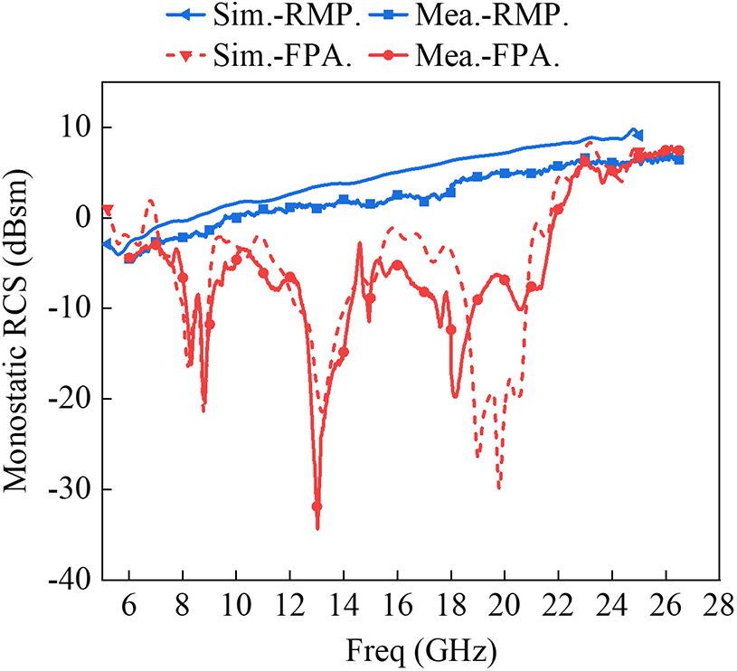
The simulated and measured RCS results are presented in Fig. 20. The measured RCS reduction bandwidth of the proposed FPA is 102.3% (7.3–22.6 GHz), which agrees well with the simulated result of 104% (7.2–22.8 GHz). The maximum RCS reduction reaches 35.3 dB at 13.03 GHz, indicating that both in-band and out-of-band RCS reductions are effectively achieved. The discrepancies between the measured and simulated results can be attributed to fabrication tolerances and measurement uncertainties.
monostatic RCS. RMP.: Reference metal plate. FPA.: proposed FPA.

Compared with the related works listed in Table 3, the proposed antenna demonstrates superior performance in terms of gain and RCS reduction bandwidth, except for the designs reported in [Reference Gao, Yan, Jie and Hua19] and [Reference Yao, Gao, Tian, Wu, Guo and Huang21]. Although the maximum RCS reduction in [Reference Zheng, Gao, Zhou and Cao24] reaches as high as 39.4 dB, its RCS reduction bandwidth is only 76.92%. While the impedance bandwidth and RCS reduction bandwidth in [Reference Gao, Yan, Jie and Hua19] are both broader than those of the proposed design, its maximum gain is limited to 11.9 dBi. Although [Reference Huang and Fan18] demonstrates superior impedance and gain bandwidths compared to the proposed design, its peak gain and RCS reduction bandwidth are limited to 15.5 dBi and 83.7%, respectively. Compared to Ref. [Reference Liu, Liu, Borenmann and Zhao37], the proposed antenna achieves not only a broader high-gain bandwidth but also an optimized electromagnetic field distribution, a feature not emphasized in the design in [Reference Liu, Liu, Borenmann and Zhao37]. The five different-sized FSS unit cells in this work realize a gradient reflection magnitude R and positive slope phase, not only enhancing broadband high gain but also optimizing aperture illumination and improving the antenna’s electric field distribution. Furthermore, the proposed antenna achieves similar gain and RCS performance at a smaller size. In conclusion, the proposed FPA achieves both ultra-wideband RCS reduction and high gain, exhibiting excellent overall performance and making it an outstanding candidate for stealth communication applications.
Performance Comparison with Previous Works

Note: that, AMC: Artificial Magnetic Conductor; PCM: Polarization Conversion Metasurface; RCS: Radar Cross Section; BW.RCS: RCS reduction bandwidth; M.RCS.: Maximum RCS reduction; –: Data not provided.
Conclusion
This paper presents an FPA with stable gain and low RCS, achieved using a novel hybrid metasurface. Theoretical analysis and experimental results jointly confirm that the introduction of a phase gradient and a reflection coefficient that gradually decreases from the center to the periphery, facilitated by a hybrid metasurface with positive reflection characteristics, significantly broadens the impedance bandwidth, enhances radiation gain, and effectively reduces RCS. The proposed antenna demonstrates a measured –10 dB impedance bandwidth of 22.47%, a peak gain of 17.25 dBi at 7.2 GHz, and a 3-dB gain bandwidth of 18.2%. Furthermore, an extensive RCS reduction bandwidth from 7.3 to 22.6 GHz is achieved, with a maximum reduction of 35.3 dB observed at 13.03 GHz. These results suggest that the proposed antenna is a strong candidate for integration into stealth communication systems and other advanced electromagnetic applications.
Acknowledgements
This work was supported by the Key Research and Development Program of Guangdong province under Grant 2024B0101020006, and the State Key Laboratory of Metamaterial Electromagnetic Modulation Technology Open Fund (Research on low RCS reconfigurable antenna based on electromagnetic metamaterials).
Competing interests
The authors declare none.

Wenjian Wang received the M.S. degree in Environmental Chemistry from Fuzhou University, Fuzhou, Fujian, China, in 2010. Since then, he has joined the Kuang-Chi Institute of Advanced Technology, China, where he was a researcher in electronic engineering. He is currently pursuing the Ph.D. degree in the College of Electronics and Communication Engineering, Sun Yat-Sen University, Shenzhen, China. His current research interests include metamaterials, high-gain antenna arrays, radar, RCS reduction, ultrawideband technology, and wave propagation in complex media.

Lihui Wang received the M.S. degree in communication and information systems from Yunnan University, Kunming, China, in 2022, and he is currently pursuing the Ph.D. degree at the School of Electronics and Communication Engineering, Sun Yat-Sen University, Shenzhen, China. His current research interests include phased array antenna technology and millimeter-wave antennas for satellite communications.

Qiuhua Lin received the B.S. degree from Hubei University of Arts and Science in 2018 and the M.E. degree from Yunnan University, Kunming, China, in 2022. He is currently pursuing the Ph.D. degree at Sun Yat-sen University, Shenzhen, China. His current research interests include communication, electronic information, and other related professional fields, including theoretical and design research.

Da Hou received the B.S. degree from the Changsha University of Science and Technology, Changsha, China, in 2020, and the M.S. degree in communications and information systems from Yunnan University, Kunming, China, in 2023. He is currently a joint Ph.D. student at Sun Yat-sen University and Pengcheng Laboratory. His current research interests include computational electromagnetics, microwave sensors, frequency-selective surfaces, and filtering antennas.

Songtao Yang is a senior engineer at Kuang-Chi Institute of Advanced Technology, China. His research interests include electromagnetic wave testing.

Pengpeng Chen received the B.S. degree in Measurement and Control Technology and Instrument from Wuhan University in 2021. He is currently pursuing the master’s degree at the School of Electronics and Communication Engineering, Sun Yat-sen University. His current research focuses on wideband circularly polarized metamaterial antennas.

Zhiyong Luo received the Ph.D. degree from the University of Electronic Science and Technology, Chengdu, China, in 2000. He is currently a professor at the School of Electronics and Communication Engineering, Sun Yat-Sen University, Shenzhen, China. He has participated in national key defense projects such as 995/810/934. His research interests include communication, electronic information, and networks.