

DISCUSSION POINTS
-
• Currently, automatic implantable cardiac defibrillators (AICDs) last roughly for 8 years, whereas the average patient lifespan is more than 20 years. This gap requires the patient to undergo battery replacement surgery, resulting in additional discomfort and costs. Development of bioenergy harvesters that supplement existing battery life can help bridge this gap.
-
• Further, additional power supply could power sensors on implantable devices, which could provide clinically important information to the surgeons. Availability of critical information can facilitate rapid decision making and shorter outpatient times.
Introduction
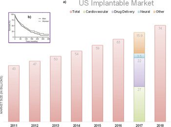
The US implants is a $54.3B (2014) industry and is expected to grow at a fast rate of 8% compounded annually. Cardiovascular implants comprise a majority (40%) of all the devices implanted and the remaining 60% of the powered implants market is fragmented into drug delivery, neural, and other small categories. It is estimated that cardiovascular implants itself will be a $27B industry by 2017 [Fig. 1(a)]. Drug delivery devices come at a close second market, with a compounded growth rate of 4% and forecasted to exceed $22B by 2017 [Fig. 1(a)]. 3
(a) Current and predicted US Implantable Market size (in billions). Estimated market forecast for 2017 showing the distribution among the various implant categories. Data source: Ref. Reference Bruce1; (b) Kaplan–Meier survival analysis of patients with atrial fibrillation, post pacemaker implantation showing a sharp decline in the survival rate as the time increases. Source: Ref. Reference Asbach, Olschewski, Faber, Zehender, Bode and Brunner2. Reproduced with permission. Copyright 2008, Oxford University Press.

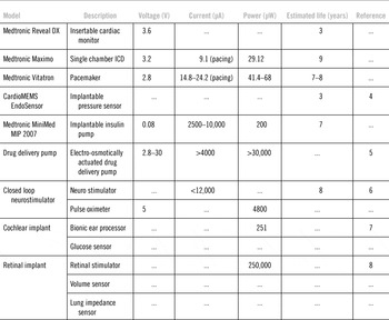
The advent of lithium-based batteries spurred the growth of powered implantable devices. Two of the most frequently implanted cardiovascular devices, the automatic implantable cardiac defibrillator (AICD) and pacemaker, still rely on lithium-ion batteries as their sole power source. Table 1 summarizes some of the powered implantable devices along with their power requirements and estimated lifetime.
Comparison of present day implantable devices along with their power requirements.

It is estimated that the average life of an internally implanted battery-powered AICD is less than half of the normal lifespan of a patient after having an AICD implanted [Table 1, Fig. 1(b)]. While the longevity of the average AICD patient has increased to 10 years post implantation, Reference Asbach, Olschewski, Faber, Zehender, Bode and Brunner2 only a few implants function for seven years, Reference Sanders, Hlatky and Owens9 and this mismatch poses a significant and ever growing clinical and economic burden. Approximately 90% of AICDs and biventricular pacemakers implanted in 2004 required replacement. Reference Sanders, Hlatky and Owens9 The rate of replacement of pacemakers and AICDs is dependent on the battery capacity and the degree of pacing or occurrence of defibrillation.
Therefore, if the battery is implanted, it must someday be replaced and the battery's limited capacity accounts for more than 55% malfunctions in conventional pacemaker and AICDs. Reference Maisel10 Every time a surgery is performed, there is an inherent risk and discomfort to the patient.
Moreover, there are now efforts to “piggyback” sensors on all implantable devices for additional functionality such as pressure and volume sensors to warn of impending congestive heart failure (CHF), lung impedance sensors to warn of CHF, and chemical sensors to provide telemetric measures of glucose, potassium, bun and creatinine, all of which would require additional power. Reference Huegl, Bruns, Unterberg-Buchwald, Grosse, Stegemann, Lauer and Gasparini11–Reference Kassab, Svendsen, Combs, Choy, Berbari and Navia15
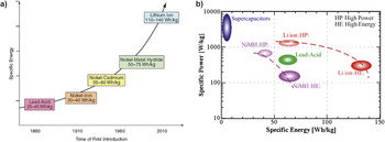
More than four decades ago, alternative sources of energy were considered to be a hot research topic for implants due to the short lifespan of the mercury-based batteries. Reference Kreysa, Sell and Kramer16–Reference Mele, Cardos and Videla18 The power output of these first implantable fuel cells in the 1970s was in the range of 50 µW, sufficient to supply a present day-cardiac pacemaker. Reference Weidlich, Richter, Sturm and Rao19 Introduction of lithium-based batteries in the 1970s Reference Präuer, Wirtzfeld, Lampadius, Himmler and Werber20 put all research on alternative energy sources to a grinding halt. While the introduction of lithium-based batteries provided significant step in device lifetime, advancements in battery life have started to slow down [Fig. 2(a)]. Therefore, the research focus has shifted toward the development of compact, efficient, and low-power consuming implants. With the emergence of micro-electro mechanical systems (MEMSs), fabrication of low-power devices can now be realized. Reference Laser and Santiago21–Reference Najafi and Ludomirsky31 But for even very low-power consuming devices, the use of batteries is not considered to be a viable long-term solution. Batteries are bulky for MEMS-based implants and for larger implants such as pacemakers, defibrillators, and cardiac monitors, batteries provide limited lifespan.
(a) Rapid advancements in increasing power density trend for batteries since the first lead-acid batteries were introduced in the mid-19th century Reference Roberts42 ; and (b) specific power versus specific energy of modern storage devices: supercapacitor, lead-acid, NiMH, and Li-ion battery technology. Reference Thounthong, Chunkag, Sethakul, Davat and Hinaje43

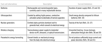
As biomedical industry seeks to create smarter, intelligent, and more sophisticated implantable devices, increases in battery energy capacity have become a limiting factor rather than a supporting one. Alternative technologies of charging such devices in a continuous and stable manner have become an issue of great importance. Availability of additional energy will not only allow the existing powered implantable devices to carry additional sensors for smarter diagnosis, but also it can help realization of new, smart implants. Table 2 lists the possible alternative technologies along with an understanding of their current limitations.
Summary of possible fuel-cell technology alternatives and their current limitations.
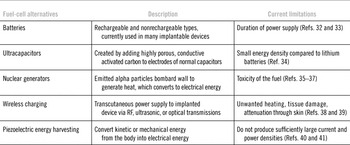
This study is dedicated to presenting a brief overview of these possible energy generating mechanisms with a focus on one of the most promising avenues of energy generation: abiotic glucose fuel cells (AGFCs).
Batteries and alternative energy sources for implants
Presently, all of the implantable devices rely on electric energy supplied by batteries. The demand of durability between charge cycles can only be satisfied with new power supply concepts. Batteries with limited capacities will eventually drain long before the service life of the system. Their continuous replacement is a growing burden that adds to outgoing patient costs and concerns. The energy density (energy per unit of volume) and the specific energy (energy per unit weight) of several primary batteries (nonrechargeable) and secondary batteries (rechargeable), which are candidates for power portable devices, are compared in Fig. 2(b). But the trend toward lower power consumption stimulates the investigation for alternative power sources to traditional batteries.
For implantable biomedical devices, internal batteries and ultracapacitors have the disadvantage of duration of power supply because it is often limited by the capacity of the battery, i.e., it is limited by the quantity of the available reactants in the system. Reference Lanmüller, Bijak, Mayr, Rafolt, Sauermann and Thoma32 The energy generated by the battery is based on electrochemical reactions. Once the potential and current levels in the device have reduced, the battery is unusable and replacement of batteries becomes necessary. Replacing batteries Reference Shill33 in implantable systems can pose a significant issue. Surgical interventions would be the only option to replace the batteries that have failed or that reach the end of its lifetime of operation. These operations could have detrimental effects such as scarring, infection or they could prove to be really expensive.
The increase in power density in batteries trend has started to stagnate. The need for high power densities has led to the development of ultracapacitors. Ultracapacitors are generally created through adding a highly porous, conductive activated carbon to the electrodes of normal capacitors. The additional surface area allows for higher energy densities of up to 100x of traditional capacitors. Reference Chandrakasan, Verma and Daly44 Generally, ultracapacitors have only a fraction (∼5%) of the energy densities of lithium batteries, but research is attempting novel solutions that could provide comparable results. Reference Signorelli34
Alternate sources to batteries that could be implanted into biomedical devices were nuclear generator. This idea was conceived in 1960 and brought to the clinical environment in 1970. Numec Corporation developed this prototype where alpha particles emitted by a tiny slug of plutonium 238 bombarded with the walls of its container producing heat that was converted to electrical energy. Reference Parsonnet and Manhardt35–Reference Laurens37 Although safety was not the primary issue there were concerns about the toxicity of the fuel.
A number of biomedical-based implantable medical devices would benefit from miniaturized MEMS-based implantable power supplies. One of the most important applications are cardiac pacemakers that currently use lithium-ion batteries that power these devices with an operating power of 1 µW. Reference Holmes45,Reference Linden and Reddy46 These batteries have an energy density of 1 W/mL. Biofuel cells created thus far have energy density of 10 mW/mL but this value could be improved to that of conventional lithium-ion batteries. The advantages of biofuel systems are that it can provide constant energy density that is derived from ambient sugars present in the body.
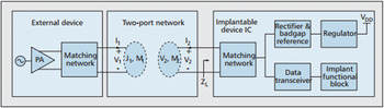
Wireless charging of medical implants is an exciting field that has the ability to not require an implanted power source. Radiofrequency, Reference Schuder47–Reference Smith, Tang, Johnson, Pourmehdi, Gazdik, Buckett and Peckham49 ultrasound, Reference Suzuki, Katane and Saito50 and optical Reference Goto, Nakagawa, Nakamura and Kaata51 methods have been studied as possible methods for delivering power transcutaneously to implanted medical devices or act as rechargeable batteries. This energy transmission does not require wire leads that penetrate the skin. RF transmissions have shown high efficiency but have also been prone to unwanted heating and tissue damage. Most battery-less implantable devices have the following components Reference Yakovlev, Kim and Poon52 :
-
(i) Matching network – used to maximize power delivery efficiency through antenna pairs
-
(ii) Rectifier – conversion of AC to DC voltage
-
(iii) Regulator – stabilize supply voltage to circuitry
-
(iv) Bandgap reference – stable reference voltage for the regulator
Together, these components create the basis for a system that can gather RF power from an external device and provide stable enough supply voltage/current for usage of the implanted device (Fig. 3). Reference Yakovlev, Kim and Poon52
Block diagram showing the various components of a wireless transmission system utilizing RF antennas for energy transfer. Key components include the matching network, rectifier, regulator, and band gap reference. Source: Ref. Reference Yakovlev, Kim and Poon52.

An alternative method of wireless charging is through focused ultrasound or optical waves to transmit energy. Ultrasound and optical methods have the disadvantage of becoming attenuate through the skin. Optical methods using infrared means is sometimes associated with unwanted heating of the skin. Reference Tang, Tummala, Gupta and Schwiebert53 Typical setups include a focused transmitting transducer, a receiving transducer, a DC converter (rectifier), and a recharging battery (secondary battery). Reference Yakovlev, Kim and Poon52 The receiving transducer is typically a piezoelectric transducer that converts the mechanical energy into electrical energy. This method has the ability to supplement secondary battery progress to provide a feasible, long-term solution for power generation for medical implants without requiring battery replacement.
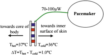
Another mechanism of generating power in implantable devices is thermoelectric modules. Thermoelectric modules use temperature differences between the core body and inner skin surface to generate electric energy. This gradient can be around 0.3–1.5 °C and is enough to generate 70 μW or higher. Reference Watkins, Shen and Venkatasubramanian54 This technology at its current stage would not be able to support an implanted device, but could be used to supplement battery power to increase battery lifetime (Fig. 4).
Schematic of a thermoelectric module showing the module attached to a pacemaker as an energy supplement to extend the lifetime of the pacemaker battery. The diagram demonstrates the approximate temperature difference available in the body. Source: Ref. Reference Watkins, Shen and Venkatasubramanian54.

Piezoelectric power sources convert kinetic or mechanical energy into electrical energy. These systems do not produce sufficiently large current and power densities for implantable medical device applications. Reference Goto, Sugiura, Harada and Kazui55,Reference Kaster, Lillehei and Starek56 Recently, researchers Reference Wang and Song57 have developed a prototype in the nanometer scale that produces continuous direct current by harvesting energy from the environment such as ultrasound, vibrations, and blood flow. These devices are made of vertically aligned zinc oxide nanowires that generate electricity when they are bent. This piezoelectric device is attractive toward biomedical applications because zinc oxide is nontoxic and biocompatible.
However, ZnO wires are inflexible and brittle (modulus of 21 GPa and fracture strain of several percent Reference Desai and Haque58 ). Additional wires in the device could not solve the problem, as fracture of a few would lead to catastrophic failure of other wires since the total mechanical load would be distributed among fewer wires. This fact could compromise the efficacy of implanted AICD with power generation capabilities.
Piezoelectric polymers, such as poly(vinylidene difluoride) (PVDF), have significant advantages over ZnO and other ceramics. PVDF's mechanical properties are better representative of current AICD lead materials (fracture strain of many tens of percent Reference Fang, Zhang and Yang59 and modulus an order of magnitude lower than ZnO), indicating that PVDF devices will be more robust, with less impact on lead mechanical properties. PVDF also makes an ideal biomaterial because it is nontoxic, inert, resistant to water absorption (absorbs <0.04% w), biocompatible, Reference Nalwa60 and clean-room friendly. In contrast, ZnO is difficult to pattern, assemble into devices, stack in multiple layers, and encapsulate. Reference Agren61–Reference Olsen65
Several groups have worked on developing piezoelectric energy harvesting for implantable devices. Reference Ramsay and Clark66 Some groups have worked with PZT 5A, PZT 5H, and PVDF membranes to produce power from fluctuating blood pressure. Although most of these devices produced power, the power was insufficient to run the device for the proposed application.
The most successful power recovery schemes from body motion using PVDF devices were able to convert ∼1% of mechanical energy into electrical energy. Reference Fourie67 Assuming similar efficiencies for PVDF devices implanted into AICD leads, it could be possible to generate 10–50 mW (1–5 W mechanical power from heart Reference Avraham68 ), which is higher than the ∼5 mW used by typical pacemakers with 4–5 years of battery lifetime. While PVDF devices have not been utilized for heart applications, they have been incorporated to harvest energy from respiration as early as the 1980s. It was determined that 1 mW of electrical power could be generated from respiration processes (∼1 W total mechanical energy). Reference Hausler and Stein69–Reference Starner71 While few advances have been made beyond these initial demonstrations, the understanding of piezoelectricity of bulk PVDF was just emerging in 1984 (Ref. Reference Lovinger72) and has since developed substantially. Recent work utilizing PVDF nanofibers Reference Chang, Chang, Tran, Wang, Fuh and Lin73 and the enhancement of the properties of crystallizing polymers using 10–100 nm layers provides future opportunities in this area.
Implantable fuel cells
Basic principle
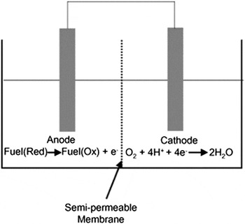
In a chemical fuel cell, electrical energy is generated by the electrochemical reaction of fuel and oxidant at two spatially separate electrodes. Reference Kreysa, Sell and Kramer16 Electrons, released upon the electro-oxidation of the fuel, flow from the anode through an external load circuit to the cathode, where the terminal electron acceptor, usually oxygen, is reduced (Fig. 5). A number of groups, such as Aston et al., Reference Turner, Aston, Higgins, Davis and Hill74 Benneto, Reference Akiba, Bennetto, Stirling and Tanaka75 Katz, Reference Katz, Buckmann and Willner76,Reference Katz and Willner77 Barton and Atanasso, Reference Barton and Atanassov78 etc. have worked on bioelectrochemistry that use compounds such as sugars found in vivo. Glucose, being the most abundant molecule, is also the most commonly targeted preferred fuel for an implantable fuel cell. The driving force of the electron flow is the difference in electrochemical potential of electrolyte near the anode and the cathode.
Schematic of a basic biofuel cell consisting an anode, cathode, and a semipermeable membrane. Reference Davis and Higson79

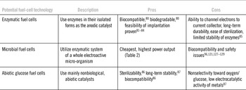
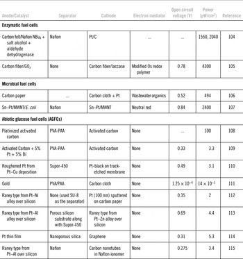
In general, glucose-consuming fuel cells can be divided into three main types according to the type of catalyst that is used to enable the electrode reactions: enzymatic, microbial, and AGFCs. Table 3 provides an overview of the various types of biofuel cells along with their advantages and disadvantages while Table 4 gives a few examples of the common types of biofuel cells and their characteristics.
Potential fuel-cell technologies along with their pros and cons for powering implantable devices.

Comparison for various cells.

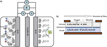
Enzymatic fuel cells use enzymes such as glucose oxidase and laccase in their isolated forms as the anodic catalyst. Figure 6(a) demonstrates the layout of their enzymatic cell. An extensive review of enzymatic fuel cells has been reported previously by a number of research groups. Palmore and Whitesides Reference Palmore, Bertschy, Bergens and Whitesides88,Reference Palmore and Kim89 have summarized the concepts, device designs, and performance of biofuel cells. Katz and Willner Reference Willner63,Reference Katz, Buckmann and Willner76,Reference Katz and Willner77,Reference Katz, Filanovsky and Willner90–Reference Willner, Yan, Willner and Tel-Vered98 have discussed the progress of novel electrode designs and chemistries for enzymatic fuel cells. Heller Reference Heller99–Reference Heller101 reviewed the advances in miniaturized biological fuel cells. Such fuel cells can potentially run in living systems, taking the oxygen and the fuel required for operation from the environment. Since the enzymes are coated on a flat electrode surface, channeling of electrons from the catalysis site to the current collector remains a huge issue. Hence, suitable electron mediators are used that can shuttle between the site of catalysis and the current collector facilitating the transfer of electrons. However, most of the suitable electron mediators are toxic in nature, making them unsuitable for implantable application. Heller came up with the concept of wired enzymes that enable rapid transfer of electrons from enzyme domains to the current collector. Reference Heller99 They can be used for a wide variety of implantable medical devices. Recent developments have created a fully biocompatible and biodegradable enzymatic biofuel cells utilizing single-walled carbon nanotubes bioconjugated with glucose oxidase and with a catalase anode. In this cell, Stolarczyk et al. were able to create a power density of 60 µW/cm2 with the ability to increase power output further through aligning multiple fuel cells in series. Reference Stolarczyk, Kizling, Majdecka, Zelechowska, Biernat, Rogalski and Bilewicz80 Further innovations in the field of enzymatic biofuel cells include the nanofabrication of electrodes using carbon nanotubes, allowing for tight packing of electrodes. This has allowed a much higher power density to be achieved (18 mW/cm2) than is typically seen in enzymatic cell. Reference Kanwal, Wang, Ying, Cohen, Lakshmanan, Patlolla, Iqbal, Thomas and Farrow102 Further, many trials have shown the feasibility of implanting enzymatic biofuel cells into hosts ranging from rats to snails. Reference Miyake, Haneda, Nagai, Yatagawa, Onami, Yoshino, Abe and Nishizawa81–Reference Szczupak, Halámek, Halamkova, Bocharova, Alfonta and Katz84 However, it is unlikely that these trials will lead to their implementation in human hosts anytime in the near future due to multiple unaddressed issues, Reference Magnus Falk, Babanova, Atanassov and Shleev85 including the long-term durability, ease of sterilization, and limited stability of enzymes.
(a) Schematic of enzymatic biofuel cell demonstrated by Stolarczyk et al. showing mechanism of oxidation at the biological – gold-coated electrode (GCE) anode and reduction at the cathode Reference Stolarczyk, Kizling, Majdecka, Zelechowska, Biernat, Rogalski and Bilewicz80 ; and (b) schematic of AGFC showing mechanism of selective glucose oxidation by oxygen depletion at the cathode. Source: Ref. Reference Sharma103.

In microbial fuel cells, the enzymatic system of a whole electroactive micro-organism is used. The use of microorganisms in biological fuel cells eliminates the isolation of individual enzymes. Hence, microbial fuel cells are the cheapest among all biological fuel cells. There has been exciting progress on the energy obtained from microbial fuel cells based on the different microbes, Reference Ishii, Watanabe, Yabuki, Logan and Sekiguchi116–Reference Wang, Tsujimura, Cheng and Kano123 electrode materials, Reference Birry, Mehta, Jaouen, Dodelet, Guiot and Tartakovsky124–Reference Mohan, Raghavulu and Sarma129 electron mediators, Reference Sharma, Reddy, Chandra and Ramaprabhu107,Reference Barrière, Ferry, Rochefort and Leech130–Reference Sharma, Reddy, Chandra and Ramaprabhu133 bioreactors, Reference Ishii, Watanabe, Yabuki, Logan and Sekiguchi116,Reference Wang, Bernarda, Huang, Lee and Chang134–Reference Hu137 and substrates. Reference Pant, Van Bogaert, Diels and Vanbroekhoven138 Even though microbial fuel cells provide the highest power output among the different types of fuel cells (Table 2), power-supply systems based on microbial fuel cells are not seriously considered for implantation due to concerns of safety and biocompatibility of implanting bacteria. Reference Sharma, Reddy, Chandra and Ramaprabhu107,Reference Sharma, Reddy, Chandra and Ramaprabhu133,Reference Fernández, Mano, Heller and Bard139–Reference Minteer, Liaw and Cooney141
Abiotic glucose fuel cells (AGFCs)
Abiotically catalyzed fuel cells use mainly nonbiological, abiotic catalysts (noble metals or activated carbon) and are therefore considered to be advantageous regarding their sterilizability, long-term stability, and biocompatibility. Reference Rao and Milazzo86
The power output of these initial AGFCs was in the range of 40 µW, Reference Weidlich, Richter, Sturm and Rao19 when implanted outside the abdomen cavity of dogs, sufficient to run a present-day ICD independent of a battery (Table 1). The duration of early AGFCs in animal trials amounted to more than 150 days Reference Weidlich, Richter, Sturm and Rao19 of continuous energy production. AGFCs provide superior advantages over conventional batteries by eliminating patient costs associated with battery replacements, and allowing newer devices which require energy to be piggybacked onto AICDs and biventricular pacemakers. Among the fresh research carried out on implantable AGFCs, the body of work done by Kerzenmacher and Stetten Reference Kerzenmacher, Ducrée, Zengerle and Von Stetten109,Reference Kloke, Kerzenmacher, Zengerle and von Stetten110,Reference Kerzenmacher, Kräling, Metz, Zengerle and Von Stetten113,Reference Kerzenmacher, Ducrée, Zengerle and Von Stetten142–Reference von Stetten, Kerzenmacher, Lorenz, Chokkalingam, Miyakawa, Zengerle and Ducree149 is the most extensive and in-depth.
Theoretically, glucose can be completely oxidized to carbon dioxide and water, releasing 24 electrons per molecule glucose. Reference Kerzenmacher, Ducrée, Zengerle and Von Stetten142 To simulate the physiological environment for testing the implantable AGFC, glucose solution in phosphate-buffered saline (PBS; pH = 7.4) is most commonly used. However, the transfer of 24 electrons per molecule glucose has not yet been achieved. Rao and Drake reported gluconic acid to be the only reaction product that could be identified by thin layer chromatography. Reference Rao and Milazzo86 The oxidation of glucose to gluconic acid only yields two electrons per molecule of glucose and the corresponding electrode reactions are given by:
 $${\rm{Anode}}:\;{{\rm{C}}_6}{{\rm{H}}_{12}}{{\rm{O}}_6} + 2{\rm{O}}{{\rm{H}}^ - } \to {{\rm{C}}_6}{{\rm{H}}_{12}}{{\rm{O}}_7} + {{\rm{H}}_2}{\rm{O}} + 2{{\rm{e}}^ - },$$
 $${\rm{Cathode}}:\;0.5{{\rm{O}}_2} + {{\rm{H}}_2}{\rm{O}} + 2{{\rm{e}}^ - } \to 2{\rm{O}}{{\rm{H}}^ - },$$
 $${\rm{Overall}}\;{\rm{reaction}}:\;{{\rm{C}}_6}{{\rm{H}}_{12}}{{\rm{O}}_6} + 0.5{{\rm{O}}_2} \to {{\rm{C}}_6}{{\rm{H}}_{12}}{{\rm{O}}_7},$$
 $$\Delta G^\circ = - 2.51\; \times \;10^5 \;{{\rm{J}} \mathord{\left/ {\vphantom {{\rm{J}} {{\rm{mol}}}}} \right. \kern-\nulldelimiterspace} {{\rm{mol}}}};\;V^\circ = 1.30\;{\rm{V}}.$$
where ΔG° is the change in standard Gibbs free energy and V° is the standard reaction potential. This correlates to a maximum coulombic efficiency of 8%. Reference Palmore, Bertschy, Bergens and Whitesides88,Reference Rapoport, Kedzierski and Sarpeshkar115
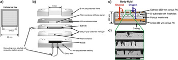
In practice, the theoretical voltage is never achieved due to the lack of a metal catalyst that can selectively oxidize glucose from blood. The presence of oxygen (along with other amino acids) in blood interferes with glucose oxidation at the anode. Hence, there has been significant effort to develop better anodic catalysts for AGFCs. Commonly used sandwiched-electrode design [Figs. 6(b) and 7(a)–7(c)] helps circumvent this problem to a certain extent by consuming oxygen at the oxygen-selective cathode (usually carbon based), leaving glucose for oxidation at the anode. Reference Kerzenmacher, Ducrée, Zengerle and Von Stetten109 Various AGFC designs have been described in detail previously by various authors and summarized by Kerzemacher et al. Reference Kerzenmacher, Ducrée, Zengerle and Von Stetten142,Reference Kerzenmacher, Mutschler, Kräling, Baumer, Ducrée, Zengerle and von Stetten148
Abiotic glucose fuel cell construction details. (a) Top view of a permeable cathode, (b) cross-sectional view of the binder-less glucose fuel cell assembly. (c) Schematic of binder-less cathode, and a self-supporting platinum anode-based glucose fuel cell. Source: Ref. Reference Kerzenmacher, Kräling, Metz, Zengerle and Von Stetten113; and (d) cross-sectional views of (a) Pt–Al60, (b) Pt–Al120, and (c) Pt–Al240 Raney-platinum cathodes fabricated for oxygen depletion. Source: Ref. Reference Kerzenmacher, Kräling, Schroeder, Brämer, Zengerle and von Stetten147. Copyrights permission 2014 Elsevier.

Cathode
Conventionally, platinum is the most favorable material of choice for oxygen reduction. Historically, platinum was kept restricted to the anode material due to the ability of platinum to adsorb and oxidize glucose under low oxygen conditions. As the fabricated cathodes were thick (several hundred micrometers in thickness), simultaneous reduction of oxygen and oxidation of glucose on the same cathode material would drastically lower AGFC power output.
Hence, most of the studies reported the use of activated carbon as the cathode material Reference Kerzenmacher, Ducrée, Zengerle and Von Stetten109,Reference Kerzenmacher, Ducrée, Zengerle and Von Stetten142,Reference Kerzenmacher, Ducree, Zengerle and von Stetten145,Reference von Stetten, Kerzenmacher, Lorenz, Chokkalingam, Miyakawa, Zengerle and Ducree149 (Table 4). Activated carbon does not show any affinity toward glucose and exhibits a better oxygen reduction performance compared to silver. Reference Kerzenmacher, Ducrée, Zengerle and Von Stetten142 An inherent problem associated with the use of activated carbon is the bulk resistivity and the electrical connectivity of the powdered materials. Reference Kerzenmacher, Kräling, Metz, Zengerle and Von Stetten113 Carbon-based cathode materials are usually mixed with a binder such as polyvinyl alcohol – polyacrylic acid (PVA-PAA), polytetrafluoroethylene (PTFE), or Nafion as a support for the catalyst material. The binders add to the bulk resistivity of the cathodes, however.
It has been shown that the oxygen adsorption on activated carbon occurs on the graphene edges of activated carbon and the mechanism of oxygen reduction involves oxidation of such sites. Reference Oliveira, Silva, Yoshida and Lago150 Hence, activated carbon might not be a long-term solution for implantable biofuel cells. In other words, the mass of activated carbon to be used for building cathode materials in AGFCs needs to be estimated before long-term claims can be made. Kerzenmacher et al. Reference Kerzenmacher, Ducrée, Zengerle and Von Stetten109 demonstrated a glucose fuel cell running on activated carbon for 234 days, which could generate energy capable of powering an artificial pacemaker. However, they also showed that with time, appreciable oxygen crossover takes place from the cathode to the anode, leading to degradation in the cell performance. Moreover, the highly tortuous structure of activated carbon-based cathode also decreases diffusion to the anode.
By using a thin (<500 nm) film of porous Pt, Kerzenmacher et al. were able to avoid the generation of oxygen-depleted sites on the same electrode [Fig. 7(d)]. Reference Kerzenmacher, Kräling, Schroeder, Brämer, Zengerle and von Stetten147 This allowed fabrication of a platinum-based binderless cathode whose performance was comparable with that of activated carbon at 7% oxygen saturation (physiological conditions) Reference Kerzenmacher, Kräling, Ducrée, Zengerle and von Stetten151 [Fig. 7(c)].
Membrane
Separator membranes provide electrical insulation between the electrodes while at the same time they serve as a diffusion barrier to certain chemicals. Given the electrolytic character of body fluids, it would be sufficient to apply a mesh-like hydrophilic spacer as separator membrane, its pores filled with body fluid.
However, the ionic nature of the separator and the corresponding capability to transport either OH− or H+ ions influences the electrode reactions. In the case of AGFCs using an oxygen-selective cathode catalyst the separator must not only be an ionic conductor but also allow for the diffusion of fuel and its reaction products to and from the anode.
For conventional membrane use, a variety of materials are reported to be suitable, among them weak cation exchange hydrogels of the poly(vinyl alcohol)-poly(acrylic acid) type, glycolmethacrylate, cuprophane, sufonated PTFE membranes. Reference Rao, Richter, Von Sturm and Weidlich17,Reference Weidlich, Richter, Sturm and Rao19,Reference Kerzenmacher, Ducrée, Zengerle and Von Stetten109 Difficulties were encountered with hydrogels based on poly(vinyl alcohol)-poly(acrylic acid) (PVA-PAA) and glycolmethacrylate, that were disconnected after prolonged fuel cell operation, presumably due to hydrolysis or the oxidative effect of electrocatalysts. Reference Kerzenmacher, Kräling, Metz, Zengerle and Von Stetten113 Nafion is another popular membrane among all due to its excellent proton conducting properties. Extensive research on Nafion membrane due to hydrogen fuel cell research makes it an easy favorite. Reference Rapoport, Kedzierski and Sarpeshkar115 A common challenge with polymer membranes is the nonisotropic polymerization, which leads to high variation in the localized physical properties of the membrane. Further, the thickness of the membranes is typically on the order of a few hundred micrometers, increasing the overall AGFC thickness and presenting a significant diffusion barrier for glucose. Moreover, polymer membranes are prone to swell and delaminate, and have been a nidus for infection when implanted in vivo. Reference Weidlich, Richter, Sturm and Rao19,Reference Rao and Richter152 An advantage of using Nafion is that it can be easily spin coated and patterned using photoresist. Reference Rapoport, Kedzierski and Sarpeshkar115 Fabrication of uniform films and patterning of the membrane, with high precision, will be of great importance moving forward if mass production of AGFCs is to be realized.
In recent studies, the use of patternable inorganic membranes has been realized. In particular, Sharma et al. Reference Sharma, Hu, Stoller, Feldman, Ruoff, Ferrari and Zhang114 used 300 nm thin mesoporous (nanoporous) silica films as the separator membranes. Since mesoporous silica films are obtained from spin-coated films of organosilicates, it can also be used to fabricate conformal coatings for uneven surfaces. Kerzenmacher et al. Reference Kerzenmacher, Kräling, Metz, Zengerle and Von Stetten113,Reference Kerzenmacher, Kräling, Schroeder, Brämer, Zengerle and von Stetten147 used silicon substrate with patterned feedholes as the membrane. Both the fuel cell setups showed promising power output and performance (Table 4). In general, inorganic membranes do not swell, can be fabricated into thin films, offer good opportunity for custom surface chemistries over organic membranes. Clearly, the use of inorganic membranes demonstrates the critical role of a membrane in maximizing the AGFC efficiency.
AGFCs without membrane have also been created, leading to lower ohmic resistance and better glucose diffusion. Reference Oncescu and Erickson112 Separation of glucose and oxygen was achieved instead through using a stacked electrode design, where layer of patterned SU-8 was used as the spacer. The peak power output of the cell was approximately 2 µWcm−2 with a sustainable output of 1.5 µWcm−2 at 10 µAcm−2. This design of membrane-less AGFCs is sustainable as long as a gap is maintained between the cathode and anode, preventing them from shorting.
Anode
Noble metal catalysts are well known for oxidation of carbohydrates. Reference Rao, Richter, Von Sturm and Weidlich17,Reference Rao and Milazzo86,Reference Rao, Richter, Von and Weidlich108,Reference Rao and Richter152 Gold-based electrodes have been popular for oxidation of glucose under alkaline conditions. However, it tends to have extreme instability and low oxygen tolerance, Reference Ivanov, Vidaković and Sundmacher153 making it inappropriate as anode for implantable application. Alternative metals act as better catalysts for AGFCs. But they fail to deliver under the physiological conditions. Reference Ghaffari, Asgarpour, Mousavi and Salehieh111 Since pure platinum undergoes irreversible oxidation and poisoning easily, roughened platinum has exhibited better, stable performance. In attempts to develop thin and highly active glucose anodes which permit generation of the required energy in the smallest possible volume, Raney noble metal catalysts supported on a metal foil followed by dissolution of the metal catalyst was adopted. Reference Kloke, Kerzenmacher, Zengerle and von Stetten110,Reference Kerzenmacher, Ducrée, Zengerle and Von Stetten142 Rao et al. Reference Rao, Richter, Von Sturm and Weidlich17,Reference Weidlich, Richter, Sturm and Rao19,Reference Rao, Richter, Luft and von Sturm154 showed using this method that they could dissolve 79% of the nickel content starting from an initial Pt–Ni (1:6) alloy, resulting in 50–60 µm deep cracks perpendicular to the surface while still being active and shear resistance. While this set of experiments were done about four decades ago, Kloke et al. Reference Kloke, Kerzenmacher, Zengerle and von Stetten110 were able to recreate an AGFC with 3.1 µW/cm2 using a similar technique. They were able to create a highly porous platinum anode through alternation of electrodeposition of a platinum–copper alloy followed by electrochemical extraction of the copper. To fabricate a permeable cathode, the group deposited platinum black on a gold-coated polycarbonate track-etch membrane (PC-TEM).
More recently, Kerzenmacher et al. revived the Raney type metal catalyst anodes by dissolving zinc and aluminum from platinum alloys to improve the biocompatibility of the fuel cell. Reference Kerzenmacher, Ducree, Zengerle and von Stetten145 The Raney type anode was also tested in the presence of various amino acids, resembling physiological fluid. Zinc or nickel leakages during fuel cell operation were found to be negligible, making it suitable for implantable devices. This new structure showed a significant improvement in mechanical and chemical stability while still showing comparable glucose oxidation performance. The complete fuel cells showed a maximum power density of up to 4.4 µW/cm2 with open circuit potential of 0.7 V at 7% oxygen saturation. Reference Kerzenmacher, Kräling, Metz, Zengerle and Von Stetten113
Fuel cell assemblies
Nonselectivity toward oxygen or glucose and the low electrocatalytic activity of metals are still problems slowing the use of AGFCs. However, their long-term stability makes them attractive for future development in implantable devices. Reference Cosnier, Le Goff and Holzinger87 Several significant milestones have been achieved in the field of AGFCs within the last decade itself. Demonstration of the Raney type platinum-based electrodes as both the anode and cathode eliminated the necessity to rely on bulky, resistive hydrogel binder-based cathodes for oxygen reduction. Studies have used 500 nm thin films of porous platinum as the cathode material to demonstrate the feasibility. The thickness of cathode is critical in maximizing the cell potential; also affected by or dependent on the diffusion properties across the various membrane barriers used by the assembled AGFC. Greater than required thickness can lead to glucose and oxygen redox reaction taking place on the same electrode. Thinner than required electrodes would lead to oxygen diffusion to the anode, thereby causing the same redox reaction on the anode. The thickness of the cathode in such a case can be further optimized using advanced computational models, to balance between oxygen crossover and glucose oxidation at the porous platinum-based cathodes. Such computational models would also need to account for the complex diffusion across the membrane.
Computational models can also give insight into better design for membranes and implantation sites as well. Implant sites determine the concentrations of free dissolved oxygen, glucose, and other fibrinogenic factors. Earlier studies have considered implanting in body cavities due to the bulkiness of AGFCs. Such cells could be incorporated as an external coating of the implantable devices and would harness energy from the ambient glucose and oxygen supplied to the body tissue. Redesigning the biofuel cell for vascular implant, on the other hand, would require development of ultrathin AGFCs. The recent increase in neural and cerebral implants have led to development of ABFCs for cerebrospinal implantation as well. Reference Rapoport, Kedzierski and Sarpeshkar115 The cerebrospinal fluid is virtually acellular, is under minimal immune surveillance, has a 100-fold lower protein content than blood and other tissues and is therefore less prone to induce biofouling of implanted devices, and its glucose levels are comparable to those of blood and other tissues. Rapoport et al. were the one of the first to develop and test AGFCs specifically for implant in the brain. Reference Rapoport, Kedzierski and Sarpeshkar115 They also used Raney type platinum film patterned on silicon wafer as the anode (Table 4).
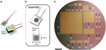
While using Raney type platinum films as electrodes hold great potential for future cell designs, commercialization of AGFCs would need development of patterned electrodes and membrane for consistent, predictable performance. Recent studies have started to integrate electrodes using silicon as the main substrate Reference Oncescu and Erickson112,Reference Rapoport, Kedzierski and Sarpeshkar115,Reference Kerzenmacher, Kräling, Ducrée, Zengerle and von Stetten151,Reference Oncescu and Erickson155 (Fig. 8). This also allows patterning of the required CMOS circuitry on the same substrate. Rectifier-based energy harvesting circuits Reference Chen, Sharma, Chen, Fu and Zhang156 can be used to tap the maximum energy from the system. Further, development of flexible AGFCs would facilitate its use as a conformal coating on the surface of the powered implantable device.
Photographs showing various AGFCs using custom silicon patterned electrodes for low-power implantable devices. Sources: Refs. Reference Oncescu and Erickson155, Reference Oncescu and Erickson112, and Reference Rapoport, Kedzierski and Sarpeshkar115.

Summary
While there are many potential sources of power, fuel-cell technologies have shown great potential for implantable applications and are the focus of research over the past few decades. Biofuel cells have the advantage over existing technologies, such as lithium-iodine batteries, in implantable devices such as heart pacemakers. Ideally, an implanted biofuel cell would use metabolite fuel such as glucose or lactate, both of which are readily available in the human body. Clearly, implantable fuel cell has come a long way since the 1960s. And the vast scope of opportunities opens up lot of gray areas as well. Rapid progress in this field requires interdisciplinary efforts in instrumentation, material sciences, microfabrication, and biomedical engineering. Biofuel cells hold great promise moving forward for cardiovascular and neural powered implants.
Acknowledgments
This research was supported by National Science Foundation grants (ECCS 1128677, ECCS 1309686). We gratefully acknowledge the partial financial support from the Thayer School of Engineering at Dartmouth.