I. INTRODUCTION
The antenna arrays are now the milestone for modern communication systems. They play a major role in the design of smart antenna arrays. The antenna arrays can be steered electronically toward the desired destination without the involvement of any mechanical parts using smart antenna algorithms [Reference Deng1, Reference Jabbar2]. This feature makes the arrays an intriguing choice for many wireless system designers. The arrays are serving in many civil [Reference Roberts3–Reference Oliveri, Rocca and Massa6] and military systems now [Reference Lu7]. Despite many attractive properties that the arrays have, they also suffer from many drawbacks. The uniform arrays are very susceptible for element loss because their tuning frequency depends on the distance that separates its elements. Besides, the uniform arrays are designed based on a single frequency that defines its whole structure. This makes it unsuitable for the systems that implement multi-carriers for their links. To overcome these limitations, new approaches were suggested to rebuild the arrays such as the random array and the fractal array [Reference Jabbar8–Reference Elhefnawy and Ismail10]. In [Reference Jabbar8], the author gave a comparison study for these different array geometries. Also, he suggested new fractal array geometries that have a superior response compared with the uniform or random and even the well-known Sierpinski fractal array. He also pointed out that the limitations of the fractal arrays such as tuning frequency are rigidly related to fractal nature and thus the array is tuned to certain frequency bands. The other obstacle is the number of elements per array which is governed by the level of iterations and the fractal generator.
Researchers around the world are investigating the possibility of building the optimum array. This array should have no side-lobe levels (SLLs). There are many approaches to achieve an optimized array. The ways to improve array response might concentrate on increasing the directivity (thinning the beam width angle) or decreasing the SLL or pushing the SLLs away from the main-lobe (ML) [Reference Singh and Jha11]. The response of the non-uniform planar antenna array (NUPAA) can be significantly improved using optimization algorithms to find phase shifters weights for the array that can enhance the performance. Many approaches were put to test to achieve this goal. These approaches are either statistical approaches [Reference Chatterjee and Mahanti12–Reference Wang, Jiao and Tan16], evolutionary [Reference Li17–Reference Golubovi and Olcan22], or modified algorithms [Reference Li23–Reference Mehrabian34]. The physical locations of the elements are left intact. This means that the tuning frequencies are not altered. In this research, we have chosen the maximization of the ML to SLL because of its dramatic impact on array performance. The reason behind that is when we decrease the SLL we are actually decreasing the leaked power from the ML to the SLLs which consequently leads to a decrease in the interference level. This will eventually increase the signal-to-interference and noise-ratio (SINR) which improves the communication quality and immunity to noise or interference. In other words, the required power for transmission will be decreased. To carry out the optimization, invasive weed optimization (IWO) is chosen because it adopts a novel technique in its approach. This technique gives this algorithm an impressive performance compared with the known evolutionary algorithms such as the particle swarm optimization (PSO) or the genetic algorithm (GA). The new technique in IWO is very simple and yet it is powerful. It simply does not rollout the individuals that have fitness less than the preset. The algorithm keeps them alive until the total number of elements exceeds the defined population. This gives the algorithm a thorough investigation capability for all the possible solutions to come up with the most optimized configuration [Reference Mehrabian34].
II. THEORY AND ANALYSIS
This section will be devoted to a discussion of the theoretical aspects of this work.
A) The array factor (AF) and its relation to elements physical locations
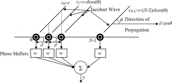
The array is conceptually comprised of multiple radiating elements (antennas) that are placed in a confined area. These elements interact with each other producing what is called the array factor. Assume for simplicity the uniform linear array shown in Fig. 1 which has an incident wave at an angle θ and N isotropic elements to investigate the AF because each of these elements has a unity radiation pattern. If another type of antenna is used then the radiation will be the multiplication of AF by the new antenna radiation pattern [Reference Jabbar8].
Simple linear antenna array.

All elements are separated by a distance d. The wave travels at a rate of kd cosθ, where k is the propagation factor k = 2π / λ and λ is the tuning frequency.
If we assume that the nth element has a phase-dependent electric current density I n, then the total far electric field, using the superposition theorem [Reference Mailloux35], is
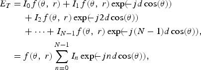 $$\eqalign{E_T=\,& I_0 f\lpar \theta\comma \; r\rpar +I_1 f\lpar \theta\comma \; r \rpar \exp \lpar \!\!- jd\cos \lpar \theta \rpar \rpar \cr & +I_2 f\lpar \theta\comma \; r \rpar \exp\lpar \!\!- j2d\cos \lpar \theta \rpar \rpar \cr & +\cdots+I_{N - 1} f\lpar \theta\comma \; r \rpar \exp \lpar \!\!- j\lpar N - 1 \rpar d\cos \lpar \theta \rpar \rpar \comma \; \cr =\,& f\lpar \theta\comma \; r \rpar \sum\limits_{n=0}^{N - 1} I_n \exp \lpar \!\!- jnd\cos \lpar \theta \rpar \rpar \comma \; } $$
where f(θ, r) is the element radiation pattern in spherical coordinates.
We can see from equation (1) that the array pattern is the multiplication between the elements radiation pattern and another term which is the AF.
For the isotropic element f(θ, r) = 1 which leaves only the AF. Hence, the AF is [Reference Gross36, Reference Blaunstein and Christodoulou37 and Reference Jaggard and Jaggard38]
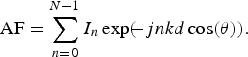 $${\rm AF}=\sum\limits_{n=0}^{N - 1} I_n \exp \lpar \!\!- jnkd\cos \lpar \theta \rpar \rpar .$$
The output of the summer y is (assuming the incident signal = 1, zero noise for simplicity)
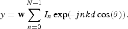 $$y={\bf w}\sum\limits_{n=0}^{N - 1} I_n \exp \lpar \!\!- jnkd\cos \lpar \theta \rpar \rpar .$$
To neutralize the effect of AF we must use the relation given by equation (4)
 $${\bf w} \cdot {\bf AF}=1 \Rightarrow {\bf w}^H={\bf AF}\comma \; $$
where H is the Hermitian operator (transpose conjugate).
The values of w vary with θ and they do not vary with d because d is constant here.
We can extend the above analysis for the two-dimensional array [Reference Kritikos and Jaggard39–Reference Mehrabian and Lucas41]
 $${\rm AF}=\sum\limits_{n=0}^N I_n \exp \lpar \!\!- j2\pi \lpar k_x x_n+k_y y_n \rpar \rpar \comma \; $$
where x is the position of the element along the x-axis, y is the position of the element along the y-axis
 $$k_x=k\sin \theta \cos \varphi\comma \; \quad k_y=k\sin \theta \sin \varphi .$$
By substituting equation (5) into equation (3), we have
 $$y={\bf w}^H \sum\limits_{n=0}^N I_n \exp \lpar \!\!- j2\pi \lpar k_x x_n+k_y y_n \rpar \rpar . $$
To illustrate how we can use the weighing vector w to optimize the array response, consider equation (3) and by taking its z-transform we obtain
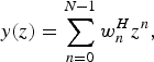 $$y\lpar z\rpar =\sum\limits_{n=0}^{N - 1} w_n^H z^n \comma \; $$
where
 $$z=\exp\lpar \!\!- jdk\cos \lpar \theta \rpar \rpar .$$
Since a polynomial can be written as the product of its own zeros, it follows that
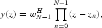 $$y\lpar z\rpar =w_{N - 1}^H \prod\limits_{n=0}^{N - 1} \lpar z - z_n \rpar \comma \; $$
where z n are the zeros of y. By selecting the required zeros and setting equation (8) to equation (6), the weights can be derived. This is equivalent to the z-transformation of the Finite Impulse Response (FIR) filters. By using the filter coefficient to optimize its response, we can also use w to optimize the array response [see Appendix]. The weighting vector is called here the aperture function. Hence, we can use w to ensure that the response of the array is optimum in relation to the SLL or the AF directivity.
B) The IWO and the PSO optimization algorithms
1) Invasive weed optimization
IWO is suggested by Mehrabian and Lucas [Reference Mehrabian and Lucas41]. It is based on the strategy of weeds for survival. The weeds have been around for billions of years. Inspite of the harsh weather or the cruel environment, the weeds managed to survive. The weeds spread their seeds randomly and these seeds travel with animals or air or with water to new areas. The human starts to taste the agony of eradicating these weeds since he started to plant his first plant. The weeds kept invading his farms and competing with the crops on the available resources. Humans tried to eliminate them by rooting them out, burning them with fire, and recently using chemical and biological agents to eliminate these weeds. In every confrontation with the humans, the victory is always for the weeds because of their survival strategy that was developed since the beginning of life. The strategy is very simple and potent. It simply depends on the surrounding environment which is either hostile or habitable.
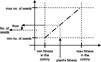
If the environment is hostile then the plants follow the “Live short, mature fast, seed a lot and die young” strategy. When the environment is friendly, then the plants follow “Live long, mature slow, seed a little, and die old” strategy to eliminate the possibility of resources competition. As we can see, the plants with fitness less than that required for survival are granted the right to live and spore which means we do not need to eliminate them because they might be the lead to the solution. This new aspect which appears for the first time in this algorithm is the corner stone of the power of this algorithm. The seeding procedure is shown in Fig. 2 [Reference Mehrabian34].
The seeding procedure of the IWO.

The hostile environment is equivalent for being away from the solution. At that area, the plants flourish fast, seed many, and die quickly in their quest to discover a welcoming area (optimized solution). Once a solution is found, the plants will last longer than the others, seed little, and die old which means this will drag distant plants to a near spot than to a welcoming location. During the dragging process, the migrating plants comb the area for what might be a better solution. If it is found, the process of migration will be switched to the newly discovered spot, and so on.
The seeding equation is given by equation (9) [Reference Ahmed and Ruhul Amin42]
 $$\sigma _{iter}=\displaystyle{\lpar iter_{\max } - iter \rpar ^m \over \lpar iter_{\max }\rpar ^m}\lpar \sigma _{initial} - \sigma _{final}\rpar +\sigma _{final}\comma \; $$
where σ is the standard deviation of the seeds dispersal random function, m is the nonlinear modulation index, and iter is the number of iterations
By altering the value of m, we can control the location of the seeds for the next generation. The process continues while the population is less than the maximum giving the chance for infeasible plants to grow. When the population exceeds the maximum, the less fitting plants are discarded. This process continues until we reach a solution.
2) Particle swarm optimization
PSO was originally created by Kennedy et al. [Reference Mehrabian and Lucas41] during their observation of wild life communities [Reference Kennedy and Eberhart43]. Thereafter, they discovered the optimization capability of this algorithm. The PSO is based on the observation of how the bird flocks or fish schools or any similar communities behave during their mass migration from one area to another. These particles tend to organize themselves in tight formation to follow the leader which has the best fitness. Every particle should maintain a distance from its neighbor particle to avoid collision, unlike the IWO that allows the particles to coincide on the same spot. Each particle is a candidate for a solution. Once one of the particles discovers a solution, the rest of the particles follow it. During the process the other particles are sweeping the area for better solutions to take the lead. To formulate the algorithm, first start by generating the particle population randomly using a uniform probability density and then consider equation (10) that represents the velocity of each particle [Reference Tanji, Matsushita and Sekiya44]
 $$\eqalign {v_{ij} \lpar \delta+1\rpar & =\eta v_{ij} \lpar \delta \rpar +\gamma _1 U\lpar 0\comma \; 1\rpar \lpar p_{ij} \lpar \delta \rpar - x_{ij} \lpar \delta \rpar \rpar \cr & \quad +\gamma _2 U\lpar 0\comma \; 1\rpar \lpar p_{gj} \lpar \delta \rpar - x_{ij} \lpar \delta \rpar \rpar \comma \; }$$
where i, j are the particle indexes on the x–y coordinates, v ij is the velocity of the i, jth particle, δ is the iteration index, η is an inertia weight, x is the position of the particle, p ij is the best position found by the i, jth particle, p gi is the best position found by the swarm (global position), U(0,1) is the uniformly distributed random variable in the range from 0 to 1, and γ 1 and γ 2 are the acceleration coefficients that permit movement of the swarm considering the social or the cognitive term, respectively.
The position x is updated using equation (11)
 $$x_i \lpar \delta+1\rpar =x_i \lpar \delta \rpar +v_i \lpar \delta+1\rpar .$$
The value of the acceleration terms specifies the tension and the distance between the particles. If the value is set to a high value then the swarm will collapse quickly toward global fitness. Although, if the value is set to a low value then the particles will have enough time to thoroughly investigate the local solutions, but at the expense of time consumption. Hence, setting these values requires careful adjustment. The inertia controls the impact of previous velocities with the current one. The higher the inertia the more favored the global exploration, whereas low inertia favors local exploration. The straying particles (low fitness) can cause a decrease in fitness. The biggest swarm will attract the scattered particles. When ample particle concentration is reached (fitness level) the optimization process is stopped.
C) The chaos game algorithm
This algorithm was originally coined by the English mathematician Michael Barnsley [Reference Barnsley45]. He suggested the algorithm as a very simple method to generate a fractal. It is based on the theory of random walk where an event occurs randomly. The decision for the current step is based on the last result (Markov process). Each output of the random process is mapped with a scale between a vertex of a pre-defined geometric shape and the last point.
Assume an affine map that defines a fractal
 $$W=\left\{f_1\comma \; \ldots\comma \; f_n \right\}\comma \; $$
where  $\forall f_i \in \lcub \Re ^2 \rcub $ and
 $\Re ^2$ represent the real numbers group and
 $$f_i \lpar \lsqb x\comma \; y\comma \; 1\rsqb \rpar =\lsqb x\comma \; y\comma \; 1 \rsqb F_i\comma \; $$
where F i is a fractal generator matrix.
For every mapping f i we define a probability p i > 0 such that 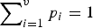 $\sum\nolimits_{i=1}^v {p_i }=1$ where v is all of the possible processes. Now, we draw mapping f i with probability p i, where i ∈ {1,…,v} and we transform the point with this mapping. This new point is initial point (IP) for the next step which is exactly the same as the first step. Hence, we draw mapping and transform the point with this mapping. The new point is the IP for the next step. We repeat the procedure again and again.
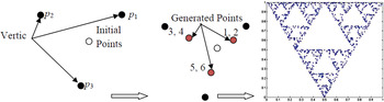
For example, define three vertices and a random point, IP, as shown in Fig. 3. We can use a dice, or any process that produces a random output to map the next point between the IP and a vertex. Let us assume that if the output is 1 or 2 then the point resides between IP and p 1, if the output is 3 or 4 then we choose IP and p 2 and if the output is 5 or 6 we choose p 3. The next point will be considered as the new IP and the next toss will define the location between the new IP and one of the vertices. After many trials we will obtain a Sierpinski triangle. The output of the game can be changed by changing the location of the IP; even if we use the same set of random variable values. In addition, we can change the fractal shape by changing the number of the vertices and their locations (equation 13).
The CGA output (Sierpinski triangle).

III. SIMULATION RESULTS
In this study, we adopt the same fractal configuration given by Jabbar [Reference Jabbar8]. The author showed that these fractal arrays have a superior performance in comparison with the uniform or random planar arrays or the famous Sierpinski fractal antenna array. Nevertheless, the author also pointed out that there are two obstacles that might restrict the implementation of such arrays. The first is the number of elements in any fractal which is not optional because it is constrained by the nature of the fractal generator and the fractal iteration level. The fractal is a self-similar entity that replicates itself indefinitely. Hence, the number of elements is a multiplicative number of the original shape. This means that if we need to design an array with a certain number of elements we might end up with either much less or much more than the required number.
The second obstacle is related to the tuning frequency. The AF of the fractal antenna array is [Reference Jabbar8, Reference Werneer, Haupt and Werner46–Reference Azaro48]
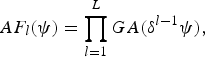 $$AF_l \lpar \psi \rpar =\prod\limits_{l=1}^L GA\lpar \delta ^{l - 1} \psi \rpar \comma \; $$
where l represents the iteration level, GA represents the generating AF,  $\psi=kd\sin \left({\theta\comma \; \vartheta } \right)$, θ and ϑ are the azimuth and elevation angles, respectively, and δ is the excitation phase scale for each element.
This means that the tuning frequencies are dictated by the fractal shape and the iterations level.
To investigate the multi-tuning frequency property of the chaos game algorithm (CGA) array (CGAA), consider Fig. 3 in which the elements of the array are generated. To ensure that there is no grating in the AF of the antenna array, the spacing between two adjacent elements should be λ/2 [Reference Van Trees49]. The instantaneous distance after the trial i is
 $$d_{i+1}=\left\vert IP_i - \Delta _j \cdot \lpar IP_i - p_j \rpar \right\vert \comma \; $$
where IP i is the initial point for the ith trial, Δj is the scaling factor that corresponds to the jth vertex, and p j is the jth vertex of the polygon.
The relation between the wavelength of inter-element spacing is λ i = 2d i and the frequency is f i = c/λ i+1, where c is the light velocity in free space, the instantaneous frequency is
 $$f_i=\displaystyle{c \over 2d_{i+1} }.$$
Equation (16) shows that the resultant array has multi-tuning frequencies depending on the outcome of the Markov process.
We suggest using the CGA to generate fractal geometry without the ordinary fractal array restrictions. The first limitation, which is the number of elements, can be solved in CGA because we can generate any number of elements using the required trials during the game. For this reason, each simulated array will have 1000 elements [Reference Hall50–Reference de Lera-Acedo52] which are hardly to be synthesized using an ordinary fractal array.
The tuning frequencies, as shown in equation (16), are determined by the spacing between two adjacent elements. The CGA can produce random tuning frequencies because the spacing is specified by a random process. If we need other frequencies or a better tuning level we can simply either change the IP location or use a different set of random processes and keep the same fractal shape.
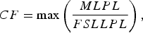
The other contribution is to optimize the response of the generated array by maximizing the ML to the SLL which is shown by the cost function in equation (17). IWO is used for that purpose and the results are compared with a proven optimization algorithm which is the PSO. The first SLL was chosen for the optimization process because of its high contribution in the degradation of the SINR and the complexity to suppress these lobes due to their adjacency to the ML.
 $$CF=\max \left({\displaystyle{{MLPL} \over {FSLLPL}}} \right)\comma \; $$
where MLP is the main-lobe peak level and FSLLPL is the first-side lobe-level peak level.
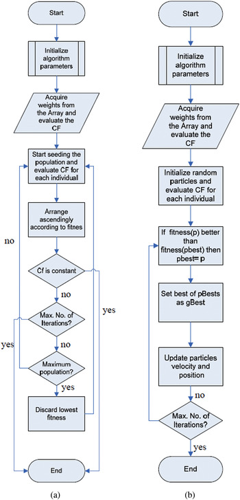
The MLP can be found from equation (5) which represents the value of 1. The FSLLPL is the first local maxima next to the ML. After finding these values, we can apply them to equation (17) so as to be used by the optimization algorithm. The flow charts for the two algorithms are shown in Fig. 4. The settings for each algorithm are
PSO: iterations = 10, inertia = 1, acceleration = 2, and swarm population = 100.
IWO: no. of initial plants = 10, max plants = 100, max iterations = 10, seed max = 10, seed min = 2, non-linear modulation index = 3, initial standard deviation = 1, and final standard deviation = 10−16.
The flowchart of (a) IWO and (b) PSO.

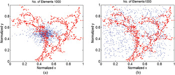
In the beginning, for both of the algorithms, the positions of the generated arrays represented the starting point which they used to disperse their particles or seeds. Thereafter, the algorithm will swap the original location with the newly generated position if their fitness is higher. When the termination condition is met, the algorithm will take the first 1000 points with highest fitness to be as the final solution to the optimization problem.
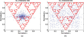
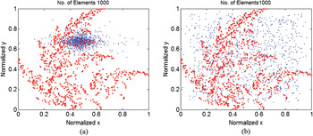
The first array is the Sierpinski triangle which is shown in Fig. 5. The physical locations of the elements are represented by the red dots, whereas the optimized weights are superimposed on the same array using the blue dots.
Sierpinski CGAA with optimized weights: (a) PSO output and (b) IWO output.

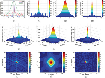
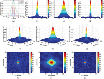
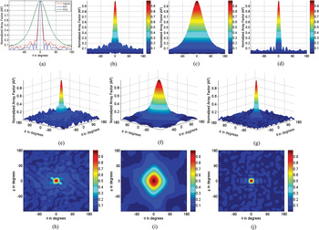
The optimized AF using PSO and IWO of the above array is shown in Fig. 6 in Cartesian coordinates and top view
The AF of Sierpinski CGAA in Cartesian coordinates: (a) 2D AF, (b) colored original AF, (c) PSO optimized colored AF, (d) IWO optimized colored AF, (e) 3D Cartesian of the original AF, (f) 3D Cartesian of the PSO optimized AF, (g) 3D Cartesian of the IWO optimized AF, (h) top view of the original AF, (i) top view of the PSO optimized AF, and (j) top view of the IWO optimized AF.

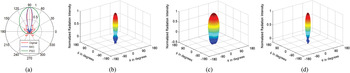
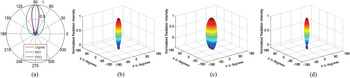
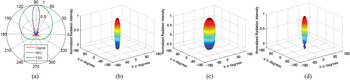
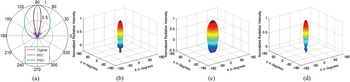
The polar plot of the AF is shown in Fig. 7.
The AF of Sierpinski CGAA in polar coordinates: (a) polar AF, (b) 3D polar of the original AF, (c) 3D polar of the PSO optimized AF, and (d) 3D polar of the IWO optimized AF.

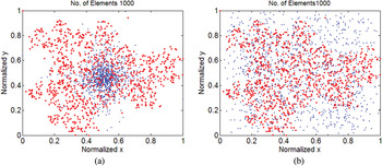
The Dragon fractal that has the best AF regarding the SLL is shown in Fig. 8.
Dragon CGAA with optimized weights: (a) PSO output and (b) IWO output.

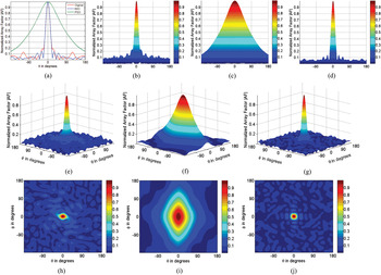
The optimization failed to find better weights than the original to minimize the SLLs however the directivity is increased in the IWO algorithm. The results in Cartesian coordinates are shown in Fig. 9.
The AF of Dragon CGAA in Cartesian coordinates: (a) 2D AF, (b) colored original AF, (c) PSO optimized colored AF, (d) IWO optimized colored AF, (e) 3D Cartesian of the original AF, (f) 3D Cartesian of the PSO optimized AF, (g) 3D Cartesian of the IWO optimized AF, (h) top view of the original AF, (i) top view of the PSO optimized AF, and (j) top view of the IWO optimized AF.

The polar AF is shown in Fig. 10.
The AF of Dragon CGAA in polar coordinates: (a) polar AF, (b) 3D polar of the original AF, (c) 3D polar of the PSO optimized AF, and (d) 3D polar of the IWO optimized AF.

The twig CGAA optimized array weights are shown in Fig. 11.
Twig CGAA with optimized weights: (a) PSO output and (b) IWO output.

The optimization results of the IWO and PSO algorithms for the twig array are shown in Figs 12 and 13 in Cartesian and polar form
The AF of Twig CGAA in Cartesian coordinates: (a) 2D AF, (b) colored original AF, (c) PSO optimized colored AF, (d) IWO optimized colored AF, (e) 3D Cartesian of the original AF, (f) 3D Cartesian of the PSO optimized AF, (g) 3D Cartesian of the IWO optimized AF, (h) top view of the original AF, (i) Top view of the PSO optimized AF, and (j) top view of the IWO optimized AF.

The AF of Twig CGAA in polar coordinates: (a) polar AF, (b) 3D polar of the original AF, (c) 3D polar of the PSO optimized AF, and (d) 3D polar of the IWO optimized AF.

The last array is the flap array which is shown in Fig. 14.
Flap CGAA with optimized weights: (a) PSO output and (b) IWO output.

The results of the IWO and PSO algorithms are shown in Figs 15 and 16 in Cartesian and polar coordinates.
The AF of Flap CGAA in Cartesian coordinates: (a) 2D AF, (b) colored original AF, (c) PSO optimized colored AF, (d) IWO optimized colored AF, (e) 3D Cartesian of the original AF, (f) 3D Cartesian of the PSO optimized AF, (g) 3D Cartesian of the IWO optimized AF, (h) top view of the original AF, (i) top view of the PSO optimized AF, and (j) top view of the IWO optimized AF.

The AF of Flap CGA array in polar coordinates: (a) polar AF, (b) 3D polar of the original AF, (c) 3D polar of the PSO optimized AF, and (d) 3D polar of the IWO optimized AF.

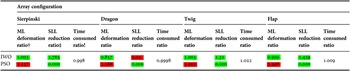
Table 1 summarizes the simulation results for the above antennas for the PSO and IWO, whereas Table 2 gives a numerical comparison for both of the algorithms performance for 20 runs.
Antenna arrays simulation results.

Numerical performance comparison of the algorithms.

†ML deformation = optimized ML/original ML.
‡SLL reduction = original SLL/optimized SLL.
!Time consumed ratio = IWO time/PSO time.
Good.
Bad.
IV. CONCLUSION
From the above analysis and results we can conclude that the CGAAs are very powerful replacements for the fractal arrays of the same shape. The required number of elements is not restrained by the generator nature as for the fractals. In addition, the arrays generated by the CGA have the geometrical properties of the fractal especially area compactness. Also, they have multi-tuning frequencies which are not related to the generator like the fractals.
The PSO showed unwanted results compared with the IWO for all of the arrays under investigation. The PSO succeeded in finding an optimum array without SLLs at the expense of ML complete deformation. Actually, these results are not accepted because the ML should sustain its shape to a tolerable extent. The final results of the PSO show a high concentration (swarming particles) that led to the deterioration in performance. On the other hand, the IWO gave very realistic results. In all the array configurations, the IWO succeeded in finding a set of weights that minimize the SLL and keep the ML almost the same. The only exception is the Dragon array where the SLL is increased along with the directivity. The interesting point here is that during the elimination process the original weights are dropped due to their low fitness and replaced with new generated ones. These new weights might not lead to a lower SLL. Nevertheless, we cannot go back and retrieve the original weights because the optimization system is not a memory system. That is why the IWO could not keep the original Dragon shape and replaced it with the new calculated weights.
ACKNOWLEDGEMENT
The authors would like to express their sincere gratitude and appreciation to Dr Mehrabian, Ali R. for providing us with the general IWO Mat Lab code that helped us in the completion of this work.
Appendix
Consider the FIR filter, shown in the Fig. A.1
FIR filter

The output for the filter is
 $$y\lsqb n\rsqb = b_0 x\left[n \right]+ b_1 x\left[{n - 1} \right]+\cdots+b_N x\left[{n - \left({N - 1} \right)} \right]= \sum\limits_{i=0}^{i=N - 1} {b_i x\left[{n - i} \right]} $$
where:
x[n]: is the input signal
y[n]: is the output signal
N: is the filter order
b i: is the filter coefficients, or called tap weights.
If we set the input signal x[n] to δ[n], where δ is the Kronecker delta, then
 $$h\left[n \right]= \sum\limits_{i=0}^{N - 1} {b_i \delta \left[{n - i} \right]}=b_n \quad \hbox{for} \, n = 0 \, {\rm to} \, N-1 $$
By taking the Z-transform for h[n], we have
 $$H\left[z \right]= Z\left\{{h\left[n \right]} \right\}=\sum\limits_{n = - \infty }^\infty {h\lsqb n\rsqb z^{ - n} }=\sum\limits_{n=0}^{N - 1} {b_n z^{ - n} } $$
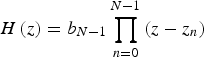
If we assume z = exp(− jω), then we can write the above equation in terms of its zero product as proposed by Schelkunoff
 $$H\left(z \right)= b_{N - 1} \prod\limits_{n=0}^{N - 1} {\left({z - z_n } \right)} $$
Consider the array factor given by Eq. 3. By setting z = exp(− jkd cos (θ)), we have
 $$y\left(z \right)= w_0 + w_1 z+\cdots+w_{N - 1} z^{N - 1} $$
Equation A.5 can also be written in terms of its zeros (Schelkunoff) as
 $$y\left(z \right)= w_{N - 1} \left({z - z_1 } \right)\cdot \left({z - z_2 } \right)\cdots \left({z - z_{N - 1} } \right)= w_{N - 1} \prod\limits_{n=0}^{N - 1} {\left({z - z_n } \right)} $$
By comparing Eq. (A.6) with Eqs. (A.4), we can see that b N−1 resembles w N−1H of the array factor.
 Ahmed N. Jabbar received the B. Sc. in 1994 and M. Sc. 1997 in the Electronic and Communication Engineering from Al-Nahrain University, Baghdad, Iraq. He worked as a head of computer science department in Al-Zintan Higher Institute for Trainers Preparation, Libya from 1998 to 2000. He worked as a teacher at Hadhramout University of Technology, Dept. of Electronic and Communication Eng. from 2002-2005. Currently he is teaching in the University of Babylon, Collage of Eng., Electric Dept. since 2005. His research interests include: the simulation and analysis of Antennas, Antenna Arrays, Smart Antenna Arrays, and Microwave devices.
 Ali Shaaban was born in Hilla city, Iraq, in 1981. He received the B. Sc. in 2003 from the University of Babylon and the M. Sc. in 2010 from University of Babylon, Hilla, Iraq. His main research interests are optimization techniques, microcontroller applications, and digital control. Currently he lectures at the University of Babylon.
 Muthana Khallil was born in Hilla city, Iraq, in 1982. He received the B. Sc. in 2003 from the University of Babylon and the M. Sc. degree from University of technology, Baghdad, Iraq. His main research interests are optimization techniques, DSP, and smart control. Currently he lectures at the University of Babylon.