
1. Introduction
The potential of biologically inspired flapping fin propulsion for practical applications lies in its predicted ability to provide high efficiency at a range of speeds, high manoeuvrability and a concealed profile. This has spurred a tremendous scientific effort over the last few decades (Triantafyllou, Triantafyllou & Yue Reference Triantafyllou, Triantafyllou and Yue2000; Smits Reference Smits2019) to understand and design bio-inspired propulsion techniques. A significant development within this design landscape is driven by recent developments in additive manufacturing and smart structures, so that robotic swimmers increasingly incorporate soft, flexible materials (Chu et al. Reference Chu, Lee, Song, Han, Lee, Kim, Kim, Park, Cho and Ahn2012; Christianson et al. Reference Christianson, Goldberg, Deheyn, Cai and Tolley2018; Katzschmann et al. Reference Katzschmann, DelPreto, MacCurdy and Rus2018). This leads to increasingly complex systems, whose behaviour is characterized both by passive elastic deformation of the structure as well as actuation degrees of freedom that can induce actively controlled shape changes. Consequently, there is a need to understand to what extent such dynamic shape changes affect hydrodynamic performance of flapping fin propulsion.
Passively deforming elastic surfaces have been studied extensively, as their input parameters and performance can be easily tested and controlled in experimental and numerical settings (Katz & Weihs Reference Katz and Weihs1978; Prempraneerach, Hover & Triantafyllou Reference Prempraneerach, Hover and Triantafyllou2003). Using two-dimensional (2-D) flat plates, Dewey et al. (Reference Dewey, Boschitsch, Moored, Stone and Smits2013) and Quinn, Lauder & Smits (Reference Quinn, Lauder and Smits2014, Reference Quinn, Lauder and Smits2015) show how the largest thrust is attained when a combination of heave and pitch of the leading edge is imposed so resonance with structural natural frequencies occurs. This conclusion is shared by Tytell et al. (Reference Tytell, Leftwich, Hsu, Griffith, Cohen, Smits, Hamlet and Fauci2016) using numerical simulations of a 2-D anguilliform swimmer modelled using a fully coupled biomechanical–hydrodynamic model. In three dimensions, Liu & Bose (Reference Liu and Bose1997) performed potential flow simulations of a heaving and pitching fin whale fluke, imposing spanwise deformations across the entire chord. Comparing with a rigid fin, they found spanwise deformations akin to elastic deformation to decrease efficiency and thrust, and spanwise deformations that mimic active deformations to increase thrust without affecting efficiency. Specifically for caudal fins, Zhu (Reference Zhu2007) and Zhu & Shoele (Reference Zhu and Shoele2008) performed potential flow coupled fluid–structure interaction simulations. They conclude that, for underwater swimming, increasing chordwise flexibility slightly increases efficiency and decreases thrust, whereas increasing spanwise flexibility decreases trust without significantly affecting efficiency.
The above works, except for Liu & Bose (Reference Liu and Bose1997), rely on a structural model of the fin to model passive, elastic deformations due to the hydrodynamic loading. Natural rayed fish fins, however, are composed of collagen membranes supported by bony rays that can be actively curved through a set of muscles at the base of each ray (Lauder & Drucker Reference Lauder and Drucker2004; Alben, Madden & Lauder Reference Alben, Madden and Lauder2007). As a result, dynamic curvature changes of real fish fins can consist of passive bending due to hydrodynamic loading, as well as active actuation of the individual rays against the flow (Fish & Lauder Reference Fish and Lauder2006). Biological observations show that this musculature is active even during steady swimming (Flammang & Lauder Reference Flammang and Lauder2008), and that these combined effects lead to complex three-dimensional (3-D) fin shapes (Bainbridge Reference Bainbridge1963; Lauder & Madden Reference Lauder and Madden2007; Lauder Reference Lauder2015) consisting of both chordwise (along rays) and spanwise (across rays) curvature components. This was quantified in Lauder et al. (Reference Lauder, Madden, Hunter, Tangorra, Davidson, Proctor, Mittal, Dong and Bozkurttas2005) and Bozkurttas et al. (Reference Bozkurttas, Tangorra, Lauder and Mittal2009), who used a proper orthogonal decomposition to break down the fin motion into various modes, observed also experimentally in real fish by Flammang & Lauder (Reference Flammang and Lauder2008, Reference Flammang and Lauder2009). Their results show how a discrete number of modes capture properly the most common fin motion gaits. Using a robotic rayed caudal fin model, Lauder et al. (Reference Lauder, Anderson, Tangorra and Madden2007), Tangorra, Esposito & Lauder (Reference Tangorra, Esposito and Lauder2009) and Esposito et al. (Reference Esposito, Tangorra, Flammang and Lauder2012) analysed the contribution to the thrust production for each of the individual deformation modes. They identified active cupping as the mode that produces the largest amount of thrust, where the spanwise shape variations are parabolic in nature, in phase with the pitch, and with the top and bottom rays leading the motion.
The above body of literature provides a picture that passive elastic deformations of flapping fins can improve their efficiency and thrust production, although finding the best structural design for a given hydrodynamic condition can be challenging. For spanwise elastic deformations the hydrodynamic trends and structural design criteria have not yet been systematically investigated. Further, there is an indication that actively curving fins against the hydrodynamic loading can improve hydrodynamic performance, but this requires further investigation.
Our current work is motivated by the wish to further understand the role of both passive and active curvature changes on the hydrodynamic performance of flapping fin propulsion. However, as opposed to the studies above, we do not explicitly consider any specific elastic model of the fin. Instead, we parametrize the dynamic chordwise and spanwise curvature variations of the fin geometry, and directly explore the effect of imposed curvature variations on hydrodynamic performance. This enables us to side step the fluid–structure interaction problem, and avoid making any assumptions about materials, elastic properties and actuation techniques. Instead, our approach aims to identify hydrodynamically beneficial curvature variations of the fin, and understand the underlying flow mechanisms. In a future step, this information can then be used as a target state for a fluid–structure interaction design study, aided by the capability of modern actuation mechanisms for shape-changing structures (Boley et al. Reference Boley, van Rees, Lissandrello, Horenstein, Truby, Kotikian, Lewis and Mahadevan2019).
In the following we detail the proposed mathematical representation of the fin geometry in § 2.1, showing its capability to reproduce typical swimming modes observed in nature. The 3-D Navier–Stokes solver used and its integration with the fin-shape generation algorithm is described next in § 2.2. The particular problem definition of a deforming fin subject to heave and pitch solid-body velocities, and the numerical set-up adopted to simulate it, are then explained in § 3. Simulation results from the parametric analysis of chordwise and spanwise curvature effects are presented in § 4, discussing in detail the impact of each curvature type in §§ 5.1 and 5.2. Finally, we present our concluding remarks in § 6.
2. Methodology
2.1. Description of fin shape
Our description and parametrization of the fin shape builds on our earlier work (Fernández-Gutiérrez & van Rees Reference Fernández-Gutiérrez and van Rees2020), with minor changes to the chordwise curvature coefficient definition and non-dimensionalization of the curvature description. For clarity and completeness we will therefore describe here the complete shape definition and its derivation.
2.1.1. Geometric model
We represent any fin geometry by a parametric 3-D mid-surface definition combined with a thickness distribution over it. Starting with the mid-surface, we introduce parameters  $(u,v)$ where
 $u \in [0,1]$ and
 $v \in [-1, 1]$. The undeformed mid-surface is defined as
 \begin{equation} \boldsymbol{r}_0(u, v) = \boldsymbol{r}_{LE}(v) + u \, c(v) \left[\cos(\beta(v)) \hat{\boldsymbol{x}} + \sin(\beta(v)) \hat{\boldsymbol{z}} \right], \end{equation}
where
 \begin{equation} \boldsymbol{r}_{LE}(v) = x_{LE}(v)\hat{\boldsymbol{x}} + v (H/2) \hat{\boldsymbol{z}} , \end{equation}
is the leading-edge (LE) position vector and  $x_{LE}(v)$ is the profile of the leading edge, as shown in figure 1. Further,
 $\beta (v)$ is the angle of the rays along the chordwise direction,
 $c(v)$ is the length of the chord as measured along a ray and
 $H$ the height of the fin at the leading edge (figure 1). The mapping and leading-edge position vector are defined such that, in
 $\mathbb {R}^{3}$, the
 $\hat {\boldsymbol {z}}$-axis corresponds to the axis of rotation of the fin. With the mid-surface defined, the description of the volumetric fin can be completed by the thickness function,
 $h(u,v)$, providing the distance between the outer fin surfaces along the normal of the fin's mid-surface. Throughout this work, we use the fin overall chord
 $C$ as length scale, defined as
 \begin{equation} C = \max_{u,v}(\boldsymbol{r}_0 \boldsymbol{\cdot} \hat{\boldsymbol{x}}) - \min_{u,v}(\boldsymbol{r}_0 \boldsymbol{\cdot} \hat{\boldsymbol{x}}) . \end{equation}
Notation and conventions for the geometric representation of the fin (a), and the local coordinate system (b).

To describe the deformed configuration of the mid-surface, we establish a Darboux frame along the rays, as shown in figure 1(b). The frame is characterized by the tangent unit vector along the rays,  $\hat {\boldsymbol {t}}$, the normal unit vector to the mid-surface,
 $\hat {\boldsymbol {n}}$, and the bi-normal unit vector
 $\hat {\boldsymbol {b}} = \hat {\boldsymbol {t}} \times \hat {\boldsymbol {n}}$. Note that our vectors
 $\hat {\boldsymbol {b}}$ and
 $\hat {\boldsymbol {n}}$ are rotated compared with the normal and binormal vectors arising using a Frenet framing of a space curve, due to the fact that, here,
 $\hat {\boldsymbol {n}}$ corresponds to the mid-surface normal vector. Using the Darboux framing, we can then define three non-dimensional curvatures corresponding to the directions of the local coordinate system, defined as
 \begin{equation} \left. \begin{array}{l@{}} \dfrac{\mathrm{d}\hat{\boldsymbol{t}}}{\mathrm{d}u} ={+} \kappa^{n} \hat{\boldsymbol{n}} + \kappa^{g} \hat{\boldsymbol{b}} \\ \dfrac{\mathrm{d} \hat{\boldsymbol{n}}}{\mathrm{d}u} ={-}\kappa^{n} \hat{\boldsymbol{t}} + \kappa^{t} \hat{\boldsymbol{b}} \\ \dfrac{\mathrm{d} \hat{\boldsymbol{b}}}{\mathrm{d}u} ={-}\kappa^{g} \hat{\boldsymbol{t}} - \kappa^{t} \hat{\boldsymbol{n}} \end{array} \right\} \quad\leftrightarrow \quad \left. \begin{array}{l@{}} \kappa^{t} = \dfrac{\mathrm{d}\hat{\boldsymbol{n}}}{\mathrm{d}u} \boldsymbol{\cdot} \hat{\boldsymbol{b}} ={-} \dfrac{\mathrm{d} \hat{\boldsymbol{b}}}{\mathrm{d}u} \boldsymbol{\cdot} \hat{\boldsymbol{n}} \\ \kappa^{g} = \dfrac{\mathrm{d}\hat{\boldsymbol{t}}}{\mathrm{d}u} \boldsymbol{\cdot} \hat{\boldsymbol{b}} ={-} \dfrac{\mathrm{d} \hat{\boldsymbol{b}}}{\mathrm{d}u} \boldsymbol{\cdot} \hat{\boldsymbol{t}} \\ \kappa^{n} = \dfrac{\mathrm{d}\hat{\boldsymbol{t}}}{\mathrm{d}u} \boldsymbol{\cdot} \hat{\boldsymbol{n}} ={-} \dfrac{\mathrm{d} \hat{\boldsymbol{n}}}{\mathrm{d}u} \boldsymbol{\cdot} \hat{\boldsymbol{t}} \end{array} \right\} , \end{equation}
where the curvatures are non-dimensional; the dimensionalized forms can be found when multiplying with the local chord  $c(v)$. More precisely, the values of
 $\kappa ^{t}$,
 $\kappa ^{g}$ and
 $\kappa ^{n}$, respectively, correspond to the geodesic torsion, geodesic curvature and normal curvature of the constant-
 $v$ curve on the mid-surface.
For the deformed configuration, we can then write the position of the mid-surface as
 \begin{equation} \boldsymbol{r}(u, v) = \boldsymbol{r}_{LE}(v) + c(v) \int_{0}^{u} \hat{\boldsymbol{t}}(u^{*},v) \,\mathrm{d}u^{*}, \end{equation}
with  $\boldsymbol {r}_{LE}(v)$ defined as above, and
 $u^{*}$ an integration variable. We can in turn express
 $\hat {\boldsymbol {t}}$ in terms of the curvatures from (2.4) as
 \begin{equation} \hat{\boldsymbol{t}}(u,v) = \hat{\boldsymbol{t}}_{LE}(v) + \int_0^{u} \left[ \kappa^{n} \hat{\boldsymbol{n}} + \kappa^{g} \hat{\boldsymbol{b}} \right](u^{*},v) \,\mathrm{d}u^{*}, \end{equation}
where  $\hat {\boldsymbol {t}}_{LE}(v) = \cos (\beta (v)) \hat {\boldsymbol {x}} + \sin (\beta (v)) \hat {\boldsymbol {z}}$ is the tangent unit vector at the undeformed LE. The problem of finding the deformed mid-surface is then reduced to finding the functional form of the three curvatures, or, equivalently, the basis
 $(\hat {\boldsymbol {t}}, \hat {\boldsymbol {n}}, \hat {\boldsymbol {b}})$ along each ray. Note that when
 $\kappa ^{n} = \kappa ^{g} = 0$, we recover the flat configuration described in (2.1).
Mechanically, fish can actuate the rays at the LE to balance the hydrodynamic loading, acting as control mechanism of  $\kappa ^{n}$ for each ray (Alben et al. Reference Alben, Madden and Lauder2007). Thus,
 $\kappa ^{n}$ becomes a controllable degree of freedom, allowing us to consider it as a known, user-defined input whose specific form will be discussed further in § 3.2.
To find corresponding expressions for  $\kappa ^{g}$ and
 $\kappa ^{t}$, we use two assumptions. First, we treat the membrane connecting the rays as inextensible based on its material properties (Alben et al. Reference Alben, Madden and Lauder2007; Nguyen et al. Reference Nguyen, Yu, Bandi, Venkadesan and Mandre2017) so that
 $\| \partial \boldsymbol{r}/\partial v \| = \| \partial \boldsymbol{r}_0/\partial v \|$. Second, we assume that the membrane remains smooth, which discretely implies that the mid-surface normals as obtained from integrating the Darboux frame along each ray are consistent with the mid-surface normals as obtained from differentiating the position vector across rays, as further explained in the next section.
Lastly, to obtain the volumetric shape of the deformed fin, we neglect the effect of transverse normal and shear strains, similar to the Kirchhoff–Love assumptions in plate and shell theory, so that the thickness function remains unchanged in the deformed configuration.
2.1.2. Discrete representation and solution algorithm for the fin geometry
The exact solution to the mid-surface shape formulation described in § 2.1.1 is difficult to find, so we propose here an iterative solution technique that maintains the discrete error in satisfying the aforementioned constraints below a user-specified threshold.
We start by discretizing the mid-surface into a structured mesh with  $N_v$ rays in the spanwise direction (indexed by i), each of which is represented through a set of
 $N_u$ equidistant nodes (indexed by j). Throughout, we assume a known functional form of
 $\kappa ^{n}$, and impose zero curvature at the tips (
 $\kappa ^{g}_{i,N_u} = \kappa ^{t}_{i,N_u} = 0$) and symmetric
 $\kappa ^{t}$ across the
 $i_c$th central element (
 $i_c = \lceil N_v/2 \rceil$),
 \begin{equation} \kappa^{t}_{i_c,j} / c_{i_c} = \left\{ \begin{array}{@{}ll} 0 & N_v \text{odd} \\ -\kappa^{t}_{i_c+1,j}/c_{i_c+1} & N_v\text{even} \end{array} \right. . \end{equation}
We then assume initial values for the remaining values of  $\kappa _{i,j}^{g}$ and
 $\kappa _{i,j}^{t}$, and determine the location of the ray nodes by discretely integrating the Darboux frame along each ray, according to (2.4)–(2.6). Using a finite-difference approximation of the derivatives, and noting that the resulting vector after applying the transformation needs to be re-normalized, this leads to a marching algorithm for the
 $i$th ray
 \begin{gather} {\mathsf{K}}_{i,j} = \left[ \begin{array}{ccc} 0 & -\kappa_{i,j}^{n} & -\kappa_{i,j}^{g} \\ \kappa_{i,j}^{n} & 0 & -\kappa_{i,j}^{t} \\ \kappa_{i,j}^{g} & \kappa_{i,j}^{t} & 0 \end{array} \right] , \end{gather}
 \begin{gather}\left[ \boldsymbol{t}^{*} \ \boldsymbol{n}^{*} \ \boldsymbol{b}^{*} \right]_{i,j+1} = \left[ \hat{\boldsymbol{t}} \ \hat{\boldsymbol{n}} \ \hat{\boldsymbol{b}} \right]_{i,j} \left(\mathbb{\boldsymbol{\mathsf{I}}} + \frac{{\mathsf{K}}_{i,j+1} + {\mathsf{K}}_{i,j}}{2}\, \Delta u \right) , \end{gather}
 \begin{gather}\left[ \hat{\boldsymbol{t}} \ \hat{\boldsymbol{n}} \ \hat{\boldsymbol{b}} \right]_{i,j+1} = \left[ \frac{\boldsymbol{t}^{*}}{\|\boldsymbol{t}^{*}\|} \ \frac{\boldsymbol{n}^{*}}{\|\boldsymbol{n}^{*}\|} \ \frac{\boldsymbol{b}^{*}}{\|\boldsymbol{b}^{*}\|} \right]_{i,j+1} , \end{gather}
 \begin{gather}\boldsymbol{r}_{i,j+1} = \boldsymbol{r}_{i,j} + \frac{\hat{\boldsymbol{t}}_{i,j} + \hat{\boldsymbol{t}}_{i,j+1}}{\| \hat{\boldsymbol{t}}_{i,j} + \hat{\boldsymbol{t}}_{i,j+1}\|} \, c_{i} \, \Delta u, \end{gather}
where  $\mathbb {\boldsymbol{\mathsf{I}}}$ is the identity matrix and
 $\Delta u=1/(N_u -1)$. For each ray, we use as initial values the known LE position
 $\boldsymbol {r}_{i,1}$ and direction vectors
 $[\hat {\boldsymbol {t}},\hat {\boldsymbol {n}},\hat {\boldsymbol {b}}]_{i,1}$ from the rigid-body kinematics.
Given the above procedure to compute the Darboux frame and position vector for each ray, we can then update our initial guesses for  $\kappa ^{g}$ and
 $\kappa ^{t}$ using a Newton–Raphson algorithm. The goal of the algorithm is to minimize deviation from the inextensibility and smoothness constraints, quantified by the signed error metrics
 $\mathcal {E}_l^{{dist}}$ and
 $\mathcal {E}_l^{{smth}}$, respectively:
 \begin{gather} \mathcal{E}_l^{{dist}} = \left\{ \begin{array}{@{}ll} \dfrac{\| \boldsymbol{r}_{i+1,j} - \boldsymbol{r}_{i,j} \|}{d_{i,j}} -1 & i< i_c :\ l=i+(j-2) (N_v-1) ,\\ \dfrac{\| \boldsymbol{r}_{i,j} - \boldsymbol{r}_{i-1,j} \|}{d_{i-1,j}} -1 & i>i_c :\ l=(i-1)+(j-2) (N_v-1) ,\\ \end{array}\right. \end{gather}
 \begin{gather}
\mathcal{E}_l^{smth} = \frac{\boldsymbol{r}_{i+1,j} -
\boldsymbol{r}_{i-1,j}}{\| \boldsymbol{r}_{i+1,j} -
\boldsymbol{r}_{i-1,j} \|} \boldsymbol{\cdot} \hat{\boldsymbol{n}}_{i,j} \quad
l=i+(j-2) N_v + (N_v-1)(N_u-1) , \end{gather}
where  $l$ is a global index to identify each unknown curvature,
 $d_{i,j}$ the spanwise distance between adjacent nodes in the undeformed configuration computed analytically from (2.1) and
 $(\boldsymbol{r}_{i+1,j} - \boldsymbol{r}_{i-1,j})$ the numerical approximation to the spanwise surface tangent direction, which should be orthogonal to the surface normal vector
 $\hat{\boldsymbol{n}}_{i,j}$.
We numerically differentiate these error metrics with respect to the unknown curvature variables to determine the Jacobian of the system
 \begin{equation} \mathcal{\boldsymbol{\mathsf{J}}}_{l,m} \approx \left[ \begin{array}{@{}cc@{}} \dfrac{\Delta \mathcal{E}^{{dist}}_l}{\Delta \kappa^{g}_m} & \dfrac{\Delta \mathcal{E}^{{dist}}_l}{\Delta \kappa^{t}_m} \\ \dfrac{\Delta \mathcal{E}^{{smth}}_l}{\Delta \kappa^{g}_m} & \dfrac{\Delta \mathcal{E}^{{smth}}_l}{\Delta \kappa^{t}_m} \end{array} \right] ,\quad \begin{array}{l} \kappa^{g}_m \equiv \kappa^{g}_{i,j} \left\{ \begin{array}{@{}l} i< i_c :\ m=i+(j-1) (N_v-1),\\ i>i_c :\ m=(i-1)+(j-1) (N_v-1) , \end{array} \right.\\ \kappa^{t}_m \equiv \kappa^{t}_{i,j} \quad m=i+(j-1) N_v + (N_v-1)(N_u-1) . \end{array} \end{equation}
In each Newton–Raphson step we then invert the Jacobian matrix using a lower-upper (LU) decomposition with partial pivoting to update the curvature values
 \begin{equation} \left[ \begin{array}{c} \kappa^{g}_m \\ \kappa^{t}_m \end{array}\right]^{(k+1)} = \left[ \begin{array}{c} \kappa^{g}_m \\ \kappa^{t}_m \end{array}\right]^{(k)} - \left[\mathcal{\boldsymbol{\mathsf{J}}}_{l,m}^{(k)}\right]^{{-}1} \left[ \begin{array}{c} \mathcal{E}_l^{{dist}} \\ \mathcal{E}_l^{{smth}} \end{array}\right]^{(k)} , \end{equation}
where  $k$ denotes the Newton–Raphson iteration. Given the new curvature values
 $\kappa ^{g,(k+1)}$ and
 $\kappa ^{t,(k+1)}$, we can again evaluate (2.8)–(2.11) to compute the corresponding new Darboux frame and position vectors, and evaluate the associated error metrics (2.12)–(2.13). If they are below a given threshold,
 $| \mathcal {E}_l^{{dist}} | < \epsilon ^{{dist}}$ and
 $| \mathcal {E}_l^{{smth}} | < \epsilon ^{{smth}} \ \forall l$, the solution has been found and we stop. Otherwise, we start a new iteration by computing the Jacobian matrix associated with the new ray configuration.
2.1.3. Interpolation to reduce computational cost
We can significantly improve the algorithm's performance by solving for the values of  $\kappa ^{t}$ and
 $\kappa ^{g}$ on a coarser mesh, with
 $N_r \ll N_v$ rays and
 $N_s \ll N_u$ nodes along them, and use interpolation to determine the intermediate values in the finer mesh taking advantage of the smooth nature of the mid-surface.
We first construct a quadratic approximation to determine the chordwise derivatives of  $\kappa ^{t}$ and
 $\kappa ^{g}$ at each coarse grid node using three-point stencils with values at the node and its closest neighbours. Then, the interpolated values
 $\kappa _{i,j}^{t}$,
 $\kappa _{i,j}^{g}$ are determined between each pair of nodes using a cubic interpolation using the curvatures and its derivatives at the nodes. Using the interpolated curvatures along each ray, we can determine the fine-grid node locations along each ray following (2.8)–(2.11). Then, we can obtain the fine-grid node locations between rays following a similar interpolation procedure, now in the spanwise direction, determining the derivative values using a quadratic fit and then interpolating the node coordinates
 $\boldsymbol {r}_{i,j}$ with a cubic spline. Note that, under this approach, the spanwise position derivatives are computed explicitly for each node and therefore are continuous across nodes.
With this adjustment, we still follow the iterative algorithm described in § 2.1.2, substituting  $(i,j) \rightarrow (p,q)$ where
 $p \in [1,N_r]$ and
 $q \in [1,N_s]$. In addition, we can use the fine-grid interpolated nodes to compute the distance between nodes for
 $\mathcal{E}_l^{{dist}}$, as well as the spanwise surface tangent direction for
 $\mathcal{E}_l^{{smth}}$.
2.2. Three-dimensional Navier–Stokes solver
We use in this work the remeshed vortex method with a penalization technique (Gazzola et al. Reference Gazzola, Chatelain, van Rees and Koumoutsakos2011), which solves the 3-D viscous incompressible Navier–Stokes equations in vorticity–velocity form
 \begin{equation} \frac{\partial \boldsymbol{\omega}}{\partial t} + (\boldsymbol{u} \boldsymbol{\cdot} \boldsymbol{\nabla}) \boldsymbol{\omega} = (\boldsymbol{\omega} \boldsymbol{\cdot} \boldsymbol{\nabla}) \boldsymbol{u} + \nu \nabla^{2} \boldsymbol{\omega} + \lambda \boldsymbol{\nabla} \times \left[ \chi (\boldsymbol{u}_s - \boldsymbol{u}) \right] , \end{equation}
where  $\boldsymbol {\omega } = \boldsymbol {\nabla } \times \boldsymbol {u}$ is the vorticity vector,
 $\nu$ the kinematic viscosity, and
 $\boldsymbol {u}$ is the fluid velocity vector. The last term on the right-hand side is responsible for enforcing the solid-body boundary conditions, with
 $\chi$ the characteristic function representing the body (
 $\chi =1$ inside the body,
 $\chi =0$ outside and smoothly transitioning between those values at the interface),
 $\boldsymbol {u}_s$ the imposed velocity inside the body and
 $\lambda \gg 1$ the penalization factor that dynamically forces the flow inside the body to follow the imposed body motion. As explained in Gazzola et al. (Reference Gazzola, Chatelain, van Rees and Koumoutsakos2011), we solve the velocity from the vorticity by inverting a Poisson's equation with free-space boundary conditions, enabling the use of a compact domain. This framework has been validated extensively in the past for simulations and optimizations related to self-propelled 2-D and 3-D swimmers (Gazzola et al. Reference Gazzola, Chatelain, van Rees and Koumoutsakos2011; Gazzola, Van Rees & Koumoutsakos Reference Gazzola, Van Rees and Koumoutsakos2012; van Rees, Gazzola & Koumoutsakos Reference van Rees, Gazzola and Koumoutsakos2013, Reference van Rees, Gazzola and Koumoutsakos2015). In the context of this work, we also verified our method in appendix A in the supplementary material available at https://doi.org/10.1017/jfm.2021.469 for flapping fin propulsion specifically.
To integrate our model, we can decompose the body velocity field at any point  $\boldsymbol {r}$ inside the body as
 $\boldsymbol {u}_s(\boldsymbol {r},t) = \boldsymbol {u}_T(t) + \boldsymbol {u}_R(\boldsymbol {r},t) + \boldsymbol {u}_{{def}}(\boldsymbol {r},t)$, where
 $\boldsymbol {u}_T(t)$ is the translational velocity,
 $\boldsymbol {u}_R(\boldsymbol {r},t) = \boldsymbol {\dot {\theta }}(t) \times \boldsymbol {r}$ is the rigid-body rotational velocity (note that the fin pitches around the
 $z$-axis, so the origin of the position vector
 $\boldsymbol {r}$ is always at the centre of rotation) and
 $\boldsymbol {u}_{{def}}(\boldsymbol {r},t)$ is the deformation velocity field arising from a time-varying curvature distribution. In this work,
 $\boldsymbol {u}_T(t)$ and
 $\boldsymbol {\dot {\theta }}(t)$ are imposed through the heave and pitch kinematics of the fin, and
 $\chi (\boldsymbol {r},t)$ and
 $\boldsymbol {u}_{{def}}(\boldsymbol {r},t)$ are determined from the geometric model characterizing the fin shape described in § 2.1.
As in Bernier et al. (Reference Bernier, Gazzola, Ronsse and Chatelain2019), we compute the overall hydrodynamic force and moment acting on the body from the projection and penalization components, such that
 \begin{gather} \boldsymbol{F} = \int_{\varOmega_b} \boldsymbol{\nabla} \boldsymbol{\cdot} \sigma \,\mathrm{d}V = \overbrace{\frac{\mathrm{D}}{\mathrm{D}t} \int_{\mathcal{V}_b} \rho \boldsymbol{u} \,\mathrm{d}V}^{\boldsymbol{F}_{{proj}}} + \overbrace{\int_{\varOmega_b} \rho \lambda \chi \left( \boldsymbol{u} - \boldsymbol{u}_S \right) \mathrm{d}V}^{\boldsymbol{F}_{{penal}}} , \end{gather}
 \begin{gather}\boldsymbol{M} = \int_{\varOmega_b} \boldsymbol{r} \times \left(\boldsymbol{\nabla} \boldsymbol{\cdot} \sigma \right) \mathrm{d}V = \overbrace{\frac{\mathrm{D}}{\mathrm{D}t} \int_{\mathcal{V}_b} \boldsymbol{r} \times \left( \rho \boldsymbol{u} \right) \mathrm{d}V}^{\boldsymbol{M}_{{proj}}} + \overbrace{\int_{\varOmega_b} \boldsymbol{r} \times \left[\rho \lambda \left( \boldsymbol{u} - \boldsymbol{u}_S \right)\right]\mathrm{d}V}^{\boldsymbol{M}_{{penal}}} , \end{gather}
where  $\varOmega _b$ and
 $\mathcal {V}_{b}$ are the control and material volume of the solid body and
 $\sigma$ is the stress tensor. We further identify the horizontal component opposite to the incident flow as thrust, and the transverse component in the direction of heave as lift,
 \begin{gather} T ={-} \boldsymbol{F} \boldsymbol{\cdot} \hat{\boldsymbol{x}} , \end{gather}
 \begin{gather}L = \boldsymbol{F} \boldsymbol{\cdot} \hat{\boldsymbol{y}} . \end{gather}
Following a similar approach, we can compute the power required to overcome the hydrodynamic loads and actuate the fin. Starting from the general definition (Winter Reference Winter1987) applied to a control volume coinciding with the body
 \begin{equation} P ={-}\int_{\varOmega_b} \boldsymbol{\nabla} \boldsymbol{\cdot} \left(\sigma \boldsymbol{u} \right) \mathrm{d}V ={-} \int_{\varOmega_b} \left[ \left(\boldsymbol{\nabla} \boldsymbol{\cdot} \sigma\right) \boldsymbol{\cdot} \boldsymbol{u} + \boldsymbol{\nabla} \boldsymbol{u} : \sigma \right] \mathrm{d}V , \end{equation}
we can use the incompressible Newtonian stress tensor  $\sigma = -p \mathbb {\boldsymbol{\mathsf{I}}} + \mu ( \boldsymbol {\nabla } \boldsymbol {u} + \boldsymbol {\nabla } \boldsymbol {u}^\textrm {T})$, where
 $p$ is the fluid pressure and
 $^\textrm {T}$ the transpose operator, to express the power as
 \begin{equation} P ={-} \int_{\varOmega_b} \mu \boldsymbol{\nabla}\boldsymbol{u} : \left( \boldsymbol{\nabla}\boldsymbol{u} + \boldsymbol{\nabla}\boldsymbol{u}^\textrm{T} \right) \mathrm{d}V - \frac{\mathrm{D}}{\mathrm{D}t} \int_{\mathcal{V}_b} \frac{\rho}{2} \boldsymbol{u} \boldsymbol{\cdot} \boldsymbol{u} \,\mathrm{d}V - \int_{\varOmega_b} \lambda \chi \left( \boldsymbol{u} - \boldsymbol{u}_S \right) \boldsymbol{\cdot} \boldsymbol{u} \,\mathrm{d}V . \end{equation}
3. Problem definition
In this section we will first explain our choice of flow regime and fin details, determined by Reynolds and Strouhal number, the fin geometry and the rigid-body fin kinematics. We will then explain our parametrization choices for the fin curvature through  $\kappa ^{n}$. Finally, we will discuss the numerical settings and performance metrics used to generate the results.
3.1. Flow regime and fin details
We model the fin shape as a simple trapezoidal planform pitching around the leading edge, to simplify the large variety of fin shapes observed in nature. As discussed more in depth in our previous work (Fernández-Gutiérrez & van Rees Reference Fernández-Gutiérrez and van Rees2020), we choose  $H=0.6C$ as leading-edge height and
 $1.35C$ as trailing-edge height inspired by the caudal fin of a bluegill sunfish as a representative ray-finned fish. The fin moves with rigid-body kinematics consisting of the following harmonic heaving and pitching motion:
 \begin{gather} y(t) = A_y \sin(2 {\rm \pi}f t) , \end{gather}
 \begin{gather}\theta(t) = A_\theta \sin(2 {\rm \pi}f t + \varphi_\theta), \end{gather}
where  $f$ is the flapping frequency,
 $A_y$ the heaving amplitude,
 $A_\theta$ the pitching amplitude and
 $\varphi _\theta$ the phase angle between heave and pitch. The rigid-body components of the body velocity
 $\boldsymbol {u}_s$ are then imposed as
 \begin{gather} \boldsymbol{u}_T(t) = \dot{y}(t) \hat{\boldsymbol{y}} , \end{gather}
 \begin{gather}\boldsymbol{u}_R(\boldsymbol{r},t) = \dot{\theta}(t) \hat{\boldsymbol{z}} \times \boldsymbol{r} . \end{gather}
The free parameters are chosen based on a review of existing studies in this realm. Specifically, we set  $\tilde {A}_y = A_y / C = 0.4$, consistent with the suggestion of Triantafyllou et al. (Reference Triantafyllou, Triantafyllou and Yue2000) of amplitudes of heave motion comparable to the chord lengths; we use
 $A_{\theta } = 30^{\circ }$, following the biological observations shown by Hu et al. (Reference Hu, Ren, Wang, Wang and Wen2016); and we choose
 $\varphi _{\theta } = -90^{\circ }$, as suggested by Read, Hover & Triantafyllou (Reference Read, Hover and Triantafyllou2003) for optimum efficiency.
The flow regime, characterized by the Reynolds number  $Re = U_{\infty } C/\nu$, is limited by the computational requirements of the solver. In this work we set it to
 $Re=1500$, which is lower than most adult fish but representative of smaller and early stage fishes. Based on existing literature (Wu et al. Reference Wu, Zhang, Tian, Li and Lu2020), we expect this Reynolds number to provide results that are representative for flapping fins in the range
 $10^{2} \lesssim Re \lesssim 10^{4}$. Lastly, the flapping frequency is non-dimensionalized through the Strouhal number
 $ {\textit {St}}=2 f A_y / U_{\infty }$, where
 $U_\infty$ is the free-stream velocity magnitude. We fix the Strouhal number
 ${\textit {St}} = 0.3$, consistent with experimental observations of real fish and theoretical scaling laws at this Reynolds number (Triantafyllou et al. Reference Triantafyllou, Triantafyllou and Yue2000; Gazzola, Argentina & Mahadevan Reference Gazzola, Argentina and Mahadevan2014a; Floryan, Van Buren & Smits Reference Floryan, Van Buren and Smits2018). At the end of this work, we briefly mention the effect of increasing the Strouhal number to
 ${\textit {St}} = 0.6$, as an exploration of our results to propulsion with higher thrust coefficients (appendix E.1 in the supplementary material).
3.2. Curvature parametrization
Although the algorithm presented in § 2.1.2 is general, we choose here a simple parametrization of  $\kappa ^{n}$ that enables us to investigate a representative range of curvature variations. First, we set the normal curvature to a constant along each ray, so that
 $\kappa ^{n}(u, v, t) = \kappa ^{n}_0(v, t)$, which mimics the type of leading-edge control demonstrated in real fish (Alben et al. Reference Alben, Madden and Lauder2007). Second, we define the leading-edge curvature as a linear combination of uniform and parabolic curvature profiles across the span of the fin. Based on experimental observations (Esposito et al. Reference Esposito, Tangorra, Flammang and Lauder2012; Hu et al. Reference Hu, Ren, Wang, Wang and Wen2016), we further choose to apply the uniform curvature variations in phase with the heave, and the parabolic curvature variations with a
 $90^{\circ }$ phase shift, so that the top and bottom rays lead the centre ray. Mathematically, this leads to the following non-dimensional normal curvature parametrization
 \begin{equation} \kappa^{n}_0(v, t) = \frac{c(v)}{C} \left[ a_c \cos(\beta(v)) \sin (2{\rm \pi} f t) + a_s \, v^{2} \cos (2{\rm \pi} f t) \right] , \end{equation}
reducing the curvature characterization to two coefficients modulating the chordwise ( $a_c$) and spanwise (
 $a_s$) curvature variations, respectively.
The inclusion of the overall chord in (3.5) makes the the imposed LE curvature distribution independent of the chord length distribution across rays. Further, the  $\cos (\beta (v))$ factor in the first term accounts for the orientation of each ray, so that
 $a_c$ controls purely cylindrical deformation modes of the fin. More details on this choice of parametrization are given in appendix B of the supplementary material.
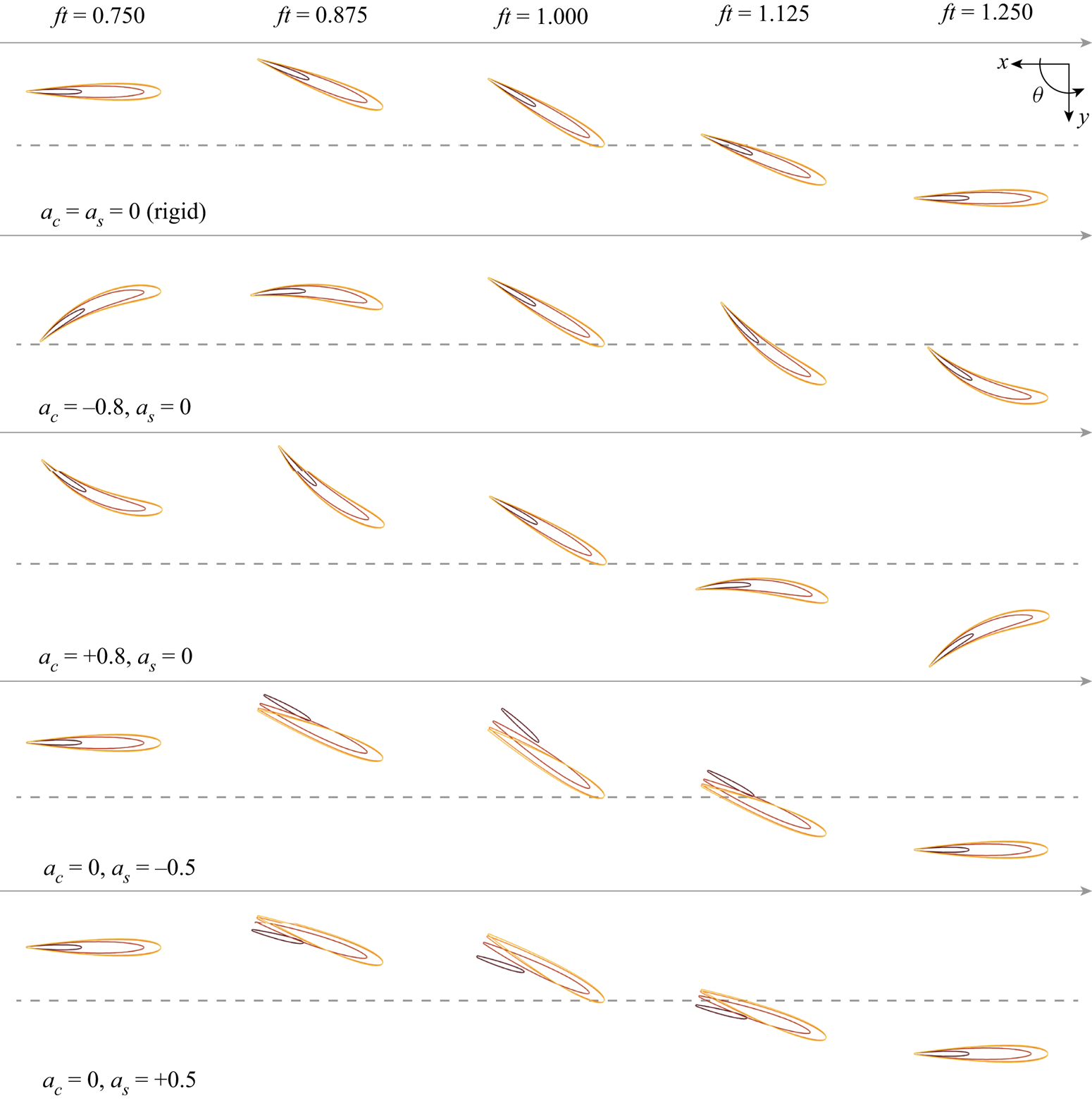
Combined with our choice of heaving and pitching kinematics, figure 2 demonstrates the effect of positive and negative values of our two parameters  $a_c$ and
 $a_s$ on the fin shape variations, with
 $a_c = a_s = 0$ corresponding to a rigid fin. Additional 3-D views of the different shapes mimicking the curvature combinations and time stamps plotted in figure 2 are provided in appendix B.4 in the supplementary material.
Horizontal cross-sections taken at  $z/C = \{0.000, 0.175, 0.350, 0.525\}$ under various curvature regimes obtained within the 2-D parametrization (
 $a_c, a_s$).

3.3. Numerical settings
To construct the fin shape we use numerical parameters  $\epsilon ^{{dist}}=5 \times 10^{-8}$ and
 $\epsilon ^{{smth}} = 8 \times 10^{-7}$, and we demonstrate in appendix C.1 of the supplementary material that the associated time-varying mid-surface area changes are negligible.
The spatial resolution throughout the simulations is set by a uniform grid spacing of  $\Delta x = C/200$, following the grid convergence analysis presented in appendix C.2 in the supplementary material. The temporal resolution is fixed by a Lagrangian Courant–Friedrichs–Lewy (LCFL) time step constraint of
 $\text {LCFL} = 0.1$ (van Rees et al. Reference van Rees, Leonard, Pullin and Koumoutsakos2011). The computational domain increases dynamically to capture the support of the vorticity field as the wake grows.
The time-varying thrust, lift and power coefficients are defined as
 \begin{gather} C_T(t) = \frac{T(t)}{0.5 \rho A U_{\infty}^{2}} , \end{gather}
 \begin{gather}C_L(t) = \frac{L(t)}{0.5 \rho A U_{\infty}^{2}} , \end{gather}
 \begin{gather}C_P(t) = \frac{P(t)}{0.5 \rho A U_{\infty}^{3}} , \end{gather}
where  $T$,
 $L$ and
 $P$ are the thrust, lift and power computed from the flow field at a given time step following equations (2.19), (2.20) and (2.22), and
 $A$ is the reference fin area taken as twice the mid-surface area to approximate the wetted surface area.
The imposed rigid-body kinematics are ramped up during the first flapping period through multiplication with a quarter period of a sine function. We then simulate until non-dimensional time  $ft = 1.5$, and compute the cycle-averaged thrust and power coefficients (
 $\overline {C_T}$ and
 $\overline {C_{P}}$, respectively) over the last simulated half-cycle (
 $1 \leqslant ft \leqslant 1.5$)
 \begin{gather} \overline{C_T} = \int_{t=1/f}^{1.5/f} C_T(t) \,\mathrm{d}t , \end{gather}
 \begin{gather}\overline{C_P} = \int_{t=1/f}^{1.5/f} C_P(t) \,\mathrm{d}t . \end{gather}
We can then define the propulsive efficiency as
 \begin{equation} \eta = \frac{ \overline{C_T}}{\overline{C_P}} . \end{equation}
Appendix C.3 of the supplementary material validates this choice of measurement window, and demonstrates that, with our chosen ramp up, the force and power coefficients have already reached their steady-state values after the first cycle.
In the following, we will primarily rely on  $\overline {C_T}$,
 $\overline {C_P}$ and
 $\eta$, as defined above, as metrics for hydrodynamic performance.
4. Effect of curvature variations on hydrodynamic performance
Using the numerical framework and heave/pitch kinematics as described above, we simulated a set of flapping fins with curvature parameter variations  $a_c\in [-0.4,0.8]$ and
 $a_s \in [-0.5,0.75]$, with
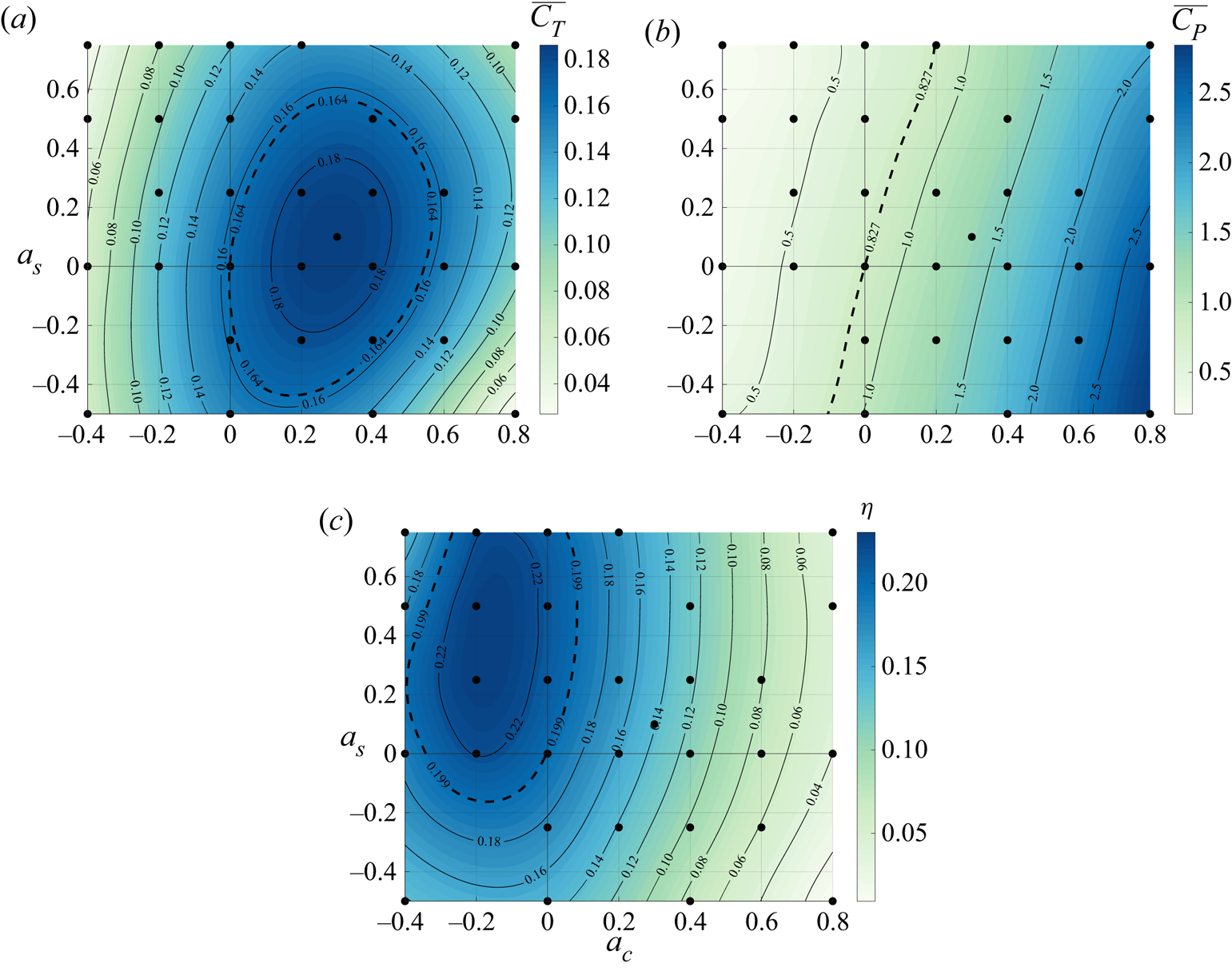
 $a_c=a_s=0$ corresponding to a rigid fin. For each simulation, we recorded the mean thrust and power coefficients, and computed the propulsive efficiency. These results are shown as contour plots in figure 3, visualizing the effect of changing the curvature parameters on the hydrodynamic performance metrics.
Cycle-averaged thrust (a) and power (b) coefficients and efficiency (c) results from Navier–Stokes simulations (black dots), and an interpolated contour plot based on these results, as a function of the two curvature parameters  $a_c$ and
 $a_s$.

Based on figure 3, the maximum computed thrust occurs at  $a_c = 0.3$ and
 $a_s = 0.1$, and is approximately 15 % larger than that for a rigid fin. Further, we can see that positive values of
 $a_c$ generally improve the thrust coefficient up until the maximum, after which the thrust coefficient decays. The effect of spanwise curvature variations, as measured by
 $a_s$, is less pronounced than the chordwise curvature effect.
For efficiency, the maximum occurs at  $a_c = -0.2$ and
 $a_s = 0.25$, leading to approximately 18 % improvement over the rigid fin. The increase in efficiency is driven by a strong decrease of the power coefficient as
 $a_c$ decreases. We also observe a small reduction of the power with increasing spanwise curvature parameter, so that the maximum efficiency is achieved at positive
 $a_s$.
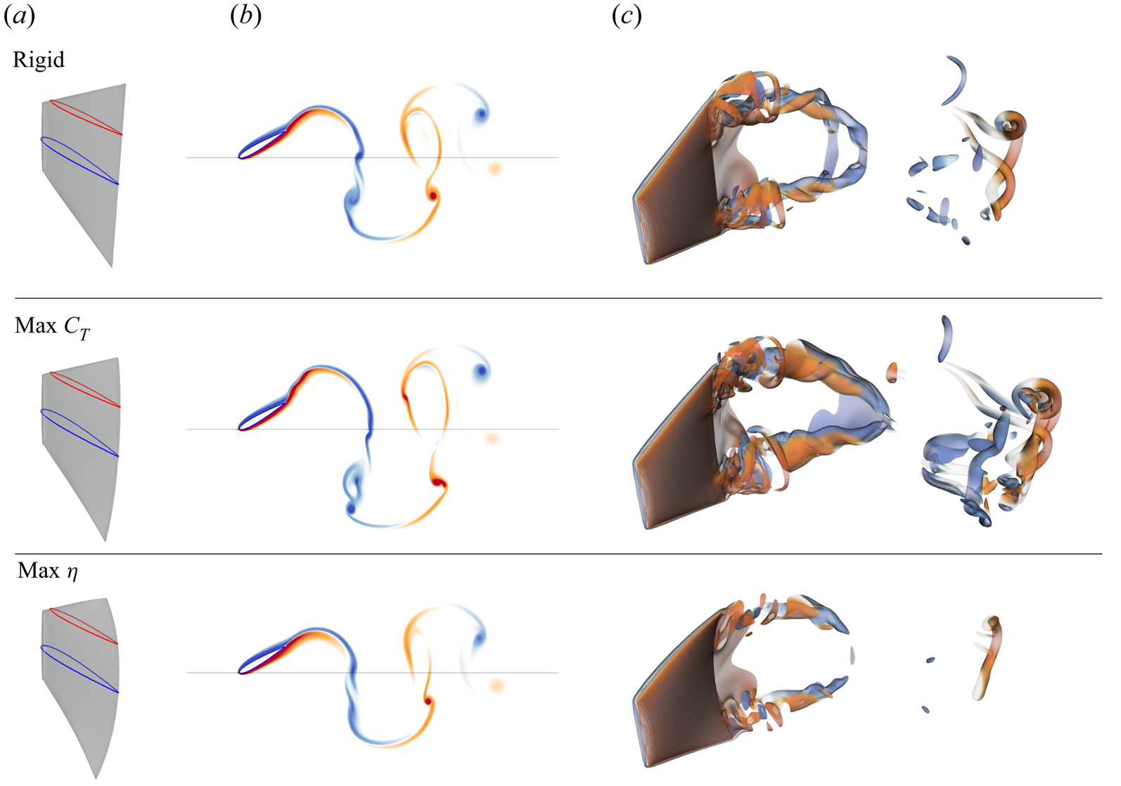
Figure 4 shows the vortical structures at  $ft =1.5$ for the rigid fin, and the conditions corresponding to maximum computed thrust and maximum computed efficiency, respectively. We observe an increase in the intensity of the vortices shed from the fin for the maximum thrust, whereas the maximum efficiency case has a much smaller wake signature.
Fin shape (a),  $\omega _z$ vorticity field at
 $v=0$ (b) and 3-D vorticity field (c) for the rigid configuration (top,
 $a_c=0.0$,
 $a_s=0.0$), the maximum thrust configuration (middle,
 $a_c=0.3$,
 $a_s=0.1$) and the maximum efficiency configuration (bottom,
 $a_c=-0.2$,
 $a_s=0.5$), all at
 $ft=1.5$. The 3-D flow structures are visualized using vorticity magnitude, and both 2-D and 3-D visualizations are coloured by
 $\omega _z$. Animations of the flow fields of these three cases are given in the supplementary material as movies 2–4, respectively.

5. Analysis of the effect of curvature variations
In the following two subsections, we investigate in detail the effect of our chordwise and spanwise curvature parameters on the hydrodynamic performance of the fin, guided by the above observations.
5.1. Effect of chordwise curvature parameter  $a_c$

As shown in the previous section, chordwise deformation has the largest impact on both thrust and power, which is qualitatively consistent with previous results (Zhu & Shoele Reference Zhu and Shoele2008; Esposito et al. Reference Esposito, Tangorra, Flammang and Lauder2012). In this section we focus on the underlying mechanisms by considering only configurations with  $a_s=0$.
Geometrically, by varying  $a_c$, the mid-surface plane rolls over a vertical cylinder of radius
 $C/a_c$. As
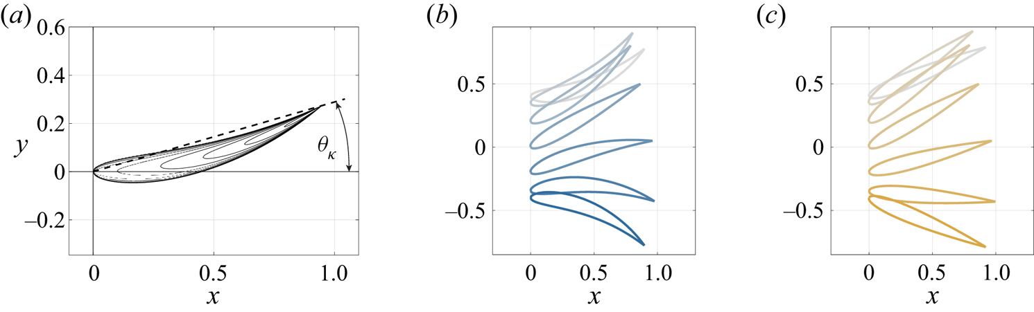
 $a_c$ increases, this means the curving fin is different from the reference rigid fin in two aspects. First, the line connecting leading and trailing edge of the fin also undergoes additional lateral trailing-edge excursions (see figure 5). Second, on top of the modified trailing-edge kinematics, the fin experiences a camber-like deformation. The former effect can be described as an additional pitching contribution, on top of the reference pitching kinematics (3.2). Based on the deformation mode considered, this additional pitching term can be derived as
 $\theta _{\kappa }(t) = 0.5 a_c \sin (2{\rm \pi} f t)$. With this insight, we can then decompose the effect of
 $a_c$ into two characteristics: the first increases the pitch variations of the reference rigid fin with
 $\theta _{\kappa }(t)$, and the second adds the chordwise curvature on top of this rigid-body motion without affecting the leading- and trailing-edge locations.
(a) Horizontal cross-sections at  $f t=1.25$ of the curved fin with
 $a_c=0.8$ and
 $a_s = 0$. (b,c) Cross-sections at
 $v=0$ of the curved (b) and
 $\kappa$-pitch (c) configurations during the down-stroke half-cycle, visualized at seven equidistant time instances between
 $ft = 0.25$ (lightest) and
 $ft = 0.75$ (darkest).

We investigate the first effect by simulating a rigid fin undergoing altered pitch kinematics given by
 \begin{equation} \theta^{\kappa\text{-pitch}}(t) ={-} A_\theta \cos(2 {\rm \pi}f t) + 0.5 a_c \sin(2{\rm \pi} f t) , \end{equation}
while keeping the geometry and heave kinematics the same as the reference rigid fin. This configuration, which we denote as the  $\kappa$-pitch case, is also parametrized by
 $a_c$, although the fin does not undergo any curvature variations.
Figure 6 compares the thrust, power and efficiency of the curved and  $\kappa$-pitch configurations for the range of
 $a_c$ studied, where again
 $a_c = 0$ corresponds to the rigid fin with unaltered pitching kinematics. We observe that the
 $\kappa$-pitch case qualitatively reproduces the effect of
 $a_c$ on the mean thrust coefficient, leading to a decrease in thrust for negative values and the existence of a maximum at finite
 $a_c > 0$. The effect of
 $a_c$ on power and efficiency are also qualitatively comparable between the curved and
 $\kappa$-pitch configurations. This provides our first insight into why the chordwise curvature variations lead to increased thrust coefficient.
Cycle-averaged thrust coefficient (a), power coefficient (b) and efficiency (c) as a function of the chordwise curvature parameter  $a_c$, for the fin with curvature variations (in blue) and the rigid fin with
 $\kappa$-pitch kinematics (in orange).

However, quantitatively there is a significant increase in the maximum thrust coefficient achieved by the  $\kappa$-pitch case over the optimally curved case. Further, the peak thrust for the
 $\kappa$-pitch fin occurs at
 $a_c = 0.95$, vs
 $a_c = 0.28$ for the curved fin. Since power consumption is approximately equal between the two cases, the efficiency of the
 $\kappa$-pitch fin at high thrust values (
 $a_c > 0$) is significantly higher than for the curved fin. The optimal efficiency, on the other hand, is achieved at much lower thrust values – here, the curved fin outperforms the
 $\kappa$-pitch fin slightly, which we will discuss more at the end of this subsection.
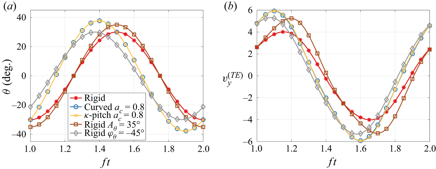
To understand why the  $\kappa$-pitch kinematics are able to practically double the thrust coefficient (at
 $a_c = 0.8$) of the reference rigid fin (
 $a_c = 0$), figure 7(a) compares the pitch angle variations as a function of time for the reference rigid fin (in red) and the
 $\kappa$-pitch fin (in orange). Note that, by construction, the pitch angle variations of the
 $\kappa$-pitch configuration (in orange) are identical to that of the curving fin (in blue) at equal values of
 $a_c$. The plot shows how, compared with the reference rigid fin, the
 $\kappa$-pitch configuration not only achieves an increase in maximum pitch angle, but also affects the phase shift with the heave motion. In fact, we can estimate the effective pitch amplitude and phase values of the
 $\kappa$-pitch kinematics, using (5.1), as follows:
 \begin{gather} A_{\theta}^{\kappa\text{-pitch}} = \max(\theta) = \sqrt{A_{\theta}^{2} + \left(0.5 a_c\right)^{2}}, \end{gather}
 \begin{gather}\varphi_{\theta}^{\kappa\text{-pitch}} = 2{\rm \pi} \left( t_{max(\theta)} - t_{max(y)} \right) = \frac{\rm \pi}{2} - \arctan\left(\frac{0.5 a_c}{A_{\theta}}\right) . \end{gather}
For  $a_c=0.8$, where the
 $\kappa$-pitch kinematics achieve maximum thrust, we then find
 $A_{\theta }^{\kappa \text {-pitch}} = 37.8^{\circ }$ and
 $\varphi _{\theta }^{\kappa \text {-pitch}} = -52.6^{\circ }$.
Pitch angle (a) and trailing-edge lateral velocity (b) during a flapping cycle, for the rigid fin with reference kinematics (red), the fin with curvature variations  $a_c = 0.8$ (blue) and the rigid fin with
 $\kappa$-pitch kinematics using
 $a_c = 0.8$ (orange). Also shown are the rigid fin results with harmonic pitch variations with amplitude
 $A_\theta = {35}^{\circ }$ (brown) and with phase shift
 $\varphi = -{45}^{\circ }$ (grey).

When analysing the isolated effect of pitch amplitude and phase angle variations on our reference rigid fin, we see why the altered kinematics of the  $\kappa$-pitch configuration are virtuous. Appendix D.1 in the supplementary material shows that changing the phase shift from
 $-90^{\circ }$ to
 ${-45}^{\circ }$ doubles the thrust coefficient of the reference rigid fin, and an independent increase in pitch amplitude from
 ${30}^{\circ }$ to
 ${35}^{\circ }$ also leads to a modest increase in thrust. The corresponding pitch angle variations are shown in figure 7(a) as the grey and brown lines, respectively. The
 $\kappa$-pitch configuration then combines a pitch amplitude and pitch phase shift that are very close combinations of the individual optimal values for the reference rigid fin with sinusoidal pitch variations. As a side note, we observe also in appendix D.1 in the supplementary material that in terms of efficiency, the
 ${-90}^{\circ }$ phase angle is optimum, consistent with the findings of Read et al. (Reference Read, Hover and Triantafyllou2003).
To summarize results so far, we have observed that the original curvature variation, as dictated by  $a_c$, provides an altered pitching kinematics that increases the mean thrust coefficient achieved by the fin. We can reproduce this effect with a rigid fin, both using a combined effective amplitude and phase shift, as well as through independent variations of amplitude and phase shift. Both indicate that the significant driver in thrust increase is the phase shift change from
 ${-90}^{\circ }$ to approximately
 ${-50}^{\circ }$. In the remainder of this subsection we will focus on two open questions: the first asks why this altered pitching kinematics improves performance, and the second asks why the
 $\kappa$-pitch fin provide significantly larger thrust values for all
 $a_c > 0$ compared with the curving fin.
We answer the first question by examining the trailing-edge (TE) lateral velocity as shown in figure 7(b) for all cases discussed above. From (3.1), (3.2), and (5.1), we find that the maximum TE velocity, scaled by chord and frequency, is  $v_{y,max}^{(TE)} \approx 2{\rm \pi} \sqrt {(\tilde {A}_y + 0.5 a_c)^{2} + A_\theta ^{2}}$. For our parameter choices, the amplitude of the TE lateral velocity increases approximately 1.45-fold between the reference rigid fin and the
 $\kappa$-pitch configuration with
 $a_c = 0.8$, leading to an increase in mean thrust coefficient by a factor of 2.1. This is consistent with the added mass effect for pitching fin propulsion (Garrick Reference Garrick1936; Gazzola, Argentina & Mahadevan Reference Gazzola, Argentina and Mahadevan2014b; Smits Reference Smits2019) which predicts that the thrust coefficient is proportional to the square of the lateral velocity. The TE velocity amplitude does not solely predict performance: the timing of maximum TE velocity compared with the fixed heaving kinematics also affects the thrust coefficient. This is a much more subtle interaction, however, that would require further investigation.
The second open question concerns the difference between the fin with curvature variations and the  $\kappa$-pitch configuration, for the same value of
 $a_c$. To address this, we plot the time evolution of the difference in thrust and lift coefficients between the curving fin and the
 $\kappa$-pitch configuration in figure 8(a). For reference, the time evolution of the individual force coefficients is included in appendix D.2 in the supplementary material. From figure 8(a), we can identify two reasons for the lower thrust coefficient of the chordwise curving fin compared with the
 $\kappa$-pitch fin. First, for times
 $1 \leqslant ft \leqslant 1.2$, corresponding to the second half of the upstroke just before reversal of the heave kinematics, the difference in
 $C_T$ is large whereas the difference in
 $C_L$ is relatively small. This implies an increased drag force on the curving fin, consistent with the curved profile in this part of the stroke where the fin becomes aligned with the inflow. The images on the top row of figure 8(b) confirm that the total force vector is angled more vertically for the curved case compared with the
 $\kappa$-pitch case. Second, for times
 $1.25 \leqslant ft \leqslant 1.5$, corresponding to the first part of the downstroke after the heave motion has reversed, we observe that the
 $\kappa$-pitch configuration experiences both larger thrust and larger lift coefficients. This means that the overall force vector on the fin is larger for the
 $\kappa$-pitch fin. We attribute the decreased force of the chordwise curving fin to the camber, which essentially is ‘reversed’ as the trailing edge slopes upwards, in the direction of the force resultant. The images on the bottom row of figure 8(b) corroborate this visually. Both of these effects are repeated every
 $ft = 0.5$ times due to the symmetry of the up- and down-strokes. These two reasons (additional profile drag and reverse camber) lead to the reduced performance of the chordwise curving fin compared with the
 $\kappa$-pitch rigid fin.
(a) Difference in thrust and lift coefficients between the curved and  $\kappa$-pitch configurations with
 $a_c=0.8$. Solid and dashed lines identify the upstroke and downstroke half-cycles, respectively. (b) Vorticity contours at the centre plane. Incident velocity vector and its horizontal and vertical components annotated at the LE (
 $\boldsymbol {u} = [U_{\infty }, -\dot {y}]$). Fluid force vector and its horizontal and vertical components annotated at fin centroid (
 $\boldsymbol {F} = [-T,L]$).

So far, this subsection has focused on the regime  $a_c > 0$, where significant gains in the mean thrust coefficient are observed. However, our results also show that negative values of
 $a_c$ monotonically decrease the power required to move the fin, and increase the efficiency
 $\eta$. The power reduction is apparent from figure 9, showing the power components associated with heave and pitch, defined as
 $P^{(L)} = -L \dot {y}$ and
 $P^{(M)} = - \boldsymbol {M} \boldsymbol {\cdot } \dot {\boldsymbol {\theta }}$, respectively. The plot demonstrates that the power reduction is approximately equally distributed between the heave and pitch kinematics. The deformation-related power coefficient,
 $C_P^{def} = C_P - C_P^{T} - C_P^{M}$, decreases as well, but this reduction is relatively insignificant compared with the other two components. To distinguish the effects of fin camber and TE kinematics in the regime
 $a_c < 0$, we can revisit figure 6. Both the
 $\kappa$-pitch and the curving fins reduce their power coefficients equally, indicating that the power reduction at negative
 $a_c$ is due to the reduced TE velocity. However, only the curving fin demonstrates a peak in efficiency at
 $a_c < 0$, since the fin camber leads to a slight increase in thrust coefficient over the
 $\kappa$-pitch configuration for the same values of
 $a_c$. Consequently, the efficiency peak of the curving fin is higher than that of any of the rigid fins, and achieved at a negative
 $a_c$ value. Overall, this behaviour is consistent with intuition – negative values of
 $a_c$ correspond to curvature ‘with the flow’, i.e. qualitatively similar to elastic deformation, as well as a hydrodynamically beneficial camber induced during the thrust-generation part of the stroke.
Cycle-averaged power coefficient components linked to heave (a) and pitch (b) computed from Navier–Stokes simulations (black dots), and an interpolated contour plot based on these results, as a function of the two curvature parameters  $a_c$ and
 $a_s$.

5.2. Effect of spanwise curvature parameter $a_s$

As discussed previously, spanwise curvature variations as parametrized by  $a_s$ predominantly affect the cycle-averaged power coefficient, which monotonically decreases with increasing values of
 $a_s$ within the range of curvatures simulated. Figure 9 shows that this power reduction originates almost exclusively from the pitch kinematics. In this section we will investigate this effect further, considering only configurations with
 $a_c=0$.
Similar to the chordwise curvature in the previous section, the spanwise curvature can be decomposed into two components: the spanwise twisting of otherwise straight rays, and the actual curving of the rays without further affecting their TE locations. We can isolate the former component starting from a rigid fin, and adjust the pitch variation across the height of the fin to match the LE–TE direction associated with the  $a_s$ curvature profile
 \begin{equation} \theta^{\kappa\text{-twist}}(v, t) = \left( - A_\theta + 0.5 a_s v^{2} \right) \cos(2 {\rm \pi}f t) . \end{equation}
We name this configuration  $\kappa$-twist, and note that we have to relax the membrane inextensibility constraint to accomplish the resulting shape.
Figure 10 compares the behaviour of the deformed fin with that of the  $\kappa$-twisted fin, across the range of
 $a_s$ values considered. The qualitative trends are similar, with increasing
 $a_s$ values increasing thrust, decreasing power and increasing efficiency for both the curving and the
 $\kappa$-twist fins. This demonstrates that the spanwise twist is the predominant factor underlying these hydrodynamic characteristics, rather than the actual curvature of the rays. We observe a slight increase in peak efficiency of the curving fin compared with the
 $\kappa$-twist configuration indicating that here, again, the camber can improve efficiency.
Cycle-averaged mean thrust coefficient (a), mean power coefficient (b) and efficiency (c) as a function of the spanwise curvature parameter  $a_s$, for the fin with curvature variations (blue) and the
 $\kappa$-twist configuration (green).

To understand the effect of  $\kappa$-twist kinematics on the performance, we can examine (5.4) further. For our spanwise curvature parametrization, the spanwise curvature variations are in phase with pitch but of the opposite sign. Positive values of
 $a_s$ then decrease the effective pitch angle, and vice versa, with the maximum effect noticeable at the top and bottom of the fin, away from the centre plane. This is observed in figure 11, showing that the pitch angle and TE velocity amplitude of the top ray during a flapping cycle significantly reduces when
 $a_s$ is increased. Consequently, since the outer parts of the fin undergo smaller pitching amplitudes, the associated power reduction is observed predominantly in the pitching component
 $C_P^{M}$. Further, the reduced power and increased efficiency with increasing spanwise curvature parameter are consistent with the smaller vortical signature of the wake, as shown in figure 12. The twisted configuration with
 $a_s = 0.5$ leads to significantly smaller tip vortices shed from the outer edges of the fin, compared with both rigid and
 $a_s = -0.5$. Lastly, we note that the qualitative deformation of the fin when
 $a_s > 0$ is intuitively consistent with the elastic deformation of a finite-span flapping fin: the outer edges will curl inwards during the heave reversal, lagging behind the central rays of the fin. Together with the previous results, this provides further indication that the curvature variations of passively deforming 3-D fins can lead to higher propulsive efficiency than those of rigid fins, as measured solely through hydrodynamic performance.
Pitch angle (a) and TE lateral velocity (b) of the top ray during a flapping cycle for the rigid fin (red), and the fin with spanwise curvature variations  $a_s = -0.5$ (purple) and
 $a_s = +0.5$ (yellow).

Vorticity field of the fin for the sole spanwise curvature configuration with  $a_s=-0.5$ (a) and
 $a_s=0.5$ (b), both at
 $f t =1.5$ and with
 $a_c = 0$. The flow structures are visualized using vorticity magnitude and coloured by
 $\omega _z$.

6. Concluding remarks
Our results describe and analyse the hydrodynamic effects of leading-edge actuated curvature variations on flapping fin performance. We have demonstrated that such actuation can lead to an increase in efficiency by about  $18$% and mean thrust coefficient by approximately
 $15\,\%$ compared with a rigid fin. Within our parametrization, thrust is maximized when considering some degree of positive curvature, both chordwise and spanwise, while efficiency benefits from negative chordwise and positive spanwise curvature deformations. Throughout, the chordwise parameter dominates the hydrodynamic performance, with spanwise curvature variations only providing small additional changes in performance. Exploratory investigations discussed in appendix E demonstrate that all trends found are robust to changes in planform shape, and the effect of chordwise curvature is reproduced at a higher Strouhal number of
 $St = 0.6$, as well as in 2-D simulations. Compared with existing literature, our study confirms that passive spanwise deformations can reduce thrust and propulsive efficiency (Liu & Bose Reference Liu and Bose1997; Zhu Reference Zhu2007), that (small) active spanwise deformations can increase thrust (Esposito et al. Reference Esposito, Tangorra, Flammang and Lauder2012) and that chordwise flexibility can increase efficiency (Prempraneerach et al. Reference Prempraneerach, Hover and Triantafyllou2003; Zhu Reference Zhu2007). We do note, however, that one-to-one comparisons between our results using imposed curvature variations and prior studies with elastic fin deformations are challenging whenever the time-varying elastic fin deformations are not explicitly provided.
In our analysis, we show that leading-edge curvature actuation not only introduces a camber in the fin cross-section, but also affects the TE kinematics. To investigate these two effects separately, we investigated rigid fins without camber whose pitch kinematics are tuned to the TE kinematics of the curving fin. The analysis shows that the increase in thrust due to chordwise curvature against the flow can also be obtained by a rigid fin with modified pitching kinematics; in fact, the rigid fin outperforms the curving fin, because the camber associated with the chordwise curvature variations is hydrodynamically disadvantageous. On the other hand, the increase in efficiency due to curvature with the flow is predominantly caused by the hydrodynamically advantageous camber in this regime, together with a small effect of spanwise twist that reduces the intensity of the shed tip vortices. Overall, throughout this work we have found that the performance benefits of fins with leading-edge curvature actuation can in large part be reproduced by rigid fins with suitably adapted pitch kinematics, ignoring the small benefits of camber changes on efficiency. This poses an interesting question, namely to compare the benefits of these different types of actuation: the trade-off between modulating the phase and amplitude of leading-edge curvature variations, versus those of the pitch kinematics. In nature, the kinematics of the flapping fin are rarely as simple as the idealized case considered here, since lateral motions and body undulations combine to give rise to what we model here as heaving and pitching motions in a uniform inflow. A possible benefit of leading-edge curvature actuation is then that it provides a localized approach that can be controlled independent of the body and swimming motions. This could improve the swimmer's versatility and responsiveness, enabling it to use local muscle actuation to deliver more thrust or reduced power without adapting the body undulations that give rise to the pitching kinematics. Further, specifically for the high-efficiency curvature regimes considered here, part of our imposed deformations could be realized passively through elastic deformations to the hydrodynamic loading, making such swimming modes simpler to control. Taken together, a combination of the right structural design of the fin together with leading-edge curvature actuation could provide a simple, versatile, and responsive way to achieve the hydrodynamic benefits described in this work.
Lastly, we note two distinct other contributions of this work. First, we have exploited our geometric and numerical framework to construct fin shapes with imposed normal curvature profiles. Generally, the framework transforms an arbitrary normal curvature description  $\kappa ^{n}(u,v,t)$, with appropriate initial conditions, into a three-dimensional geometry. The geometry can then be combined with arbitrary, time-dependent rigid-body translations and rotations to model any heaving, pitching or other rigid-body motion. In this work the framework is tailored to model caudal fins, but future work will generalize it to describe the geometry of other fin types with inextensible mid-surfaces, such as those in rays and skates. Second, we have demonstrated that rigid fins with modified kinematics can be used as a qualitative and, to some extent, quantitative proxy for fins with leading-edge curvature actuation. Future work will be aimed at further separating the effect of TE kinematics from the changes in camber of the fin, and to design curvature actuation patterns that can fully exploit the benefits of both.
Supplementary material
Supplementary material and movies are available at https://doi.org/10.1017/jfm.2021.469.
Funding
This work was supported by the Chang Fund from the MIT School of Engineering Research Support Committee. W.v.R. thanks the American Bureau of Shipping for support through a Career Development Chair, and the MIT Sea Grant College Program for support through the Doherty Professorship in Ocean Utilization.
Declaration of interests
The authors report no conflict of interest.