Introduction
The current wireless system's fragmentation, limited bandwidth, and insufficient channel capacity have forced scientists and researchers to use an unutilized mm-wave frequency band in fifth generation (5G) communication systems [Reference Ghosh, Maeder, Baker and Chandramouli1, Reference Abdel-Fatah, Hamad, Swelam, Allam and Mohamed2]. The forthcoming 5G communication systems would fulfill not only the explosively growing requirements for the billions of devices linked in our world with high data rates, trustworthiness, and low power consumption, but also the full capacity of digital technologies such as smart communities, virtual world, and autonomous cars [Reference Vannithamby and Talwar3]. Researchers from around the world are working on developing and standardizing 5G communication systems. However, it is important to eliminate crucial limitations of the mm-wave spectrum, such as signal fading, atmospheric absorption, and path loss attenuations, which are more severe with a single antenna. Furthermore, the challenges of multiple-input multiple-output's (MIMO) antenna design are designing closely packaged antenna elements with reduced reciprocal coupling and high isolation, which improves the antenna efficiency. In addition to previously mentioned, one of the key challenges with the 5G communications system is the correct orientation of the transmitter and receiver antennas. Antennas that are circularly polarized (CP) are excellent solutions to this issue [Reference Banerjee, Karmakar and Saha4, Reference Hussain, Jeong, Abbas, Kim and Kim5].
Several techniques are available in the literature to produce circular polarized radiation. Circular polarization techniques can be graded as single feed and dual feed. The latter offers a broader CP bandwidth, but includes a challenging feeding network and a relatively large scale [Reference Moubadir, Badaoui, Touhami, Aghoutane and El Ouahabi6, Reference Caso, Buffi, Pino, Nepa and Manara7]. Generating circular polarized radiation using a single-feed configuration requires slight perturbation of the antenna structure, and optimizing the location of the perturbation with respect to the feed to excite orthogonal modes, such as the slits, truncated corners, and slots [Reference Lam, Luk, Lee, Wong and Ng8, Reference Qing and Chen9]. Different design techniques, such as stubs and neutralization lines [Reference Ou, Cai and Qian10], polarization conversion isolator [Reference Cheng, Ding, Shao and Wang11], various parasitic elements [Reference Ahmed, Ghoname and Zekry12, Reference Li, Du, Takahashi, Saito and Ito13], metamaterials [Reference Abdelaziz and Hamad14, Reference Khajeh-Khalili, Honarvar, Naser-Moghadasi and Dolatshahi15], etc., were applied primarily in order to minimize mutual coupling in the MIMO antennas. However, these conventional perturbation techniques do not offer the efficient performance for the antennas in mm-wave frequencies. Therefore, in this paper, we present a novel technique for producing a circular polarization antenna using circular spiral structure. Additionally, for a complete improvement of this proposed CP antenna, we will use a novel double face logarithmic spiral metamaterial (LSMTM) superstrate that acts as a planar concave-concave lens for isolation, gain, and bandwidth improvements.
The most important and paramount goal in this paper, in addition to the full improvement of a CP antenna, is to use a systematic style methodology utilizing the theory of characteristic modes (TCMs) in designing and canceling random designs or so-called trial-and-error to obtain the results.
Characteristic mode analysis (CMA) has shown an understanding of the operating mechanism of the antenna [Reference Harrington and Mautz16–Reference Garbacz and Turpin18]. It exhibits natural electromagnetic resonance characteristics, including current distribution and a far-field radiation pattern [Reference Huang, Pan and Luo19]. These data can be used in the assessment of the antenna's effectiveness and may aid the process of performance optimization [Reference Khan and Chatterjee20–Reference Saraswat and Harish22].
Initially, the TCMs were introduced in [Reference Garbacz and Turpin18] by Garbacz and Turpin and subsequently updated in the 70s by Harrington and Mautz in the form of the process of the moment matrix [Reference Harrington and Mautz16, Reference Harrington and Mautz23]. The characteristic modes (CMs) can be used for the frequency resonance of the modes and to provide a physical insight into the radiation of the antenna. Each mode consists of a characteristic value or an angle that gives the knowledge of mode resonance and radiation behavior. CMs are realistic modes identified as a result of the following relation:

where X and R indicate the geometry's reactance and resistance, respectively, and λn is the eigenvalue corresponding to eigenvector Jn, this represents the n th mode's current density on the antenna surface.
Other important parameters from the CMA are the modal significance (MSn), and the characteristic angle (βn). The modal significance denotes the normalized amplitude of each modal current and determines the radiation performance of each mode. It is given by

where the characteristic angle models the phase difference between the characteristic current, Jn, and the associated characteristic field En. It is given by

In the former section of this paper, a substrate with non-zero tan δ was considered. However, for the CMA, only perfect electric conductors and ideal dielectric materials were employed since the CST Microwave Studio 2018 software is not able to perform the CMA with lossy materials. After applying the CMA to the structure, the results give the eigenvalue (λn), characteristic angle (βn), and modal significance (MSn) parameters over the desired frequency band. From these three parameters, one can explore the behavior of the concerned structure. When βn is for any mode close to 180 while λn is equal to 0 and the MSn is equal to 1; those modes radiate well at their resonant frequencies, otherwise, they store energy which indicates that βn is near 90° or 270° while λn is near 1 or −1.
This paper is organized mainly as follows: The antenna geometry is defined in section “Antenna geometry”. Sections “Antenna design procedure” and “Antenna analysis” explain the antenna design process, analysis and behavior of the logarithmic spiral superstrate metamaterial, as well as the methods of gain, bandwidth, and isolation improvement with a characteristic method analysis. The concept introduced is then verified by the experiment in section “Experimental verification”. A comparison with state-of-the-art works is presented in section “Comparison with state-of-the-art works”, which is followed by conclusion in section “Conclusion”.
Antenna geometry
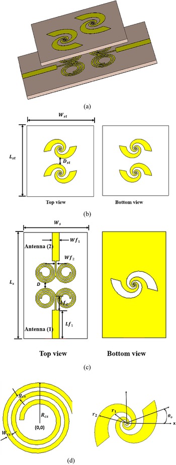
Figure 1 shows the design parameters and geometry of both the proposed two-element circular spiral MIMO antenna and the decoupling double-face LSMTM superstrate, which are structured on both sides of a Rogers RO4003C substrate of thickness 0.813 mm with εr = 3.38 and tan δ = 0.0027. For the proposed antenna, two identical circular spiral patches are sized and optimized to resonate at 28 GHz. To guarantee the best antenna efficiency, the edge-to-edge separation (D) is limited to 0.14λo. A quarter-wave impedance transformer feed is used to excite each antenna element. The antenna has an overall size of only 18 × 30 × 8.626 mm3 which corresponds to 1.68λo × 2.8λo × 0.805λo, where λo is free-space wavelength at 28 GHz. The parameters for the optimal performance of the antenna are obtainable in Table 1.
The geometry of the proposed LSMTM superstrate antenna: (a) perspective view of the proposed antenna, (b) LSMTM superstrate, (c) two-element circular spiral MIMO antenna, (d) zoomed circular and logarithmic spirals.

Optimum dimensions of the proposed antenna (in mm)

Antenna design procedure
The complete design process for the planned CP antenna is described in this section. For easy comprehension, it is separated into the following sub-sections.
Design of the circular spiral patch antenna
The design of the planned antenna begins with the simulation of a circular spiral patch antenna designed for 28 GHz operation. Instead of the traditional shapes of the patch such as the square, rectangular, triangle, and circular shape previously used in literature; in this study, a circular spiral patch to obtain circular polarization more easily is used. The dimensions of the circular spiral patch at the central frequency are calculated as indicated in Table 1. It is evident from Fig. 2 that the coupling is stronger (S 21 = −14 dB) when the two spiral antenna elements are closer to each other; meanwhile, the antenna system performance can deteriorate significantly, such as narrow bandwidth and low gain, that is why the LSMTM structure and characteristic mode analysis is used for the full enhancement of this CP antenna.
Simulated S-parameters of the initial circular patch antenna.

In order to improve the bandwidth and performance of the antenna, the ground plane is defected with a LSMTM unit cell as shown in Fig. 1(c). The MTM unit cell's basic architecture consists of a dual-arm logarithmic spiral in opposite rotation direction's structure, where the inner radius, outer radius, and the incremental angle are configured in order to achieve desirable electromagnetic properties close to the designed antenna's resonance. As a result, the MTM unit cell's dimensions have been parametrically optimized in order to achieve high reflection and transmission characteristics close to the 28 GHz frequency. The standard logarithmic spiral is designed on the basis of equations given below [Reference Balanis24]:


where r 1 is the inner radius, r 2 is the outer radius, ro is the initial radius, θ is the incremental angle, a is the progression factor, and θ o is the phase shift of the spiral.
The reflection (S 11) and transmission (S 21) coefficients are obtained by simulating the LSMTM unit cell in CST Microwave Studio within suitable boundary conditions, which is then used to extract the effective material parameters (permittivity and permeability) using the algorithm developed in [Reference Szabó, Park, Hedge and Li25]. Figure 3 depicts the boundary conditions and floquet ports that were applied to the proposed LSMTM unit cell. When floquet ports are applied to the LSMTM unit cell, it gives the result of an infinite periodic structure (superstrate) solution in free space. As a result, there is no need to design an array of the periodic structures; instead, a single unit cell provides a complete solution. Based on Babinet's principle and the duality concept, the complementary LSMTM that is graved from the ground plane is the negative image of LSMTM, but the basic mechanism is the same for both resonators.
Simulation setup of the LSMTMT unit cell.

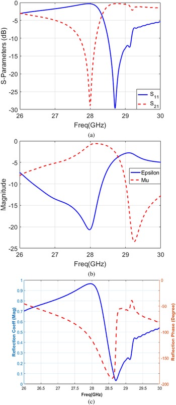
Figure 4(a) displays the simulated results of the scattering parameters S 11 and S 21 of the proposed LSMTM unit cell. Figure 4(b) shows the extracted unit-cell parameters which show that both the relative permittivity and permeability in the operating band were negative, justifying the condition that the proposed logarithmic spiral unit cell is a metamaterial behaved. As shown in Fig. 4(c), the unit cell exhibits high reflection magnitude over the desired band and flat reflection phase. These characteristics of the proposed logarithmic spiral confirm that as the reflection magnitude approaches unity, the antenna gain can be substantially increased [Reference Hamad and Abdelaziz26].
Proposed LSMTM unit cell, (a) S-parameters, (b) extracted metamaterial parameters, and (c) performance of the proposed unit cell.

To demonstrate the filtering characteristics of the band-gap LSMTM unit cell, the dispersion diagram analysis is utilized. The proposed LSMTM unit cell's filtering properties are demonstrated using Eigenmode analysis using the CST Microwave Studio. Figure 5 depicts the corresponding Brillouin diagram plotted along the Г-X axis of the proposed unit cell. From Fig. 5, the proposed LSMTM unit cell has a bandgap zone within the operating frequency band with an extensive rejection band of 2.6 GHz, which can play a strong role in improving the isolation between the two-port circular spiral MIMO patch antenna.
Dispersion analysis diagram of the proposed LSMTM unit cell.

As a result of the graved LSMTM unit cell on the ground plane, the bandwidth of the planned 28 GHz resonant antenna significantly improved. Figure 6 shows that there is a considerable increase in bandwidth up to 1.15 GHz, while the mutual coupling is reduced to −24 dB. The LSMTM unit cell on the ground plane increases the fringing field which introduces parasitic capacitance. This parasitic capacitance increases the coupling between the conducting patches and the ground plane which is responsible for the enhancement of the bandwidth and at the same time the LSMTM unit cell
Simulated S-parameters of the defected ground plane antenna with a LSMTM unit cell.

Design of double face LSMTM superstrate-based CP spiral patch antenna
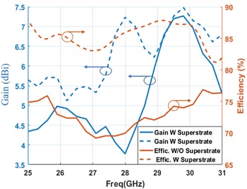
The novel double-face superstrate designed using the proposed logarithmic unit cell acts as a high reflective concave-concave lens to focus the propagating waves in a directive pattern in that way increasing the broadside gain of the circular spiral patch antenna. The proposed superstrate is shown in Fig. 1(b), in which the logarithmic unit cells are spaced by a separation of 0.093λo and they rotated at an angle of 28° clockwise for improved antenna isolation. The overall dimensions of the LSMTM superstrate layer are 18 × 20 mm2, and it is placed at a distance (Dst) of 6.5 mm above the conventional circular spiral patch antenna elements. This distance is found to be the best position for the superlative performance of the proposed antenna. Figure 7 displays the proposed antenna's simulated S-parameters when the antenna 1 is excited. The simulation results at resonant frequency show about 32 dB isolation enhancement between the two ports of the MIMO circular patch antenna (S 21 improved from −16 to −48 dB). The gain and efficiency versus frequency for the proposed circular spiral MIMO antenna with and without LSMTM superstrate are plotted in Fig. 8 to check the argument that the antenna gain and efficiency increase as the beam becomes more focused. In Fig. 8, the gain improved from 3.77 up to 7.24 dBi, and the radiation efficiency upgraded from 67 to 86%, which proves the work of this LSMTM superstrate as a planar concave-concave lens.
Simulated S-parameters of the proposed LSMTM superstrate MIMO antenna system.

Gain and efficiency of the MIMO circular patch antenna with and without LSMTM superstrate.

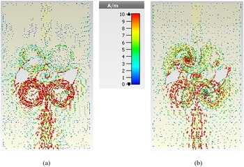
Figure 9 depicts the surface current distribution of the proposed two-port circular spiral MIMO patch antenna to validate the influence of the LSMTM superstrate structure to reduce mutual coupling. It can be seen from Fig. 9(a) that, in the absence of the LSMTM superstrate, when antenna 1 is excited and antenna 2 is terminated with a 50 Ω load, the current is distributed on the center portion of antenna 2, with radiation occurring from the edges of the antenna, and thus mutual coupling due to excitation of antenna 1 occurs at antenna 2. With the LSMTM superstrate structure placed above the two-port circular spiral MIMO patch antenna, the coupled field between antenna elements is concentrated mainly on the superstrate's unit-cell surface, nullifying the coupling field and improving the isolation between antenna elements significantly.
Surface current distribution (a) without LSMTM superstrate, (b) with LSMTM superstrate.

Figure 10 shows the simulated results from both CST and HFSS software of the axial ratio against the frequency of the proposed circular spiral-shaped two-element MIMO patch antenna. Figure 10 indicates the simulated 3 dB axial ratio bandwidth was found to be 1.4 GHz (27.4– 28.8 GHz) which is suitable for device-to-device 5G wireless communications. A minimum axial ratio of approximately 0.92 dB at the operating frequency of 28 GHz is achieved, showing that the obtained circular polarization is quite good, whereas the perfect circular polarization has an axial ratio between 1 or 0 dB and acceptable up to 3 dB.
Simulated axial ratio (dB) of the proposed circular spiral-shaped MIMO patch antenna.

Antenna analysis
Analysis of the mechanism of the LSMTM superstrate for the antenna performance enhancement
It is demonstrated in Fig. 11 that a traditional planar antenna with a microstrip line fed in the near-field produces spherical-phase radiation that may be converted to an in-phase planar by employing the double-face LSMTM superstrate on the top of the traditional antenna, hence boosting the gain. Therefore, in this section, the theories of surface impedance and transmission line will be applied, which allow the calculation of an incident plane wave on the superstrate layer. The proposed antenna has four layers as demonstrated in Fig. 11, which are in the following order: the traditional circular spiral patch antenna substrate of intrinsic impedance η 1, the air with intrinsic impedance η o, the double-face LSMTM superstrate with intrinsic impedance η 2, and the air with intrinsic impedance η o.
Side view of the proposed LSMTM superstrate antenna.

This spherical wave has input surface impedance Z in that can be written as:

where η o is the free space intrinsic impedance that can be calculated as $\eta _o = \sqrt {\varepsilon _o/\mu _o}$ , η 2 is the intrinsic impedance of the dielectric double-face LSMTM superstrate that can be written as $\eta _2 = \eta _o\sqrt {\varepsilon _{r2}/\mu _{r2}}$
 , and β is the dielectric superstrate phase constant that can be given by β = (2π/λ g).
It is essential to be mindful of the rays which go through the double-face LSMTM superstrate; only some of them travel in the backward direction, while the others are transmitted in the main forward direction. The mathematical formula for the power pattern yields the power-transmitted rays can be calculated as follows [Reference Feresidis and Vardaxoglou27]:

where R and ϕ s are the reflection coefficient and reflection phase of the double-face LSMTM superstrate, while ϕ g is the reflection phase of the ground plane, and f 2(θ) is the antenna pattern function in θ.
Conceptually, we consider θ = 0o as pointing in the forward direction. And then

The antenna resonant condition can be achieved when cos [ϕ s + ϕ g − (4π/λ)D st] = 1. So the resonant distance can be given as

As a result, the following formula can be used to calculate the maximum power in the direction of $\theta = 0^\circ$ :

where P 0 represents the forward power without the double-face LSMTM superstrate.
A simple formula for the proposed antenna gain loaded with double-face LSMTM superstrate can be calculated as:

In accordance with equation (11), the gain increases as the reflection coefficient R increases.
The proposed gain enhancement is explained by the cavity effect that occurs when the LSMTM superstrate is positioned conveniently above the patches. According to Snell's law of refraction, a medium having a low refractive index scatters electromagnetic waves away from the primary source and toward the normal of this surface. This feature considerably improves the directivity of the proposed MIMO antenna. The LSMTM superstrate acts as a highly reflecting surface, which results in a highly directional antenna. Additionally, the presence of the LSMTM superstrate makes the field distribution of the antenna more homogeneous, thus improving the overall gain of the MIMO antenna. The coupled field between antenna patches is concentrated mostly on the unit cell surface of the LSMTM superstrate, thus cancelling out the coupling field and considerably enhancing the antenna element isolation.
Placing the LSMTM superstrate above the patches at a small height gives rise to a parasitic loading of the traditional circular spiral MIMO patch antenna. Because of this parasitic loading, proximity coupling between the LSMTM superstrate and patch takes place, consequently forming a two-layer electromagnetically coupled system. This electromagnetic coupling between the circular spiral patch and the LSMTM substrate produces an enrichment of the bandwidth of the proposed MIMO antenna.
Characteristic mode analysis of the circular polarization generating
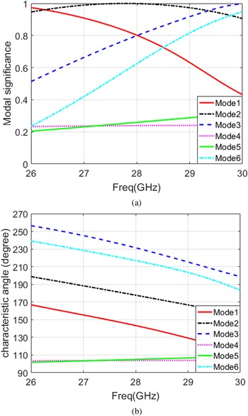
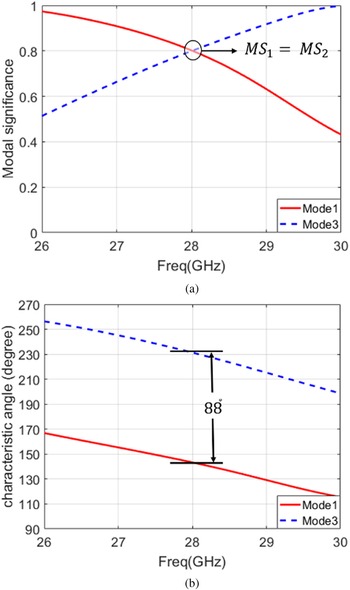
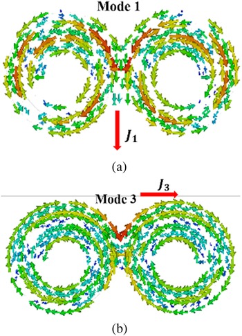
The CMA of the circular spiral-shaped MIMO patch antenna without feeding port is performed with the commercial simulator program CST MWS (ver. 2018) to provide a better explanation of the proposed antenna's performance. Initially, we will use the TCMs to understand how the circular polarization is obtained or what is the mechanism to get this type of polarization. As described in detail in the introduction part of this paper; the modal significance is the current mode normalized amplitude while the phase angle between a characteristic current and the corresponding characteristic field is physically described by the characteristic angle. The modal significance and characteristic angle are the most important two parameters, which effectively determine the radiation performance of each mode especially the circular polarization radiation that is generated from two modes. The two orthogonal modes are to be excited at 90° phase difference to produce effective CP radiation. As a consequence, the specifications for these two modes are: (a) the two modes of current distribution are diametrically orthogonal to one another, (b) the modal significances of the two orthogonal modes are identical (the normalized amplitudes of the two modes are the same), (c) the characteristic angles of these modes are β 1 = 135° and β 2 = 225°, i.e. 45° variance from the operating angle mode of 180°. It is worth pointing out that even though a single mode of characteristic angles of 135° or 225° (corresponds to λn = 1 or −1) has a poor efficiency of radiation because of a high stored reactive energy, the amalgamation of these two modes with the same characteristics as previously mentioned can still achieve a radiation efficiency of 100%. This is due to the additional inductive power in one mode compensates for the additional capacitive power in the other mode. Figure 12 displays the modal significance and characteristic angle of the first six modes. In all CMA results, J 1 to J 6 denote the 1st CM to 6th CM. It can be shown that in the desired impedance BW of interest (27.4–28.8 GHz), some MSs are >0.7, thus effectively exciting these modes. As shown in Fig. 13, mode 1 and mode 3 have the same magnitude and a phase difference of 88° at the operating frequency of 28 GHz. Although the phase difference between mode 1 and mode 3 is under 90 before feeding, circular polarization can successfully be achieved after feeding [Reference Yang, Liu and Gong28]. Figure 14 displays the modal current distribution of the mode 1 (J 1) and mode 3 (J 3) at the operating frequency of 28 GHz. It is evident that J 1 and J 3 are dominant at two perpendicular directions and equal in magnitude at broadside direction. Therefore, J 1 and J 3 are the orthogonal modes that are in control of circular polarization of the proposed circular spiral-shaped patch. It is very easy, through characteristics mode analysis, to determine the type of this circular polarization, whether it is right- or left-hand circular polarization (LHCP). The rotation's handedness is determined by the phase difference's sign. When rotated counterclockwise, the polarization state is left-handed with a phase shift of +90°. When rotated clockwise, the polarization state is right-handed with a phase shift of −90°. As it is clear from Fig. 10(b), the phase shift of mode 3 relative to mode 1 is close to +90, and therefore, we can say that this circular spiral MIMO patch antenna has a LHCP. For this reason, this spiral shape of patch was chosen to easily obtain circular polarization, unlike the traditional shapes as provided in the literature review.
Modal significance and characteristic angle of the first six modes.

Modal significance and characteristic angle of mode 1 and mode 3.

Modal current distribution. (a) Mode 1, (b) mode 3.

Characteristic mode analysis of the isolation enhancement
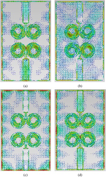
As we can see in Fig. 12, modes 1, 2, 3, and 6 contribute to the radiating BW in the desired impedance BW of interest, whereas modes 4 and 5 have no effect whatsoever. Moreover, based on the modal current distribution, we can observe that from Fig. 15, modes 1 and 3 do not contribute to the coupling between the two antennas as a result of the existence of current nulls, while modes 2 and 6 cause the coupling between the two antennas because of the high current density in the region between these two antennas, which in turn negatively affects the performance of this MIMO antenna system. According to our study, we can conclude that either mode 1 or 3 or a mixture of both are responsible for radiation.
Modal current distribution of the four contributing modes of the two-port MIMO antenna at 28 GHz, where (a) mode 1, (b) mode 2, (c) mode 3, (d) mode 6.

To improve isolation, we must tune the coupling modes (modes 2 and 6) out of the BW of interest, while also taking care to ensure that the double-faced LSMTM superstrate that will be added does not adversely damage the non-coupling modes (modes 1 and 3). The CMA was applied again to the circular spiral MIMO patch antenna loaded with LSMTM superstrate to ensure that the isolation improved. It can be seen from Fig. 16 that only modes 1 and 3 are available in the desired bandwidth range (27.4–28.8 GHz), while modes 2 and 6 are tuned out of the band of interest, and this confirms the improvement in isolation between the two ports of the MIMO antennas.
Characteristic angle of the first six modes with LSMTM superstrate.

Experimental verification
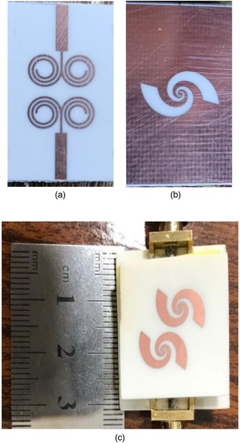
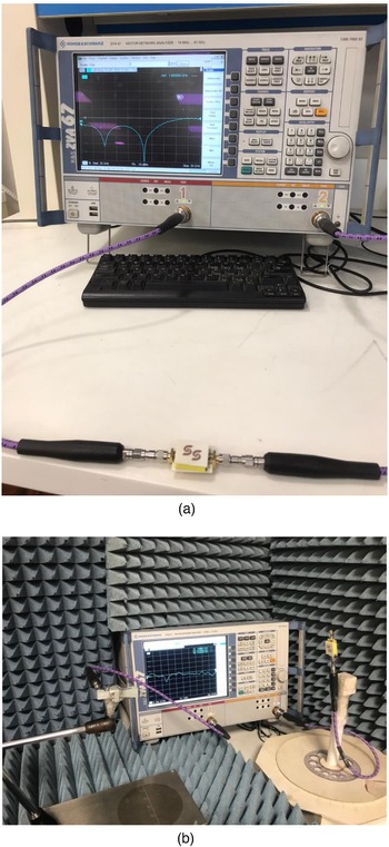
Finally, the prototype of the proposed circular spiral MIMO patch antenna loaded with LSMTM superstrate is developed, and the performance of this antenna is verified by using vector network analyzer R&S ZVA 67. The far-field measurement was accomplished utilizing the VNA in two-port measurement mode by measuring the transmission coefficient |S 21| between the antenna under test and the reference-standard gain horn antenna (LB-018400). The prototype of the proposed array is depicted in Fig. 17, and the measurement setups are shown in Fig. 18. The detailed discussion and comparative analysis of measured results are provided in the subsequent sections.
The prototype of the fabricated antenna. (a) Top view, (b) bottom view, (c) perspective view of the proposed antenna.

(a) S-parameters measurement setup, and (b) far-field measurement setup.

Reflection coefficients
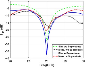
Figure 19 shows the simulated and measured reflection coefficients of the CP proposed circular spiral MIMO patch antenna. The reflection characteristics in Fig. 19 show that the antenna resonates at 28 GHz even after the novel double-face LSMTM is added as a superstrate indicating that the addition of this superstrate does not affect the radiating frequency of the antenna. As demonstrated in Fig. 19, the measured S 11 parameter indicates a good deal with the simulated one and has a bandwidth of 1.4 GHz (from 27.4 to 28.8 GHz).
Comparison between simulated and measured S 11-parameter results.

Transmission coefficients
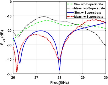
The mutual coupling between the MIMO elements can be expressed by the transmission coefficients. The measured and simulated transmission coefficients are plotted in Fig. 20. The transmission characteristics (S 21) in the operating frequency band show an improvement of about 32 dB (simulated) and 26 dB (measured) when using the LSMTM superstrate. This indicates the interaction between the antennas is minimized from −16 to −48 dB and from −14 to −40 dB for the simulated and measured results, respectively, which in turn indicates how much the isolation between the MIMO elements is improved due to incorporating the LSMTM superstrate.
Comparison between simulated and measured S 21-parameter results.

Envelope correlation coefficient
The envelope correlation coefficient (ECC) for any MIMO systems indicates the independence of one antenna from another in terms of its performance. Ideally, ECC should be 0 but <0.5 is also appropriate for actual cases. The following equation given in [Reference Abdelaziz and Hamad14] can be used to calculate the ECC:

where A 1(θ, φ) denotes the field pattern when antenna 1 is fed and antenna 2 is loaded by 50 Ω.
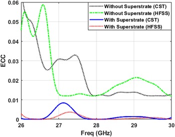
The simulated ECC values in both CST and HFSS software for the proposed MIMO antenna with and without LSMTM superstrate were <0.001 and <0.02, respectively, as shown in Fig. 21. The proposed antenna's ECC value is due to its low mutual coupling, which means that one element has less influence on the efficiency of the other element in the MIMO antenna.
The simulated envelope correlation coefficient (ECC) of the proposed MIMO antenna.

Diversity gain
Diversity gain (DG) is one of the main parameters for any MIMO antenna system, and it is defined as the loss in transmission power that occurs when the diversity scheme is used. Using the ECC of the MIMO antenna, the DG can be determined using the following relation [Reference Abdelaziz and Hamad14]:

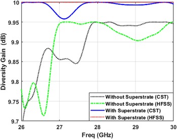
All of the antenna elements that have a DG with and without LSMTM superstrate are 9.99 and 9.95 dB, respectively, from both CST and HFSS software as investigated in Fig. 22, which is very similar to the optimum value of 10 dB.
The simulated diversity gain (DG) of the proposed MIMO antenna.

Channel capacity loss
Channel capacity loss (CCL) is one of the crucial characteristics in any MIMO antenna systems. CCL refers to the loss of channel capacity that can occur in the system as a result of correlation between the MIMO links. CCL can be determined using equation (14) as provided in [Reference Abdelaziz and Hamad14].

where $a = {\rm \;}\left[{\matrix{ {{\rm \sigma }_{11}} & {{\rm \sigma }_{12}} \cr {{\rm \sigma }_{21}} & {{\rm \sigma }_{22}} \cr } } \right]$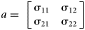 ,

and

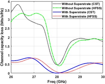
Figure 23 depicts the CCL for the proposed circular spiral MIMO antenna with and without LSMTM superstrate. It is plainly evident that the CCL value over the operating band is 0.5 bit/s/Hz for the MIMO antenna without superstrate while it is below the almost acceptable threshold of 0.4 bit/s/Hz for the loaded MIMO antenna with superstrate and this determines the high performance of the proposed system.
Channel capacity loss (CCL) of the proposed MIMO antenna.

Radiation patterns
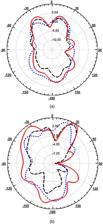
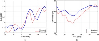
The radiation patterns with LHCP radiation were simulated and measured at the operating frequency of 28 GHz on two primary planes, E- and H-planes, or at ϕ = 0 and ϕ = 90, as illustrated in Fig. 24. It is noted in Figs 24(a) and 24(b) that a circular patch antenna without the double-face LSMTM superstrate has a radiation pattern with a main lobe direction at +17° (−17°), and has a half power beam width (HPBW) of 44.7° (44.7°) in the excitation of port 1 (port 2), and this causes a great coupling between the two circular patch antenna elements. After loading the proposed double-face LSMTM superstrate, the main direction of the radiation pattern is pointed to +29° (−29°) when port 1 (port 2) is excited, which proves that the mutual coupling between the two circular patch antenna elements has been almost suppressed, while the HPBW is reduced to 27.7° (27.7°), this shows improved directivity. The presence of this LSMTM superstrate makes the field distribution of the patch antenna more uniform, thus improving the overall gain of the proposed circular spiral MIMO patch antenna. The variation in the reflection phase is created by loading this LSMTM superstrate, which results in the phase delay of the radiated fields. The change in the direction of the radiation beam from 17° to 29° is produced due to the phase delay of the radiated fields. The simulated and measured radiation patterns agree fairly well. The simulated and measured gain and radiation efficiency are plotted in Fig. 25. The maximum simulated gain varies between 6.75 and 7.24 dB, while the maximum measured gain varies between 6.5 and 7 dB across the band of interest. The simulated radiation efficiency of the proposed antenna varies between 83 and 86%, while the measured radiation efficiency varies between 82 and 84% over the frequency band of interest.
Simulated and measured far-field radiation patterns of the proposed circular spiral MIMO patch antenna with and without the superstrate at 28 GHz. (a) E-plane. (b) H-plane.

Simulated and measured (a) gain, and (b) efficiency of the proposed MIMO antenna.

Comparison with state-of-the-art works
The proposed circular spiral MIMO patch antenna loaded with double-face LSMTM superstrate is compared to previously reported literary works, as indicated in Table 2. Table 2 concludes comparison in terms of substrate properties, gain, isolation, and other properties in order to establish distinctions between our results and those of other published designs. The proposed spiral MIMO antenna is observed to outperform the previous studies with regard to isolation. In addition, suggested MIMO antenna has a greater antenna gain than previously reported results [Reference Shoaib, Shoaib, Khattak, Shoaib, Chen and Perwaiz29–Reference Murthy33]. Despite this, the antenna arrays reported in [Reference Gupta, Briqech, Sebak and Denidni34–Reference Dey, Kiran and Dey36] outperformed the design proposed with regard to gain. However, they had a linear polarization and a smaller bandwidth, and they do not include MIMO performance study. In comparisons with other antennas discussed above, the presented antenna design shows better improving MIMO performance. As a result, the proposed MIMO antenna's suitability for 5G wireless communication devices is established.
Comparison of the proposed antenna's performance with state-of-the-art works.

Conclusion
This paper proposed a novel double-face LSMTM superstrate MIMO circular patch antenna. With the help of CMA, a systematic design approach is being presented. With established electromagnetic principles, this antenna has been designed and well understood. The TCMs were utilized to understand how the circular polarization is obtained and how the isolation of this design is improved. A good agreement between the simulation and measurement results has been noticed. The MIMO antenna has good diversity performance with high isolation between antenna elements (<48 dB), low ECC (0.001), CCL of 0.19 bits/s/Hz, and gain of 7.24 dBi, but it has high side lobe level (SLL) about −4.3 dB, and low front to back ratio (FTBR) about 6.4 dB due to the presence of LSMTM in the ground. The SLL can be reduced and FTBR can be improved further by the assist of the TCMs and it will be the future scope of this work. The proposed CP MIMO antenna may be a potential choice for 5G wireless communication systems due to its worthy performance characteristics.
 Ahmed Abdelaziz was born in Aswan, Egypt in 1992. He received the B.E. degree in Electronic and Communication Engineering from Arab Academy for Science, Technology and Maritime Transport, Egypt in 2014. He earned his Master degree in Electrical Engineering with thesis entitled “Design of Microstrip Antennas Using Metamaterials and Characteristics Mode Theory for 5G Wireless Communications” from the Faculty of Engineering, Aswan University in February 2019. He is currently working toward the Ph.D. degree in designing and optimizing MIMO antenna systems for 5G wireless communications at the Faculty of Engineering, Aswan University, Aswan, Egypt. Eng. Ahmed is working now as a Teaching/Research Assistant at the Higher Institute of Engineering & Technology, Luxor, Egypt. His current research interests include the antenna design, metamaterials, characteristic mode theory, and 5G.
 Hesham A. Mohamed received his B.Sc. degree in Electronics and Communication Engineering from the University of Menofia in 2003 and received his M.Sc. and Ph.D. degree from Ain Shams University in 2009 and 2014, respectively. He is currently an Associate Professor at Electronics Research Institute (ERI), Giza, Egypt. Dr. Hesham has Teaching Experience (more than 12 years' experience) as a lecturer in Electronic and Communication Engineering Department in the Faculty of Engineering Misr University for Science and Technology. Dr. Hesham is a SMIEEE senior member of the IEEE (Institute of Electrical and Electronic Engineers). He has authored or co-authored close to 30 journal papers, about 17 refereed conference papers, and attended and chaired several national and international conferences. He has supervised and co-supervised four Ph.D. and four M.Sc. theses at the Cairo University, Ain Shams University, Benha University, and Helwan University, the publications of my work in ranked international journals and conferences. He is a reviewer at international journals such as IEEE Microwave and Wireless Components Letters, IEEE ACCESS, Progress in Electromagnetics Research (PIER, PIER B, C, M, PIER Letters), Microwave and Optical Technology Letters, and International Journal of Circuit Theory and Applications. Dr. Hesham participates in more than six research projects at the national and international levels such as Egypt-NSF-USA joint fund program, Egypt STDF-France IRD joint fund program, and the European Committee programs of FP6 and FP7. His role is from C-PI to PI. He works as RF-Design Engineer (Antenna and Power Amplifier Module) (2018–2020) in the project “Small SAR Satellite antenna and transceiver system” and Communication Subsystem Engineering (2019–2020) in the project “Egyptian University Satellite (EUS-2)” RF-Design Engineer (2018–2019) in the project “Design of Radar Absorbing Materials (RAM) using Meta-materials” Wireless System Engineering, in the project (2015–2018), Development of High Data Rate X-Band Transmitter for LEO Remote Sensing Satellites, RF-Design Engineer (2015–2018) in the project “THE EGYPTION 2D RADAR” RF Design Engineer (2011–2014) in the project “Ultra-wideband Ground Penetrating Radar for Water Detection in Egypt” and RF-Design Engineer (2011–2014) February 2011–February 2014 “Novel Planar Antennas for the Most Recent Telecommunications Applications”. His research interests include microwave circuit designs, planar antenna systems, EBG structures, UWB components and antenna and RFID systems, radar absorbing materials, energy harvesting and wireless power transfer, smart antennas, microstrip antennas, microwave filters, metamaterials, and MIMO antennas and its applications in wireless communications.
 Ehab K. I. Hamad received the B.Sc. and M.Sc. degrees in Electrical Engineering from Assiut University, Assiut, Egypt in 1994 and 1999, respectively, and the Ph.D. degree in Electrical Engineering from Otto-von-Guericke Magdeburg University, Magdeburg, Germany in 2006. From 1996 to 2001, he was a Teaching/Research Assistant with the Aswan Faculty of Engineering, South Valley University, Aswan, Egypt. From July 2001 to December 2006, he was a Research Assistant with the Chair of Microwave and Communication Engineering, Otto-von-Guericke University Magdeburg. From July 2010 to April 2011, he was with the School of Computing and Engineering, University of Huddersfield, Huddersfield, UK as a Postdoctoral Research Assistant. He is currently a Full Professor for antenna engineering with the Department of Electrical Engineering, Faculty of Engineering, Aswan University, Aswan, Egypt. He has authored or coauthored over 60 technical peer-reviewed papers in international journals and conference proceedings. He is a supervisor on about 25 master and 13 Ph.D. theses in different universities in Egypt. His current research interests include antenna design, microstrip antennas, MIMO antennas, mm-wave antennas, multi-band/wide-band small antennas for 4G/5G, metamaterials, metasurfaces, UWB, RFID, RF energy harvesting, and implanted antennas for bio-medical applications. He is also interested in designing microstrip antennas using the theory of characteristic modes as well as designing antennas in the THz frequency band using graphene plasmonic material. Dr. Ehab has been a member of the Institute of Electrical and Electronics Engineers (IEEE) from 2004. He has been also a member of the Middle East Organization of Microwave, Antennas, and Propagation (MEOMAP) from March 2019. He is also a member of the Engineering Syndicate, Egypt from 1994. He received a best paper award. He is a Reviewer of many journals including IEEE Transactions on Antennas and Propagation, IET Microwaves, Antennas, and Propagations, Electronics, Electronic Letters, Radioengineering, PIERs, Journal of Electrical Engineering, Journal of Recent Advances in Electrical & Electronic Engineering, Microwave and Optical Technology Letters as well as many international conferences including EuCAP, National Radio Sciences, Asia-Pacific Microwave Conference, International Japan-Africa Conference on Electronics, Communications and Computations, and some others on Easy Chair and EDAS. He examined about 14 master theses and three doctoral dissertations in different universities in Egypt.