Nomenclature
- A
-
area of rotor disk (πR 2)
- C T
-
thrust coefficient (T/ρA(ΩR)2)
- C T, IGE
-
thrust coefficient of isolated rotor in the ground effect
- C T, OGE
-
thrust coefficient of isolated rotor out of the ground effect
- l c
-
horizontal distance from the corner line in the corner effect
- l v
-
horizontal distance from the vertex along the line equidistant from the two walls
- R
-
rotor radius
- T
-
thrust
- T OGE
-
thrust of isolated rotor out of the ground effect
- x
-
distance from the vertex along the x-axis
- y
-
distance from the vertex or corner along the y-axis
- z
-
distance from the ground plane along the z-axis
- z r
-
rotor height above the ground plane along the z-axis
-
 $\rho$
-
atmospheric density
-
$\varOmega$
-
rotational frequency of the rotor


1.0 Introduction
1.1 Background
Technical developments in miniaturising electronic devices have resulted in small electronic vertical take-off and landing (VTOL) unmanned aerial vehicles (UAVs). The 2010s witnessed rapid advancements in small multirotor UAVs, facilitating their usage in commercial applications and rescue operations. For instance, these UAVs have been utilised for pesticide spraying, film-making and delivering medicine to remote locations. In the 2020s, their application expanded to include the indoor exploration of hazardous areas and confined spaces unsuitable for human exploration. Enhancing the operational reliability of such indoor flights involves addressing several technical challenges: self-position detection in GPS-denied environments, and controlling rotor thrust in confined spaces affected by the reflection of rotor wake flow [Reference Shen, Michael and Kumar1]. From an aerodynamic perspective, interference between objects and rotor wake should be minimised to maintain consistent rotor thrust. Consequently, traditional VTOLs operate away from walls, with take-off and landing sites chosen in spacious areas. However, small multirotors designed for indoor use inevitably encounter interference between the rotor wake and nearby objects such as walls, which can alter rotor thrust and, in extreme cases, lead to crashes. To mitigate this risk, rapid thrust control or flight avoidance in areas where rotor thrust is liable to change is essential.
Quick thrust control technology has been developed for single-rotor helicopters using a variable pitch rotor, and multirotor control employing the same technology has also been implemented [Reference Cutler and How2]. However, most small multirotors regulate rotor thrust via rotation speed because this method reduces the number of mechanical components, thereby simplifying the flight control system and reducing both production costs and the weight of the UAV. When operating in indoor environments, the thrust of small multirotors can vary even when efforts are made to maintain a constant thrust, due to the current performance limitations of the devices. Aside from adopting variable pitch control to stabilise rotor thrust, it is crucial to avoid thrust alterations caused by wake flow interactions.
One approach to avoiding thrust changes involves strategic route planning that maintains a distance between multirotors and walls, ensuring that the rotor thrust remains effective. Therefore, understanding the impact of flow interactions between rotor wake and obstacles is vital for planning flight routes indoors.
1.2 Previous works
Rotor thrust changes in relation to walls, ceilings and side walls have been studied separately. These effects on a rotor are commonly referred to as proximity effects.
Concerning ground effect, thrust change was theoretically estimated by Betz in [Reference Betz3]. The phenomenon was later modelled by Cheeseman and Bennet [Reference Cheeseman and Bennett4]. As the rotor descends towards the ground plane, rotor thrust increases when the height above the ground (z r ) is less than approximately one rotor diameter. Additionally, flow visualisations of the rotor wake were conducted using particle image velocimetry (PIV) and the laser-light-sheet method for single rotors [Reference Lee, Leishman and Ramasamy5]. Since the 2010s, with the increased use of small multirotors, studies of ground effects on multiple rotors have been reported [Reference Mylapore and Schmitz6–Reference Otsuka, Kohno and Nagatani8]. For a quadrotor configuration, the rotor thrust near the ground plane can be lower than the hovering thrust out of the ground effect. Under the ground effect, the quadrotor’s wake generates a fountain flow at the centre of the quadrotor, creating a recirculation structure that penetrates the rotor, thereby reducing rotor thrust [Reference He and Leang7, Reference Otsuka, Kohno and Nagatani8].
For the ceiling effect, Rossow investigated the effects of both the ceiling and the ground planes on rotor thrust, both experimentally and theoretically, in 1985 [Reference Rossow9]. However, thrust change was scarcely investigated before 2013, as manned-scale helicopters rarely needed to fly close to ceilings. In 2013, Powers et al. reported the first experimental results on rotor thrust changes of a small quadrotor near a wall [Reference Powers, Mellinger, Kushleyev, Kothmann and Kumar10]. Conyers et al. observed that quadrotor thrust increases as the rotor ascends, provided the distance between the rotor plane and the ceiling plane is less than the rotor diameter [Reference Conyers, Rutherford and Valavanis11]. Sanchez-Cuevas et al. measured rotor thrust under the ceiling effect and attempted to model the effect to operate a quadrotor for bridge inspection [Reference Sanchez-Cuevas, Heredia and Ollero12]. Hsiao and Chirarattananon created a model for the ceiling effect using the blade element momentum theory and validated the model based on experiments using a small quadrotor [Reference Hsiao and Chirarattananon13]. Furthermore, numerical analyses on the ceiling effect on small quadrotors were conducted [Reference Jimenez-Cano, Sanchez-Cuevas, Grau, Ollero and Heredia14, Reference Robinson, Chung and Ryan15], with Nishibe et al. clarifying the flow field using the PIV method [Reference Nishibe, Koizumi and Sekiguchi16].
For the side wall effect, thrust changes have been minimally investigated compared to ground and ceiling effects, as both manned helicopters and small multirotors typically avoid flying near walls to prevent rotor damage. Adapting the rotor covers of small multirotors has allowed them to fly closer to side walls, increasing the need to investigate thrust requirements for applications such as building wall inspections. Tanabe et al. conducted a numerical investigation of the flow field on a small quadrotor hovering near a wall, noting that a decrease in thrust at wall-near side rotors can cause the multirotor to glide towards the sidewall [Reference Tanabe, Sugiura, Aoyama, Sugawara and Yonezawa17]. Carter et al. summarised the effects of ground, ceiling and side walls [Reference Carter, Bouchard and Quinn18]. They conducted PIV and thrust measurements using a micro quadrotor, which showed that the sidewall effect decreases rotor thrust by approximately 3% when the rotor is close to the wall. Ding et al. enhanced the wall effect on rotors using ducts and applied it to estimate the distance between a small quadrotor and a side wall with sensor fusion of a range finder and an optical flow sensor [Reference Ding, Bai, Dong and Chirarattananon19].
To study the combination of object proximity effects, Carter et al. investigated thrust and visualised the rotor wake of a quadrotor experiencing the corner effect [Reference Carter, Atte and Rauleder20]. The corner effect is a combination of the ground and side wall effects. Zagaglia et al. presented PIV results showing rotor wake behaviour in the corner effect near a cube object and changes in thrust as the rotor approached a side wall horizontally [Reference Zagaglia, Giuni and Green21]. Both this study [Reference Zagaglia, Giuni and Green21] and another [Reference Pickles, Green and Giuni22] indicated the formation of recirculation flow in the corner effect near a cube.
1.3 Proposal
Although the effects of proximity to walls, ceilings and the ground have been investigated individually, there are only a few studies that have explored the combined influences on rotor thrust. As depicted in Fig. 1, indoor environments typically include corners and vertices, not merely flat surfaces such as ground planes, side walls and ceilings. A corner consists of a wall and a plane, while a vertex is formed by two side walls and a plane. Multirotors may need to approach the ceiling, side wall, ground plane, corner or vertex to fulfil the objectives of indoor flight. Near the corners or vertices of a room, changes in rotor thrust are expected due to complex airflow dynamics. In this study, we refer to the impact of vertices and corners on rotor thrust as vertex effect and corner effect, respectively. Although a few studies have focused on rotor thrust near corners [Reference Prothin, Fernandez Escudero, Doué and Jardin23], the implications of these effects remain unclear.
Schematic of an indoor environment.

Previous research on ground effect established that, under certain conditions, the generation of fountain flows and the formation of recirculation flows between the fountain flow and rotor result in a thrust decrease near the ground for quadrotors [Reference Otsuka, Kohno and Nagatani8]. A similar effect occurs when the rotor is near a vertex formed by two walls and a ground plane or a corner formed by one wall and a ground plane. Computational fluid dynamics analyses indicate that vertices create fountain flows, inducing recirculation flow structures [Reference Otsuka, Hara, Tokutake and Nagai24], which suggest a decrease in rotor thrust near vertex structures compared to isolated rotor thrust.
Understanding these corner and vertex effects is crucial for deploying small VTOLs in indoor exploration, as it helps in avoiding thrust reduction in confined spaces. Knowing how thrust changes relative to the rotor’s position near a vertex and a corner allows operators of small VTOLs to plan flight trajectories that avoid areas where thrust decreases, thereby minimising the risk of crashes and collisions during indoor exploration.
1.4 Objective
The aim of this study is to assess how the corner and vertex effects impact rotor thrust. The study analysed the relationship between rotor position and thrust through thrust measurements. Additionally, the study visualised the structure of the rotor wake in the vertex effect using the laser light sheet method to clarify the mechanism of thrust change. Clarifying the dynamics of rotor thrust change due to the vertex effect can reduce the risk of flight failures during indoor explorations. Vertex structures consist of two walls and either a ground plane or a ceiling. This study focuses on the corner and vertex effects on the ground side, as thrust losses near the ground are more likely to result in collision accidents compared to those near the ceiling.
The remainder of this paper is organised as follows: Section 2 describes the measurement results of rotor thrust in the corner and vertex effects; Section 3 presents the visualisation of rotor wake; Section 4 concludes the study.
2.0 Experimental method
Rotor thrust changes caused by the corner and vertex effects were evaluated by altering the rotor’s position relative to the corner or vertex. Furthermore, flow visualisation and hot-wire velocimetry were performed.
2.1 Experimental system
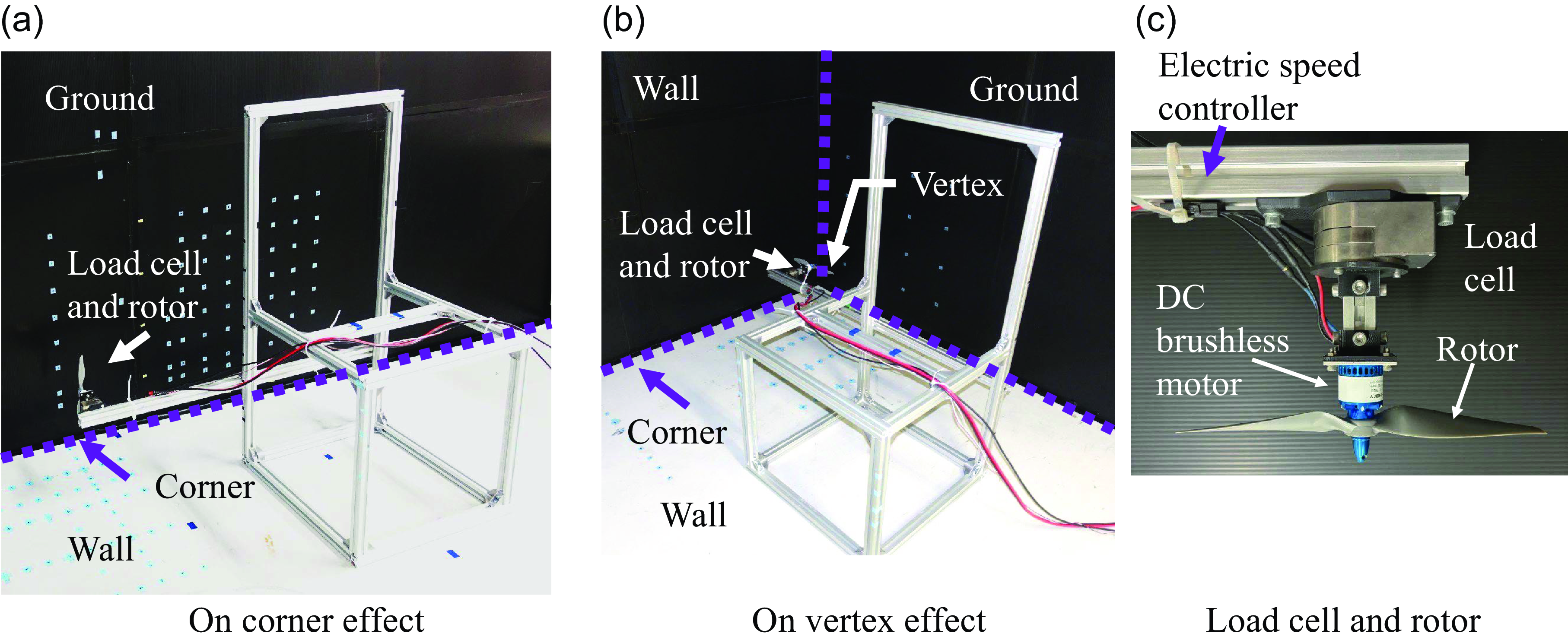
Figure 2 illustrates the setup of the experimental system and the walls forming the corner and vertex. The walls were constructed from black plastic boards to facilitate flow visualisation using the laser light sheet method. Figure 2(a) depicts a wall configuration for the corner effect, and Fig. 2(b) shows the setup for the vertex effect. The side lengths of the walls were 990mm, which is 4.3 times the rotor diameter.
Setup of the experimental stand in corner and vertex effect situations.

In vertex situations, plastic board walls were used as both walls and ground planes, enabling the test stand to be moved horizontally in alignment with the room floor. The stand’s position was set using a scale with an accuracy of 1mm.
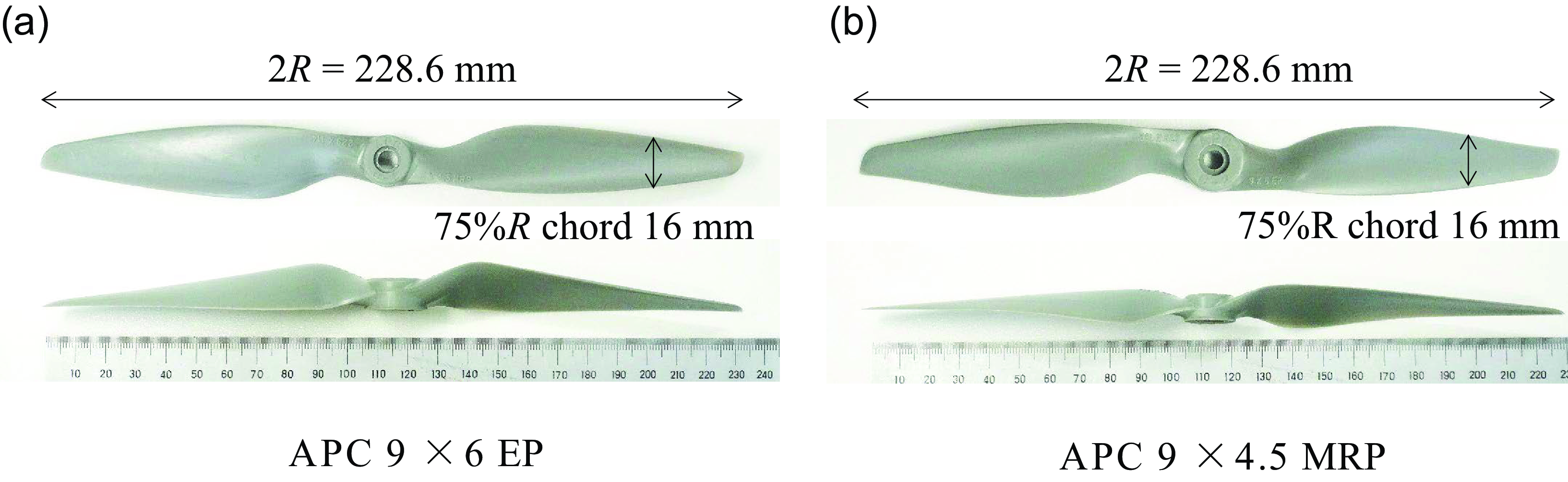
The rotor used in the experiment, an APC 9×6 EP made of glass fibre, has a diameter of 228.6mm. It was driven by an electronic brushless motor, with the rotation speed controlled by an electric speed controller featuring closed-loop speed control. This setup maintained the rotation speed within 10rpm of the set speed. The chord at 75% of the rotor radius (R) is 16mm, as shown in Fig. 3. Additionally, an APC 9×4.5 MRP rotor was used to evaluate the effect of a different thrust coefficient (C T ) with a smaller blade pitching angle compared to the APC 9×6 EP. The thrust coefficient is defined as follows:
 \begin{align}{C_T} = \;T/\rho A{\left( {\Omega R} \right)^2}, \end{align}
APC 9×6 EP and APC 9×4.5 MRP rotors.

where T is the rotor thrust,
 $\rho$
is the atmospheric density, A is the area of the rotor disk,
 $\varOmega$
is the rotor revolution frequency, and R is the rotor radius. The chord at 75% rotor radius of the APC 9×4.5 MRP is 16mm. The thrust coefficients out of the ground effect (C
T, OGE
) of the rotors are 1.62×10⁻² for APC 9×6 EP and 1.34×10⁻² for APC 9×4.5 MRP at 6,000rpm. C
T, OGE
was measured with z
r
maintained above 5.0R, and the rotor thrust direction was reversed relative to the ground plane. Furthermore, C
T
was used to account for the variations in atmospheric density across the experimental results.
2.1.1 Thrust measurement
The rotor and load cell were mounted on the test stand, as depicted in Fig. 2(c). The load cell, a Leptrino SFS055YA500U6, has a resolution for a z-axis force of 5.0 × 10⁻³N. The sensor’s output was calibrated against a standard weight. The standard deviation of the C
T, OGE
of the APC 9×6 EP at 6,000rpm was 0.09% of C
T, OGE
. The room temperature during the experiment was maintained between 22 and 26°C to minimise changes in
 $\rho$
.
2.1.2 Flow visualisation
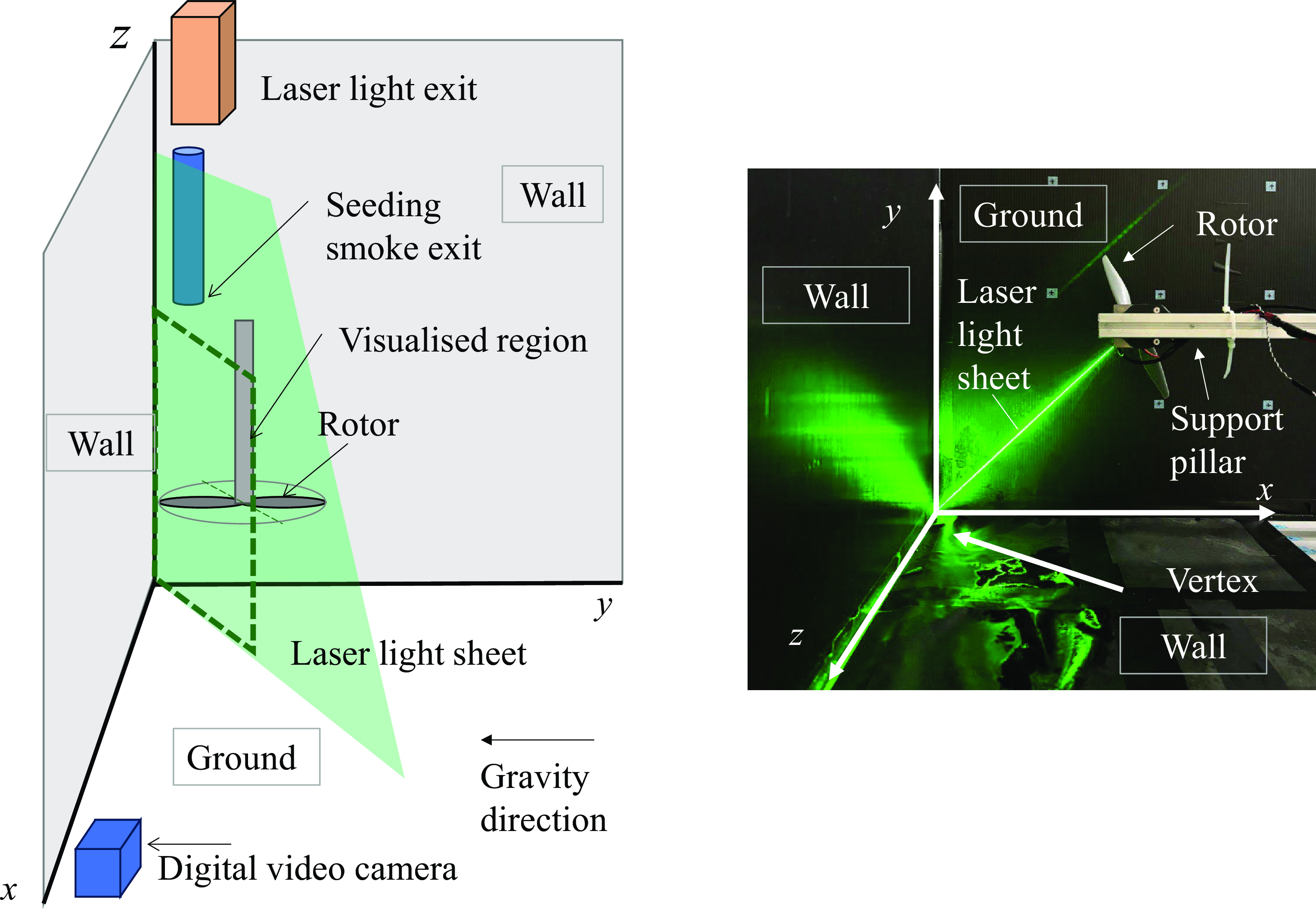
The wake of the rotor in the corner or vertex effects was visualised using the laser light sheet method. The visualised plane included the vertex points and rotor axis. The target visualisation region is the flow field between the rotor and walls. The laser light sheet source was a diode-pumped solid-state 532nm green laser (MGL-N-532, Changchun New Industries Optoelectronics Technology), with an output of 3W at the exit of the light source via an optical fibre cable. The setup of the flow visualisation and coordinate system are shown in Fig. 4. Seed particles were introduced from the ground plane side using a smoke generator (Dainichi, PS-2107), with the seeding material being propylene glycol liquid. The diameter of the seeding particles was 10μm. The visualised plane was recorded by a video camera (Sony, FDR-AX700) at a frame rate of 960fps. In the visualisation of the rotor wake in the corner effect, a laser sheet was inserted from different directions, ensuring the sheet was perpendicular to the corner line. The positions of the wall and ground in Fig. 2(a) were swapped.
Setup for rotor wake flow visualisation using the laser light sheet method.

2.1.3 Hot-wire velocimetry
Wake velocity was measured using the hot-wire velocimetry method. The system used was a Smart KANOMAX, CTA 7250. The hot-wire probe, an X-shape made of tungsten wire, was calibrated from 4.0 to 14.0m/s in a blown-down type open-return low-speed wind tunnel with a 0.3 × 0.3m square test section.
2.2 Conditions
2.2.1 Thrust measurements
Thrust measurements were conducted to assess both the corner and vertex effects. These measurements were conducted three times under set conditions to evaluate the accuracy of the measurements.
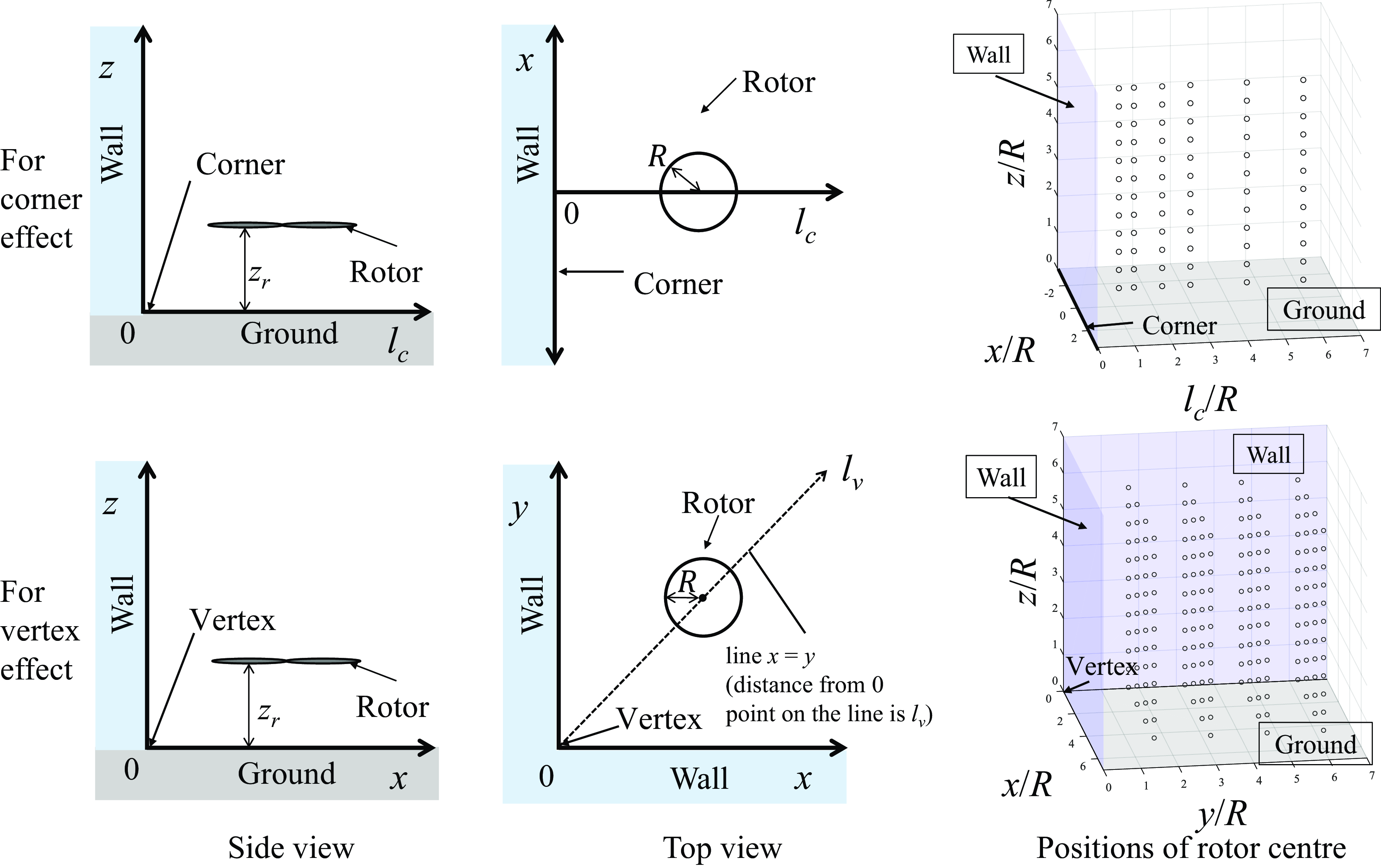
In the scenario involving the corner effect, the horizontal distance from the corner line (l c ) was adjusted from 1.1 to 6.0R. z r was varied from 0.5 to 6.0R.
For the vertex effect, the horizontal distances from the vertex point along the x and y axes were altered from 1.5 to 6.0R. Additionally, the horizontal distance from vertex points along the line where x equals y (l v ) was used to evaluate the vertex effect.
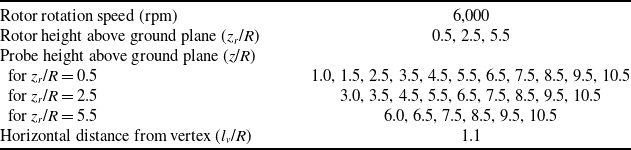
Regarding variations in z r from 0.5 to 6.0R for the vertex effect, the thrust was evaluated at 4 × 4 grid points on the x–y plane. Moreover, thrust changes in horizontal planes at z r /R = 0.5, 2.5, and 5.5 were examined across 7 × 7 grid points on the x–y plane at shorter intervals to increase the resolution of the thrust change map in these planes. Thrust was expressed as the ratio of C T to C T, OGE of the isolated rotor.
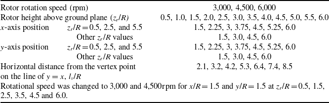
The rotor speed for the basic experimental condition was set at 6,000rpm, which was set to lift a 1.6kg quadrotor in a hovering state. To investigate the effect of Reynolds number dependency, the speed was adjusted to 3,000 and 4,500rpm for specific cases. The Reynolds numbers at 75% of the rotor radius were 2.83 × 10⁴, 4.24 × 10⁴, and 5.65 × 10⁴ for 3,000, 4,500, and 6,000 rpm, respectively. The respective Mach numbers at the blade tip were 0.10, 0.16 and 0.21.
The conditions of the thrust measurements for the corner and vertex effects are detailed in Tables 1 and 2, respectively. Parameters for both scenarios are illustrated in Fig. 5.
Thrust measurement conditions in corner effect

Thrust measurement conditions in vertex effect

Position parameters of rotor near the corner and vertex.

2.2.2 Flow visualisation and hot-wire velocimetry
Tables 3 and 4 list the conditions for flow visualisation using the laser light sheet method, and Table 5 specifies the conditions for measuring fountain flow velocity in the vertical direction with hot-wire velocimetry in the vertex effect. To prevent collisions between the hot-wire probe and the rotor blade tip, velocity measurements were not taken near the blade tip. Table 6 specifies the conditions for measuring fountain flow velocity in the horizontal direction. The velocity was measured three times for each condition.
Flow visualisation conditions in corner effect

Flow visualisation conditions in vertex effect

Hot-wire velocimetry conditions in vertical direction for fountain flow in vertex effect

Hot-wire velocimetry conditions in horizontal direction for fountain flow in vertex effect

2.3 Accuracy
Thrust measurement data can fluctuate due to inaccuracies in rotor positioning using scales, sensor noise from rotor vibration, and changes in room temperature. To address these potential errors consistently, a 95% confidence interval, which is 1.96 times the standard deviation, is provided for each scenario based on data measured three times. To enable easy comparison of thrust changes among data measured under different conditions, the data were transformed into dimensionless variables.
For hot-wire velocimetry, 1.96 times the standard deviation of the averaged flow velocity, based on three measurements, is represented using error bars in the results.
3.0 Results and discussion
3.1 Corner effect on rotor thrust
Figure 6(a) illustrates the change in rotor thrust due to the corner effect, varying with z
r
. Figure 6(b) shows the thrust change as a function of l
c
at different z
r
, which is extracted from Fig. 6(a). In Fig. 6(a), the curve with solid circles shows measured isolated rotor thrust in the ground effect without a side wall. Within the experimental range of l
c
/R from 1.1 to 6.0, rotor thrust monotonically increases as z
r
decreases, except for fluctuation within the sensor noise in Fig. 6(a). The thrust is smaller than the model proposed by Cheeseman and Bennett [Reference Cheeseman and Bennett4] for z
r
/R below 2.0. In Fig. 6(b), for thrust changes with respect to l
c
at the same z
r
significant differences in thrust are not observed at l
c
 $\geqq$
3R conditions. At l
c
< 3R and z
r
/R = 1.5 and 2.0, C
T
/C
T, OGE
decreases as l
c
decreases. For z
r
/R = 1.5, C
T
decreases from 104% to 102% of C
T, OGE
. For z
r
/R = 2.0, C
T
decreases from 102% to 101% of C
T, OGE
. In the experiment, the thrust in the corner effect is consistently greater than one, aside from fluctuations due to sensor noise.
Thrust change with variation of z r and l c in the corner effect.

A corner comprises one side wall and one ground plane. Initially, it was anticipated that the thrust would increase more than observed in the ground effect alone because the side wall can impede rotor wake spreading. However, the observed thrust change in the corner effect, with variations in z r , was similar to that of the thrust coefficient in the ground effect (C T, IGE ). The C T in the corner effect was greater than C T, IGE by a margin less than 2% at the same z r .
For thrust changes due to variations in the distance between the rotor and side wall at a constant rotor height, the experimental results do not show a significant difference in thrust between the corner and ground effects. Therefore, our experimental results demonstrate that a horizontal approach towards the side wall in the corner effect yields a thrust change of within 2% for a single rotor.
This result differs from the observations in a previous study [Reference Zagaglia, Giuni and Green21], with a thrust reduction of over 5% due to the corner effect when reducing l c /R from 3 to 2, in the presence of a cube’s side wall.
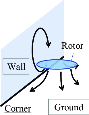
The observed difference in thrust could be attributed to the difference in height of the side wall. Previous studies using PIV with a low cube side wall have reported the formation of recirculation flow structures near the ground plane [Reference Zagaglia, Giuni and Green21, Reference Pickles, Green and Giuni22]. We anticipate that similar structures as in our experiment will appear in the corner effect with a high side wall, as depicted in Fig. 7. The height of the side wall can change the strength of the recirculation and vary the rotor thrust under the corner effect when the rotor is at the same position relative to the corner.
Sketch of wake flow structure in the corner effect.

However, the thrust measurements observed in our study could not confirm the presence of the recirculation structure. The existence of the recirculation structure in the corner effect is discussed in Section 4, based on flow visualisation experiments. The impact of side wall height on thrust change remains unclear in the current study. Furthermore, the thrust variation in the corner effect for multiple rotors, such as multirotors, remains unexplored.
3.2 Vertex effect on rotor thrust
Figure 8 shows the changes in C T at four points within the vertex effect. The solid black line represents the C T variation of a single rotor IGE. Point A (x/R = 1.5, y/R = 1.5) is located near the vertex, while Points B (x/R = 1.5, y/R = 3.0) and B’ (x/R = 3.0, y/R = 1.5) are farther from one wall compared to Point A. The two points are different in rotor moving direction to the vertex at the nearest wall side. The rotor blade near the wall moves to the vertex at point B, and subsequently moves opposite to the vertex at point B’. Point C (x/R = 6.0, y/R = 6.0) is positioned far from the vertex. At Point C, C T increases as z r decreases, except for a minor increase due to accuracy fluctuations between 6.0 and 3.0R. At Point A, the thrust change reaches a local minimum at z r /R = 2.5, where C T /C T, OGE = 0.93. Similarly, at Point B, the thrust change shows a local minimum at z r /R = 2.5, with C T /C T, OGE = 0.96. For Point B’, the thrust change also reaches a local minimum at z r /R = 2.5, where C T /C T, OGE = 0.97, which is 1% higher than at Point B.
Thrust change with variation of z r in the vertex effect.

The characteristics of thrust change at Points A and B differ from those in the ground effect, and the trend is similar to that of quadrotor thrust in the ground effect in terms of the appearance of a local minimum thrust point. The local minimum thrust increases by increasing the distance from one side wall from Point A to Point B.
Comparing points B and B’, the local minimum C T /C T, OGE at Point B is 1% lower than at Point B’. The z r at the local minimum thrust is the same for both points. The impact of the rotation direction on the thrust changes is not significant owing to the difference in thrust between the two positions being negligible compared to the sensor accuracy.
Figure 9 shows a contour map of C T /C T, OGE across three horizontal planes at z r /R = 0.5, 2.5, and 5.5. These heights correspond to the heights of thrust in the vertex effect near the ground plane, thrust at the local minimum, and thrust outside of the vertex influence. Conditions for measured positions in the x and y directions were changed by 0.75R for the map at z r /R = 2.5 to identify the region of thrust decrease at the minimum thrust. At z r /R = 0.5, C T /C T, OGE in the plane is generally around 1.08. At z r /R = 2.5, C T /C T, OGE in regions far from the side wall is approximately 1.0. Near the side wall, C T /C T, OGE shows values less than one. The minimum C T /C T, OGE in the region near the vertex is 0.93, differing from single rotor thrust in IGE, where C T /C T, OGE is greater than one. At z r /R = 5.5, C T /C T, OGE is approximately 1.00, and fluctuates within the accuracy deviation, indicating that the significant thrust change caused by the vertex is not observed at this height.
Contour map of C T /C T,OGE in three horizontal planes at the heights of z r /R = 0.5, 2.5 and 5.5.

Figure 10 presents three-dimensional isosurfaces of C T /C T, OGE at values of 0.92, 0.94, 0.96, 0.98, 1.02, 1.04, and 1.06 to visualise the thrust change in the vertex effect. These isosurfaces are generated from a grid of 4 × 4 × 12 measured points. The isosurfaces are linearly interpolated. The sources of thrust data and isosurface visualisation files are shown in Files 1 and 2, respectively. Values of C T /C T, OGE below 0.98 are observed near the vertex at z r /R from 1.5 to 4.5. The minimum C T /C T, OGE under the measured conditions is 0.92, occurring at x/R = 1.5, y/R = 1.5 and z r /R = 2.5.
Three-dimensional isosurface of thrust in vertex effect relative to thrust out of vertex effect.

When the rotor is 5.0R away from one of the side walls above or more than 5.0R from the ground plane, the thrust decrease caused by the vertex effect is negligible, as shown in Figs 8, 9 and 10, where C T /C T, OGE is greater than 0.98. Therefore, for indoor flight path planning, a small multirotor can avoid thrust changes due to the vertex effect by maintaining a distance greater than 5.0R from walls or keeping z r /R above 5.0. Under z r /R = 5.0, a region of C T /C T, OGE below 0.98 exists near the vertex in the specific conditions of rotor position. Figure 11 illustrates thrust changes at z r /R = 0.5, 2.5, and 5.5 on the plane where x is equal to y. C T /C T, OGE is below 0.98 at l v /R = 2.1 and z r /R = 2.5, conditions under which the vertex effect appears.
Thrust in vertex effect relative to isolated rotor thrust for conditions where x equals y at three different z r levels.

It is considered that the occurrence of C T /C T, OGE values below one is caused by flow recirculation between the wake around the vertex and the rotor, as depicted in Fig. 12. This recirculation increases the local inflow ratio on a part of the rotor plane, resulting in a decrease in thrust. It is notable that C T /C T, OGE appears to depend on both the recirculation near the vertex and the ground effect. The recirculation decreases thrust while the ground effect increases it. Therefore, C T /C T, OGE is greater than one at lower z r near the vertex, where the ground effect exceeds the thrust decrease caused by the recirculation flow.
Sketch of wake flow structure in the corner effect.

A similar thrust decrease caused by recirculation is observed in the ground effect for small quadrotors [Reference Otsuka, Kohno and Nagatani8]. However, the wake structure cannot be discerned from the thrust measurements alone. The mechanism of thrust decrease in the vertex effect remains unclear and is further discussed in Section 4, based on the results from flow visualisation.
3.3 Effect of thrust coefficient and Reynolds number
To understand the dependency of the vertex effect on C T and Reynolds number, the thrust in the vertex effect was evaluated by varying rotor rotation speed and rotor shape, which results in different thrust coefficients.
Figure 13(a) shows the rotor thrust in the vertex effect as the rotor speed varies. Figure 13(b) shows the rotor thrust in the vertex effect with two rotors identical in rotor radius and Reynolds number. By altering the rotor rotation speed in Fig. 13(a), the Reynolds number changed from 2.83 × 10⁴ (3,000rpm) to 5.65 × 10⁴ (6,000rpm) at almost the same C T of 1.62×10⁻². In the three rotor rotation speed conditions at x/R and y/R = 1.5, no significant difference in C T /C T, OGE with variation in height is observed. These results indicate that the effect of Reynolds number is negligible within the experimental range of Reynolds numbers.
Thrust change in the vertex effect with variation of rotor rotation speed and rotor loading.

For the two rotors with C T, OGE = 1.62×10⁻² and 1.25×10⁻², thrust change with variation in z r is approximately the same in Fig. 13(b). The minimum C T /C T, OGE for APC 9×6 EP is higher than that for APC 9×4.5 MRP by within 1%. The thrust difference between the two rotors falls within the 95% confidence interval. These findings suggest that differences in rotor loading have a minimal impact on thrust change in the vertex effect in this experiment. To generalise the thrust change with variation of z r for rotors of various shapes and blade pitch angles, further investigation is required.
3.4 Rotor wake visualisation and hot-wire velocimetry
The wake of the rotor in the corner and vertex effects was visualised using the laser sheet method to elucidate the flow structure within the vertex effect. Additionally, hot-wire velocimetry measurements were undertaken to assess the differences in wake flow velocity in the vertex effect.
3.4.1 Flow visualisation in the corner effect
Figure 14 shows the visualised flow around the rotor in the corner effect at z r /R = 2.0 and l c /R = 1.5. There is a recirculation flow between the rotor wake and the side wall, as noted in previous studies [Reference Zagaglia, Giuni and Green21, Reference Pickles, Green and Giuni22]. The visualised wake support occurrence of recirculation flow as illustrated in Fig. 7. In the visualisation, the fountain flow along the side wall is partially deflected towards the rotor at z/R = 2.0, while a portion of the fountain flow moves upward along the side wall above z/R = 2.0. The PIV results by Zagaglia et al. showed that most of the fountain flow was deflected at this height [Reference Pickles, Green and Giuni22]. The difference in the amount of flow detached from the side wall is assumed to be due to the variation in sidewall height. Although the quantity of detached flow cannot be quantified from the visualisation alone, it is observed that the longer side wall directs more fountain flow along the wall compared to a side wall of the cube with a height of 2R. A reduction in the deflection of fountain flow could weaken recirculation and reduce the magnitude of thrust change when approaching the side wall at a constant height. To fully understand the effect of side wall height on thrust change, further investigation is needed.
Visualised wake of the rotor in the corner effect at the height of rotor diameter.

3.4.2 Flow visualisation in the vertex effect
Figure 15(a) shows the visualised flow around the rotor near the vertex at z r /R = 0.5, 2.5, and 5.5. Video of the visualised flow is shown in Movie 1. The right side of Fig. 15(a) illustrates a sketch of the rotor wake structure. The visualisation laser sheet at z r /R = 0.5 is canted a few degrees and is not parallel to the vertical corner line; however, this canting is considered negligible for understanding the rotor wake structure. Figure 15(b) shows selected frames at z r /R = 2.5 and 5.5 with the same time interval.
Visualised wake of the rotor in the vertex effect at three different rotor heights above the ground.

At z r /R = 0.5, the wake flow moving towards the vertex side soars along the wall, passing through the space between the blade tip and the walls. The video captured black small circles soaring at the edge of the fountain flow; these circles represent voids in the seeding mist caused by blade-tip vortices. The soared flow spreads while moving upward.
At z r /R = 2.5, a recirculation structure is observed between the fountain flow and rotor wake, which supports occurrence of the wake structure illustrated in Fig. 12. The width of the fountain flow after passing the rotor narrows compared to that at z r /R = 0.5. It is noted that the wake flow near the ground plane is slower and more unstable than in the other two height conditions, as seen in the recorded video.
At z r /R = 5.5, the flow recirculation structure between the rotor and the fountain flow is evident. However, Fig. 15(b) and Movie 1 show that the velocity of the fountain flow is slower than that at z r /R = 2.5. The fountain flow velocity will be discussed further in Section 3.4.3. The flow that penetrates the clearance between the rotor blade tip and the corner struggles to move along the corner above the rotor plane height. Most of the fountain flow forms a recirculation structure from the ground plane to rotor height, implying that the upstream flow passing the rotor has not contracted. The video showed that small black voids caused by blade-tip vortices move along the rotor wake edge. Outside the recirculation area, the flow moves in the direction opposite to the vertex. Thus, it is expected that the strongest recirculation structure forms when z r /R is approximately 2.5.
Previous studies on quadrotor wake have confirmed that a recirculation structure around a rotor causes a thrust decrease and a central recirculation structure in quadrotor results in a thrust reduction in the ground effect. Consequently, the formation of a circulation structure between the fountain flow and rotor wake appears to decrease rotor thrust in the vertex effect.
The visualised wake structure supports this mechanism. Furthermore, the lowest rotor thrust of C T /C T, OGE = 93% was recorded at z r /R = 2.5. Both experimental results substantiate the proposed mechanism. However, the difference in fountain flow velocity was unclear from the video using the laser sheet method alone. To accurately evaluate the velocity differences of the fountain flow at varying heights, hot-wire velocimetry was conducted on the wake in the vertex effect.
3.4.3 Hot-wire velocimetry in the vertex effect
Figure 16 shows the averaged vertical flow velocity measured by hot-wire velocimetry. The fastest vertical velocity at each z r condition decreases as z r increases. For z r /R = 0.5, 2.5 and 5.5, the fastest velocity near the wall is recorded at z/R = 1.5. Under the conditions of z r /R =2.5 or 5.5, the fastest vertical velocity is observed at the position closest to the corner with the variation of l v . Although the fastest vertical velocity at z r /R = 0.5 is recorded at l v /R = 0.42 and z/R= 1.5, the second and third fastest velocities at the same z are recorded at the two closer points, l v /R = 0.14 and 0.28. Thus, the vertical velocity near the corner exhibits characteristics of fountain flow.
Vertical velocity of fountain flow measured using hot wire with variation of rotor height z r .

The vertical velocity closest to the corner, varying with z and z r , is shown in Fig. 17. Conditions where z equals z r are marked with filled symbols. The fountain flow exhibits the fastest velocity at z/R = 1.5 or 2.5 across the three z r conditions, suggesting that z of the fastest flow seems to be independent of z r . The velocity at z/R = 1.5 decreases as z r increases, supporting the observed deceleration of fountain flow velocity with increasing z r as seen in flow visualisation.
Vertical velocity of fountain flow measured using hot-wire velocimetry in the vertex effect with variation of probe height z. Filled symbols indicate that the rotor height equals the measured height. The rotor is at l v /R = 2.1 and z r /R = 0.5, 2.5, and 5.5.

Figure 18 shows the averaged horizontal velocity of fountain flow at l v /R = 1.1 and z/R from 0.5 to 7.5 at z r /R = 0.5, 2.5, and 5.5, with error bars indicating a 95% confidence interval. The horizontal position in l v was adjusted to observe the horizontal flow of the fountain near the blade tip in the vertical position variation. For z r /R = 0.5, horizontal velocity ranges from 2.0 to 4.0m/s. For z r /R = 2.5, the fastest horizontal velocity is 6.5m/s at 0.5R above the rotor. The velocity decreases as z increases. For z r /R = 5.5, the fastest horizontal velocity is 5.0m/s at z/R = 3.0, which is a height 0.5R above the rotor. In the condition of z r /R = 0.5, although fountain flow gradually expands outward, the volume of flow returning to the rotor is not significant. At z r /R = 2.5 and 5.5, a peak in horizontal velocity is observed near the rotor height. The horizontal velocity trend indicates that recirculating flow is formed at the two rotor height conditions. The fastest horizontal velocity at z r /R = 2.5 is faster than that at z r /R = 5.5. Thus, it is expected that the recirculating flow at z r /R = 2.5 is the strongest among the three z r conditions.
Horizontal velocity of fountain flow measured using hot-wire velocimetry in the vertex effect.

From the flow visualisation and hot-wire velocimetry, we confirmed the formation of a recirculation structure between the wake on the corner side and the rotor blade tip in the vertex effect above z r /R = 1.5. Furthermore, the fountain flow velocity, which is part of the circulation, decreased as z r /R increased. The experimental results indicated that recirculation became significant at z r /R = 2.5 as a result of the decrease in vertical fountain flow velocity with increasing z r and the increase in horizontal velocity directing the fountain flow toward the rotor. The balance of these two factors appears to result in the local minimum thrust near the vertex at z r /R = 2.5.
Although the experiments demonstrated thrust changes in the vertex effect and their mechanisms for decreasing the rotor thrust of a small rotor, the Reynolds number is limited for small VTOLs. To apply the thrust change estimation for manned-scale VTOLs, additional investigation using a manned scale model is required. Furthermore, the study focused on the vertex effect and corner effect of a single small rotor. Thrust changes in small multirotors can differ because multiple rotors involve wake flow interaction, and rotor thrust depends on the rotor wake structures. From the perspective of understanding the vertex effect and corner effect, studies on the ceiling side are also necessary.
4.0 Conclusions
Rotor thrusts in the corner and vertex effects on the ground side were evaluated by altering the rotor’s position relative to side walls and the ground plane to determine the changes in thrust within these effects for flight area planning in indoor environments. Additionally, flow visualisation and hot-wire velocimetry were employed to understand the mechanisms behind thrust changes in the vertex effect.
Thrust changes in the corner effect were found to be similar to those in the ground effect during the thrust measurements. Consequently, the effect of the wall on rotor thrust is minimal when flying near the corner on the ground side. In the vertex effect, thrust decreases to 93% of the thrust of an isolated rotor out of the ground effect at a rotor height of 2.5 times the rotor radius and a horizontal distance of 2.1R between the vertex and the rotor. A thrust decrease from the rotor thrust out of ground effect was observed when z r /R ranged from 1.5 to 4.5, and the rotor was closer to one of the two walls with a horizontal distance of less than 5.0R. Flight within 5.0R of the vertex in the horizontal plane can experience a thrust decrease depending on the position relative to the vertex. The flow visualisation and hot-wire velocimetry indicate that the thrust decrease is caused by a wake flow recirculation structure between the fountain flow and rotor inflow. The experiments clarified the thrust change mechanism in the vertex effect and the variation in thrust change depending on rotor position relative to the vertex and corner effects on the ground side. The results can expand the flight area in indoor environments, which is typically limited to avoid thrust change when approaching room walls. By providing information on thrust changes relative to rotor position to the vertex, this study enhances the understanding necessary for indoor flight planning.
Flow visualisation in the corner effect and comparisons with previous studies imply that side wall height influences thrust change. This indicates the need for further thrust evaluations with varying side wall heights. Furthermore, this study was limited to a small single rotor. Further investigation involving multiple rotors and rotors for manned-scale VTOLs is needed to estimate thrust changes for flight path planning of multirotors.
Acknowledgements
Part of this work was conducted under the Collaborative Research Project of the Institute of Fluid Science, Tohoku University (grant number J23L032). The flow visualisation experiments were supported by a grant from the Shibuya Science Culture and Sports Foundation in 2023 for research and technological development.
Supplementary material
To view supplementary material for this article, please visit https://doi.org/10.1017/aer.2024.148
Competing interests
The authors declare none.