Introduction
Cuprates, fullerenes, MgB2, pnictides . . . In recent decades, arguably no field has exploded with more exciting new materials discoveries than superconductivity, driven by humankind’s thirst for knowledge (and fame) and also by the promise of revolutionary applications benefiting humanity.
To the extent that the potential applications are already recognized, awareness of their requirements is essential for focusing research and development efforts. A high superconductor critical temperature T c is certainly one of these requirements, and the search for room-temperature superconductors has become a Holy Grail of materials research. Yet, by itself, higher T c does not ensure successful application of a superconductor material. Indeed, NbTi, the most widely used superconductor today, has a T c of only 9 K, while YBa2Cu3O7 (YBCO), the most widely used high-temperature superconductor (HTS) to date,Reference Larbalestier, Rogalla and Kes1 has a T c of only 90 K, compared to 135 K for an as-yet unused (and likely never to be used because of toxicity and poor current density) mercury cuprate.Reference Schwartz, Sastry, Cardwell and Ginley2 A host of other requirements, including high critical current in a magnetic field, chemical stability and environmental inertness, mechanical properties, electrical and thermal stability, low ac loss, and—often most difficult of all—competitively low cost, are all necessary for economic success and broad impact.
Here, we review these requirements in the context of electric power grid applications,Reference Cardwell and Ginley3, Reference Malozemoff4 where the opportunity for impact is huge in a world with burgeoning energy demands. Because of electricity’s exceptional flexibility and efficiency, global electric energy use is growing inexorably, both in absolute magnitude and as a fraction of total energy use. This growth creates enormous challenges for global electric power grids: They need much higher capacity, particularly within the engines of this growth—the urban megalopolises proliferating around the world. In such urban centers, flexibility to introduce new power links is drastically limited by unacceptability of overhead power lines and by existing dense underground infrastructure. A second challenge to the grid arises from environmental issues, from waste heat and the growing threat of climate change. Addressing these issues will demand major efficiency improvements and development of sustainable energy resources, along with means to transmit huge amounts of power long distances from remote renewable generation sites with minimal energy loss. Grid stability is a third challenge, particularly from growing fault currents in urban environments. Fault currents are the large currents that flow in response to shorts in the grid, and they are increasing dangerously as ever more power sources are added to meet demand.
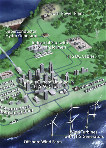
Superconductors offer solutions to these challenges, as suggested schematically in Figure 1. Their lossless current flow enables wires and cables with much higher power density than conventional copper, providing a solution to the urban capacity challenge as well as to transmitting power from distant renewable energy sources. Lossless current flow also offers increased efficiency in all grid components—cables, transformers, motors, generators, and current limiters. Power-dense superconductor generators allow cost-effective, offshore wind power, a major potential source of sustainable energy. And the fact that superconductors become resistive whenever the current exceeds a critical point provides an elegant means to limit fault currents.
Schematic electric power grid with high-temperature superconductor (HTS) power equipment. (Image courtesy of American Superconductor.)

For all of these applications, a robust, high-capacity and cost-effective HTS wire is essential. Two main types of HTS wire have been developed with existing cuprate HTS materials.Reference Scanlan, Malozemoff and Larbalestier5 First-generation (1G) wires, fabricated using the BSCCO superconductors (Bi2Sr2CaCu2O8 and Bi2Sr2Ca2Cu3O10) and a powder-in-tube deformation process similar to that for low-temperature superconductors, have a multifilamentary architecture within a silver matrix. Second-generation (2G) wires, also called coated conductors, use YBCO or its rare-earth analogs and have a thin-film HTS coating deposited epitaxially on a textured, tape-shaped template. Power applications set requirements on these wires and their constituent superconductor materials.Reference Schwall6 Here we review these requirements and identify directions for much-needed ongoing materials research.
Superconductor transition temperature T c, upper critical field H c2, and thermal effects
From an applications perspective, a superconductor transition temperature T c as high as possible is always desirable because it enables higher-temperature operation, increasing refrigeration efficiency and reliability and thereby reducing system first costs and operating costs. An additional bonus is that the specific heat of all materials is much higher at the 77 K temperature of liquid nitrogen than at 4.2 K of liquid helium. The greater specific heat impedes thermal quenching of superconductors and makes HTS wire-based systems more stable.
Cuprate superconductors with T c ≥ 90 K have thus opened the door to large-scale power equipment—a major breakthrough. Discovery of a practical room-temperature superconductor (RTS) could allow superconductor technology to have even more impact, spreading throughout the grid and possibly even into the home. However, a practical RTS is a tall order. For one thing, superconductivity that persists to such high temperatures requires a much more powerful pairing mechanism than that in existing cuprates.Reference Chu, Cardwell and Ginley7 In addition, phase fluctuations grow with increasing temperature, suppressing the global phase coherence required for superconductivity even below the pairing temperature, as discussed in the Beasley article in this issue. And because the intrinsic critical current density J c0 scales to zero at T c, T c must be well above room temperature to retain adequate operating characteristics at room temperature.
Another issue for future higher T c materials is achieving adequate tolerance to magnetic fields. The challenge here is not the classic problem of achieving a high enough superconductor upper critical field H c2.Reference Gurevich8H c2 is very high in HTS materials because it scales inversely as the square of the coherence length ξ for the superconducting order parameter, which, in turn, scales inversely with critical temperature T c.Reference Tinkham9 Indeed, existing HTS materials such as the cuprates and pnictides have H c2 values of 50 T or higher, well above the highest field of dc magnets presently envisioned, and certainly above the 0–5 T range needed for power applications.
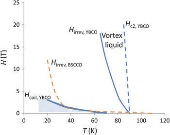
Rather, the problem is the so-called irreversibility line,Reference Malozemoff and Ginsberg10 the empirically observed contour in the magnetic-field/temperature plane where the superconductor critical current density J c drops to 0, as shown in Figure 2. Below this line, a nonzero supercurrent density is sustained by pinned or “irreversible” (though creeping) vortices (flux lines). Above the line, the pinning fails, and the material enters a vortex liquid phase with a normal, although low, resistivity. The position of the irreversibility line depends sensitively on vortex stiffness and therefore drops with increasing superconductor anisotropy. This result is well understood in terms of models based on vortex glass melting due to thermal excitation of vortices.Reference Gurevich8
Field-temperature plots of the upper critical field H c2 and irreversibility line H irrev of YBCO (yttrium barium copper oxide, in blue), and also, for comparison, the irreversibility line H irrev of BSCCO (Bi2Sr2Ca2Cu3O10, in brown). All fields are applied perpendicular to the cuprate ab-plane. The heavy dashed line, measured for an American Superconductor YBCO wire, indicates the field H coil,YBCO at which the wire achieves engineering critical-current density ≥20 kA/cm2, an approximate minimum level for practical coil design for high-temperature superconductor rotating machines. The shaded region below H coil is very limited, compared to the huge range between H coil and H irrev, where critical currents are too low. (Data for H c2 and H irrev obtained from Reference Reference Gurevich8.)

Figure 2 shows that even though BSCCO-2223 (Bi2Sr2Ca2Cu3O10) has a higher T c (110 K) than YBCO (90 K), its irreversibility line lies below that of YBCO (YBa2Cu3O7), precluding applications in even modest fields above about 40 K. Indeed, for BSCCO, an intrinsic anisotropy parameter γ of 60 or higher has been reported, while that for YBCO is only around 6.Reference Koblischka-Veneva, Sakai, Tajima, Murakami, Cardwell and Ginley11, Reference Mikheenko, Uprety, Dou, Cardwell and Ginley12 If the trend to higher anisotropy continues in new higher T c materials, it will bode poorly for their usefulness in coil-based applications. These considerations highlight the importance of understanding the role of anisotropy in HTS materials. New materials with T c in the same range as present cuprates, but with lower anisotropy, are likely to be more practical than higher T c materials with higher anisotropy.
However, tolerance to high applied fields is not enough; a more challenging problem to enable practical applications is to achieve sufficient “engineering” critical current density J e, the current density over the entire cross-section of the wire, including the substrate and stabilizer. For example, an approximate minimum J e requirement for the kinds of coils used in large HTS rotating machinery is 20 kA/cm2.
For a typical high-performance 2G YBCO wire produced by American Superconductor, the field-temperature range at which such a critical current density is achieved or exceeded is shown by the shading in Figure 2; it is limited by the dashed line labeled H coil in the figure. In the enormous region above H coil and below H irrev, the critical current density, while nonzero, is nonetheless too low for useful applications. This is why HTS rotating machinery, even with YBCO, presently needs to operate in the 30–40 K range, rather than at 77 K.
Improving vortex (flux line) pinning that sustains current density and minimizing loss of current density at grain boundaries have therefore been critical areas for ongoing research. Much progress has already been made in the cuprates. However, an even more fundamental problem for the superconductor critical current density J c, so far largely ignored in the search for higher-T c materials, is flux creep. This slow vortex motion typically gives rise to a logarithmic decay of magnetization and of persistent critical current density J c (as measured, for example, with a 1 μV/cm electric field criterion), suppressing it far below its value in the absence of flux creep, J c0.Reference Malozemoff13 In cuprates over the middle of their temperature range, this suppression is almost a factor of five, making creep one of the largest factors controlling J c.Reference Civale14 Thus, finding ways to reduce flux creep is a great opportunity for improving performance for applications and deserves much more attention.
An approximate “interpolation” formula has been used to describe the relaxation with time t:Reference Malozemoff13

where k is Boltzmann’s constant, U 0 is the pinning energy of vortices that opposes flux creep, μ is an exponent of order 1 arising from vortex glass theory, and t eff is an effective attempt time for a vortex or flux line to jump out of the pinning well.Reference Malozemoff13, Reference Malozemoff and Fisher15 In the low-temperature limit, this reduces to the classic Anderson-Kim flux creep formula, while in the high temperature limit, one finds a temperature-independent relaxation rate S = dlnJ c/dlnt = –1/μln(t/t eff), which explains the temperature-independent plateau in S observed in many forms of YBCO.Reference Malozemoff and Fisher15 In this region, J c/J c0= [U 0/μkT ln(t/teff)]1/μ.
For a given application, the chosen operating temperature T will typically scale with T c. Furthermore, in the simplest vortex-core-pinning model, U 0 ∝ H c2ξ3 is a superconductor condensation energy in a volume defined by the coherence length. Here H c is the thermodynamic critical field, proportional to the energy gap Δ and thus to T c, and the coherence length ξ scales inversely with T c;Reference Tinkham9 so one finds the vortex pinning energy U 0 scaling inversely with T c. All in all, in the high-temperature limit of Equation 1, this simple argument gives J c scaling inversely as the square of T c, which is increasingly bad news for applications as T c increases. More sophisticated collective pinning models for U 0 need to be examined as well; in such models, unless U 0 increases at least as fast as T c, flux creep will progressively diminish J c as T c increases.
In addition to theory, studying flux creep in existing materials as a function of anisotropy could elucidate these phenomena, which are of critical importance for applications. Because weak coupling between adjacent CuO2 planes in the highly anisotropic cuprates reduces vortex stiffness and thereby promotes flux creep, finding ways to decrease anisotropy while maintaining T c could enable higher J c and an increased useful H-T range. Indeed, the CuO chain layer electronically coupling adjacent to CuO2 planes makes YBCO the least anisotropic and also the most useful of the cuprates. Can its coupling strength be even further enhanced?
Critical current density for underground power cables
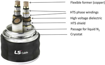
High critical current density at the desired operating conditions is the single most important requirement for power applications. But requirements vary strongly with different applications and designs. For example, ac HTS underground power cables use tape-shaped conductors helically wound (“stranded”) around a flexible cylindrical former, as shown in Figure 3. For a total operating current, these cables should use the minimum number of wires so as to reduce stranding costs and ac losses by limiting the number of winding layers to one or two. (The number of wires that can be accommodated in one layer is set by the former diameter and winding pitch.Reference Caracino, Mele, Nassi, Cardwell and Ginley16) Given the relatively low surface fields generated by these cables and their operation in liquid nitrogen to minimize refrigeration costs, high current per wire width I c,w at 77 K in the presence of its self-field is desirable. Wires carrying 250 A/cm-width or higher have been used successfully in three-phase HTS cables carrying up to 2,000 Arms.Reference Malozemoff4, Reference Caracino, Mele, Nassi, Cardwell and Ginley16 For higher amperage (e.g., 4,000 Arms cables are needed for some applications), a proportionally higher I c,w of 500 A/cm-width is needed. In contrast to coil applications (see later in text), the wire’s engineering critical current density J e= I c,w/d, which is determined by the total wire thickness d, is less critical for cable applications, because the total current is more important than the density. In fact, a relatively thick stabilizer layer (100 μm or more) is advantageous to prevent buckling under bending strains.
Cutaway of a typical underground power cable with high-temperature superconductor (HTS) tape-shaped wires wound helically around each of three cylindrical copper formers to form the three phases. Each phase conductor has two layers of HTS tapes, and around a dielectric layer, an additional one-layer shield of HTS tapes. (Image courtesy of LS Cable.)

To translate the I c,w requirement to a materials parameter such as the material’s critical current density, J c requires specifying the wire structure. For existing 1G HTS wires fabricated with a powder-in-tube technique, the BSCCO superconductor occupies up to 40% of the typically 200 μm-thick tape-shaped conductor. In this case, the I c,w = 500 A/cm-width requirement for 2-winding-layer 4000 Arms cables translates to J c = 62.5 kA/cm2, a level successfully achieved with uniaxial texturing by 1G deformation processing.Reference Rupich, Hellstrom, Rogalla and Kes17
For 2G HTS wires, adequate texturing to avoid grain boundary current limitations has required a thin epitaxially deposited film on a tape-shaped textured substrate. The corresponding J c requirement to carry the same current per width in a 1 μm-thick film is 5 MA/cm2, a level beyond the more typical 2–3 MA/cm2 achieved with biaxial texturing in existing YBCO 2G wires at 77 K.Reference Malozemoff, Yamada, Rogalla and Kes18 Higher thickness without significant loss of J c through the thickness would enable meeting this requirement; this is an active area of ongoing work on YBCO superconductors.
DC cables have their own requirements. Here, the interest is to carry high power over long distances. One design recently proposed for a 5 GW cableReference McCall, Gamble and Eckroad19 involves a bipolar configuration with two conductors carrying 12,500 A at ±200 kV, respectively. Such a huge current, if carried on helically wound tape-shaped conductors around a 25 mm diameter core, would create an azimuthal surface field of 0.2 T. In present HTS wires, such a field reduces the 77 K J c by a factor of 2 or more, causing the required number of tapes and stranding layers to more than double, increasing cost substantially.Reference Rupich, Hellstrom, Rogalla and Kes17, Reference Malozemoff, Yamada, Rogalla and Kes18 Further research on improved pinning to limit the 0.2 T field suppression of J c at 77 K is therefore much needed.
What about round wires, which would facilitate compactly wound bundles for power cables or magnet applications? Among HTS cuprate materials, only Bi2SrCa2Cu2O8 (BSCCO-2212), with its liquid-phase reaction at a moderate temperature, has been successfully developed so far to yield a round-wire form.Reference Malozemoff4, Reference Rupich, Hellstrom, Rogalla and Kes17 Unfortunately, as a 1G wire without biaxial texturing, its 77 K J c is not more than 50 kA/cm2. Ideas for round YBCO wire have been proposed as well.Reference Allais20 Compact bundled conductors also have high surface fields. For example, a 3,000 A bundle of round wires with J c = 50 kA/cm2, a 40% HTS fill factor, and a 2X safety factor would have a 0.65 cm diameter and a corresponding azimuthal surface field of about 0.2 T. For 77 K operation, this would require substantial improvement of in-field J c. What is more, in this case, the field is no longer oriented along the material’s more forgiving ab-plane, with serious consequences for ac losses (see text later). Using such a round wire in a 12,500 A dc cable with the previous J c would require a bundle of about 1.3 cm in diameter with a 0.4 T surface field, further upping the J c challenge. The requirements for such high current cables with round wires, however, can already be met at lower temperatures.
Critical current density for coils
AC coils are used in transformers and current limiters, and they can generate significant ac loss; because the high refrigeration costs to remove the excess heat are reduced at higher temperatures, ac coils of cuprate superconductors are operated typically only in a liquid-nitrogen environment. However, dc coils, such as the excitation coils on the rotors of synchronous rotating machinery, generate little loss, so the choice of operating temperature becomes a tradeoff between reduced refrigeration cost at higher temperature and increased J c at lower temperature. HTS motors and generators are therefore typically operated conduction-cooled at 30–40 K.Reference Snitchler21, Reference Kalsi, Weeber, Takesue, Lewis, Neumueller and Blaugher22
Fields produced by coils are proportional to their amp-turns; to minimize cost, the highest possible engineering critical-current density is required to increase the amperage per turn and minimize the length of wire required. Too much wire also makes the coil bulkier, neutralizing one of the main advantages of superconductor power equipment, namely high power density.
Successful operation of large dc excitation coils of HTS motors has been achieved using BSCCO-based (1G) wires with a 200 μm × 4 mm cross-section and critical currents of 250–300 A at operating temperatures in a maximum 2 T field perpendicular to the tape plane.Reference Snitchler21, Reference Kalsi, Weeber, Takesue, Lewis, Neumueller and Blaugher22 These wires were laminated on either side with 50-μm-thick supporting copper strips to improve stability. This corresponds to J e = 21–25 kA/cm2 or J c = 78.1–93.75 kA/cm2 in the tape-shaped powder-in-tube type of wire with stabilizer described previously, successfully achieved in the 30–40 K range. For YBCO-based (2G) HTS wires with a combined substrate, buffer, HTS and Ag passivation thickness of 80 μm, and two sandwiching copper stabilizer strips 50 μm thick plus 20 μm of solder, achieving the same engineering critical-current density would require J c = 4.2–5 MA/cm2 in a 1 μm-thick HTS layer. Again, such high J c in a 2 T perpendicular field can only be achieved in the 30–40 K range with present YBCO wires, and further J c enhancement is needed to extend the needed performance to higher temperatures. High field coils at 77 K are another Holy Grail, but so far, the highest fields achieved in a standalone 77 K HTS coil are only around 1 T.Reference Weijers, Trociewitz, Markiewicz, Jiang, Myers, Hellstrom, Xu, Jaroszynski, Noyes, Viouchkov and Larbalestier23 However, at 4 K, HTS conductors can enable fields well above 30 T, higher than that of any metallic low-temperature superconductor.Reference Weijers, Trociewitz, Markiewicz, Jiang, Myers, Hellstrom, Xu, Jaroszynski, Noyes, Viouchkov and Larbalestier23
AC loss
The ac loss of a superconductor wire depends strongly on the environment in which it is used, including the peak amplitude I p and frequency f of the current that it carries and the field H to which it is exposed. For example, in ac cables with helically wound tape-shaped 2G conductors, ac loss is dominated by the gaps between the neighboring conductors, and, to the extent that the wires do not conform perfectly to the circumference of the former they are wound around, by the geometry of the corners formed by neighboring wires.Reference Malozemoff, Snitchler and Mawatari24, Reference Amemiya, Jiang, Nakahata, Yagi, Mukoyama, Kashima, Nagaya and Shiohara25 For a fixed total operating current, superconductor hysteretic loss scales inversely as the square of J c, so the highest possible J c is desirable, although specific requirements depend strongly on the cable architecture.Reference Malozemoff, Snitchler and Mawatari24 Magnetic materials in some textured substrates for 2G HTS wires also contribute a ferromagnetic loss, a stimulus for further work to develop new nonmagnetic textured substrates.Reference Eickemeyer, Huhne, Guth, Rodig, Gaitzsch, Freudenberger, Schultz and Holzapfel26
A different materials requirement emerges for wires subjected to strong ac magnetic fields, as in transformers or current limiters.Reference Wilson27 At low ac magnetic fields, the superconductor hysteretic loss scales as fB p3/J c, where B p is the peak amplitude of the ac magnetic induction. If B p is high enough for flux to penetrate the superconductor completely, the hysteretic ac power loss per rms-ampere-meter is P hysteretic= afB p (mks units), where a is the filament dimension perpendicular to the field.
We first consider a field oriented along the plane of an YBCO-based (2G) HTS wire, as would occur in the center of a solenoidal magnet constructed of a stack of pancake coils. With a modest peak ac field of 0.1 Trms, and with a 1 μm HTS layer thickness and 60 Hz frequency, the predicted loss at operating temperature is only 0.008 mW/Arms·m. However, with the field oriented perpendicular to a 0.4 cm wide wire, a condition occurring at the ends of a solenoid, the same ac field level gives a much higher at-temperature loss of 33.6 mW/Arms·m. This corresponds to a required heat removal of over 1 W/Arms·m at room temperature using a typical refrigerator coefficient of performance of 0.03. By comparison, copper operating at 200 Arms/cm2 at room temperature would give a resistive loss of only 34 mW/Arms·m.
It has been known for a century that current losses in windings can be reduced by filamentizing the wire and transposing the filaments with one another along the wire length, but this is exceedingly difficult to do in a thin film. This sets a major challenge for HTS transformer applications, since one of the main drivers for HTS transformers is reduced ac loss vis-à-vis conventional copper transformers. For current limiters, a bifilar winding scheme has been shown to reduce inductance and stray fields, and thereby reduce ac loss to an acceptable level.Reference Clem28 Very fine round filaments stranded into transposed bundles with a controlled degree of electrical coupling between the filaments are a path to low-loss ac wire for magnets, but this has so far been very difficult to achieve in HTS materials. Round-wire, filamentized BSCCO-2212 is so far the closest approach to this goal, but its high anisotropy and low irreversibility field reduce its application range in multi-Tesla fields to less than 20 K.Reference Weijers, Trociewitz, Markiewicz, Jiang, Myers, Hellstrom, Xu, Jaroszynski, Noyes, Viouchkov and Larbalestier23
Mechanical, electrical, and chemical stability
Wires for cable applications must withstand high mechanical tensions and bending strains during stranding and, even more critically, the tensions arising from thermal contraction when the cable is cooled to operating temperature. First-generation HTS wires with a soft silver matrix, when unreinforced, have tensile yield stresses below 100 MPa at 77 K and are barely viable for applications.Reference Mikheenko, Uprety, Dou, Cardwell and Ginley12 Lamination with thin stainless steel strips or other reinforcement can bring the tensile yield stress to as high as 400 MPa at 77 K, meeting typical cable application requirements.Reference Masur, Podtburg, Buczek, Carter, Daly, Kosasih, Loong, Manwiller, Parker, Miles, Tanner and Scudiere29 Second-generation HTS wires generally have higher yield stresses thanks to their stronger substrates, such as nickel-tungsten alloy, Hastelloy, or stainless steel. But even here, especially for Ni-5 at% W with a 77 K yield stress of 250 MPa, lamination with reinforcing strips can be important.Reference Clickner, Ekin, Cheggour, Thieme, Qiao, Xie and Goyal30 With sufficiently thin wires with thickness, typically in the range of 200–400 μm, tensile bending strains up to 0.5%, and extraordinarily large compressive bending strains over 1.2%, can be accommodated,Reference van der Laan and Ekin31 which means that the wire can be bent around a radius of curvature as small as 4–8 cm.
Similar requirements arise in coil-based applications, plus a special requirement on tensile strains perpendicular to the tape plane (i.e., along the material’s c-axis), which arise from differential contraction between the coil and its support. The latter issue has been solved in laminated conductors by the use of solder fillets at wire edges.Reference Rupich, Li, Thieme, Sathyamurthy, Fleshler, Tucker, Thompson, Schreiber, Lynch, Buczek, DeMoranville, Inch, Cedrone and Slack32 Thus, except for the case of ultrahigh-rotation-rate (e.g., 15,000 rpm) generators that apply unusually high centrifugal forces, current HTS wires with lamination have met the mechanical requirements for power applications. New materials will have to find similar solutions.
Electrical stability against quenching of superconductors at a “hot spot” or defect, or even due to a mechanical disturbance, has been a major issue in developing practical low-temperature superconductor wires.Reference Wilson27 With HTS, this problem is significantly reduced because of the vastly higher heat capacity, although if a quench nonetheless occurs in an HTS coil, a low quench propagation velocity complicates designing an adequate coil-protection scheme.Reference Kim, Jankowski, Lee, Bascuñan, Iwasa and Fleshler33 In BSCCO (1G) HTS wire, the superconductor filaments are embedded in a stabilizing pure-Ag matrix, and in YBCO (2G) wire, appropriate laminates or electrodeposits provide a high-conductivity stabilizer.Reference Selvamanickam, Knoll, Xie, Li, Chen, Reeves, Xiong, Qiao, Salagaj, Lenseth, Hazelton, Reis, Yumura and Weber34, Reference Voccio, King, Aized, Thieme, MacDonald, Snitchler, Gamble and Malozemoff35 Wires properly tested against “dropouts” (i.e., defect locations with significantly lowered I c) have been found to be adequately stable in the liquid-nitrogen environment of power cables. The somewhat lower temperature (30–40 K) conduction-cooled environment of coils for rotating machines presents a greater stability challenge, but here too, existing wires with a high-conductivity stabilizer, either Ag or Cu, have been found to be adequately stable, as in the successful full load test of a 36.5 MW ship propulsion motor based on BSCCO (1G) HTS.Reference Snitchler21 In summary, conductor stability requirements have been met by forming composites of high-conductivity metals with the HTS material. New materials will require similar solutions.
Contamination and toxicity are more serious issues in power applications than in semiconductor electronics because of larger amounts of material involved and the risk of vaporization by the high power unleashed in a short circuit event. Superconductors for the power grid should therefore avoid toxic elements, including Tl, Hg, and Pb that are present in several cuprate families, and arsenic in the pnictides. In Europe Pb is now explicitly controlled by the European Restriction of Hazardous Substances Directive of 2003.
Any superconductor must also avoid contamination during synthesis, and contamination and decomposition during its lifetime. For cuprate superconductors, this is challenging since most elements in the periodic table poison the superconductors if allowed to diffuse into the lattice. Fortunately, the noble metals Ag, Au, and Pd are inert and do not diffuse, even at high synthesis temperatures (typically 700–800°C). Because of its relatively low (though still high!) cost compared to Au and Pd, Ag is almost universally used as the interface for electrical contacts or for forming a composite with desirable mechanical and electrical properties.
A variety of oxides can also form a stable template for the cuprates, such as rare-earth oxides and barium zirconate. Since epitaxial growth is key to 2G HTS wires, approximate lattice matching with the template oxides is also important. The tendency of YBCO to lose oxygen when directly exposed to air, even at room temperature, has been thwarted by passivating it with a thin Ag layer. Any new material needs to achieve similar chemical stability.
Cost
Perhaps the most difficult requirement for any superconductor in power applications is low cost.Reference Schwall6, Reference Malozemoff, Annavarapu, Fritzemeier, Li, Prunier, Rupich, Thieme, Zhang, Goyal, Paranthaman and Lee36 Since the amount of wire required is controlled largely by the current capacity, there is a direct tradeoff of cost with current, as reflected in the widely relevant cost-performance metric: dollars per kiloAmp-meter ($/kA·m). Here, the number of Amperes used for normalization is the current in full operation, which in cable applications is typically half the critical current. The economic viability of a given superconductor application is of course determined by the cost of all of its components, including, in the cable case for example, not just the superconductor wire but also the former, dielectric, refrigeration and control systems, supporting materials, installation, and operation. The HTS advantage in avoiding tearing up city streets by retrofitting slender high-capacity cables through existing conduits makes HTS cables an attractive solution in many cases even with present-day wire costs.
Nevertheless, a useful cost-performance benchmark for HTS can be set by comparison with copper. Material prices have varied drastically in recent years, with the spot copper price surging from $1.3/lb in January 2009 to $4.4/lb in January 2011. Assuming 100 A/cm2 maximum operating-current density in copper in underground cables, these prices, even ignoring the costs of processing to wire, correspond to 26 and 87 $/kA·m, only somewhat below the range of 150–300 $/kA·m, where HTS wire typically sells today. The present prices of HTS wires are low enough for some applications, although reducing the HTS cost differential compared to copper is part of the ongoing effort to make HTS power equipment more broadly competitive. Any new material will face a similar challenge.
The superconductor wire cost includes materials and processing costs. While commercial manufacturers do not disclose the latter, some interesting conclusions emerge from materials costs alone. Like copper prices, silver prices have surged in the last two years, from $10/oz. in late 2008 up to $30/oz. in late 2010. For the 1G powder-in-tube wires using a silver matrix constituting 60% of a 200 μm × 4 mm cross-section, silver cost per length ranges from 1.78 to 5.33 $/m. With a wire carrying 100 A (under operating conditions, about half of the highest critical currents available in commercial BSCCO 1G wires today), this corresponds to 17.8–53.3 $/kA·m. Thus the silver cost alone represents a significant fraction of the copper benchmark, undermining the long-term commercial viability of 1G HTS wire, whether tape or round. By comparison, even though YBCO 2G wires have a very thin layer of silver, nickel is by far their dominant materials component. Given that nickel’s price has risen from just below $5/lb in January 2009 to $12/lb in January 2011, a 0.4-cm-wide wire with a 75-μm-thick nickel substrate would have a corresponding nickel cost of only 2.9 to 7 cents/m, a significant cost advantage vis-à-vis 1G wire.
Conclusion
It is a truism that for a material to work successfully in a given application, it must meet all application requirements. And these are many, making materials development for applications a challenging process, usually requiring decades and causing a large assortment of initially promising materials to be winnowed down to a very few.
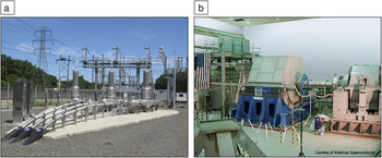
Nowhere has this been more true than in the field of high-temperature cuprate superconductors. First discovered in 1986 and now celebrating their 25th anniversary, they have proliferated into a smorgasbord of hundreds of compounds. But only a very few—YBCO, BSCCO-2212, and BSCCO-2223—have made their way into commercial wires and significant electric power grid and magnet demonstrations, such as the HTS cable and motors based on BSCCO-2223 1G wires (Figure 4). While the long-term winners have yet to be determined, YBCO in the form of 2G wire looks to be the most promising today and is already impacting the first commercial applications. It deserves strong ongoing research and development to further enhance its capabilities to meet even the most advanced requirements described in this article. At the same time, the search for a room-temperature superconductor is also important, a great challenge to human ingenuity and imagination. But more attention needs to be paid to flux creep and thermal effects, which will be major obstacles in turning such a material, even if discovered, into a practical material for the electric power grid.
(a) World’s first transmission-voltage high temperature superconductor (HTS) power cable system, installed in the Long Island Power Authority’s (LIPA) commercial power grid in April 2008. At full capacity, the 138 kV system is capable of carrying 574 MW of power and powering 300,000 homes. The three cables shown can carry as much power as all the overhead lines on the far left. (b) World’s first 36.5 MW (49,000 horsepower) HTS ship propulsion motor, manufactured by American Superconductor (AMSC) and successfully tested at the U.S. Navy’s Integrated Power System Land-Based Test Site in Philadelphia. Using AMSC’s HTS wire, the motor is one-third the size and weight of a conventional 36.5 MW marine motor. (Images courtesy of American Superconductor.)

Acknowledgments
The author thanks David Larbalestier, Jason Fredette, and Leonardo Civale for a careful reading of the manuscript and many suggestions.