NOMENCLATURE
- C
-
airfoil chord length, m
- C p
-
pressure coefficient
- H
-
shape factor
- Q
-
Q-Criterion, 1/s2
- Re c
-
chord-based Reynolds number
- U
-
streamwise mean velocity, m/s
- V
-
wall-normal mean velocity, m/s
- x
-
streamwise axial coordinate, m
- y
-
radial coordinate, m
- z
-
spanwise coordinate, m
- δ*
-
displacement thickness
- θ
-
momentum thickness
- m
-
mean
- rms
-
root mean square
- MD
-
maximum displacement
Subscripts
1.0 INTRODUCTION
Aeroengine noise pollution is a pressing regulatory issue with a great demand for increased capacity at airports, stringent local restrictions on night-time flying, and heavy final penalties for infringement of daytime noise limits. Thus, the understanding and control of engine noise is an absolutely crucial and central issue for industry. Broadband fan noise has been identified as the most significant engine contribution to noise. Furthermore, trailing-edge broadband noise is one of the most important components of the noise from fan blades and outlet guide vanes (OGV). It is generated due to the scatter of turbulent kinetic energy from the rotor turbulent boundary layer into acoustic energy at the trailing edge(Reference Ray and Dawes1,Reference Sagrado, Hynes and Hodson2) .
Aerofoil self-noise (also called trailing-edge noise) generation is representative of more complex cases such as airframe and high-lift device noise and turbomachinery noise in general. As many fundamental aeroacoustic problems have not been fully explored and understood, the accurate prediction of noise generation on an isolated aerofoil associated with proper computation of unsteady viscous flow around aerofoil still remains an outstanding problem in computational aerodynamics.
Large-eddy simulation (LES), which aims to solve numerically the larger turbulent scale fluctuations in space and time while modelling the effect of more universal small turbulent scales using a subgrid-scale (SGS) model, is a promising approach for improving our understanding of fan noise generation and providing data needed for the development of noise prediction methods. A dominant issue with LES-based methods is the interaction of discretization numerics with LES SGS models. In some cases, it can be helpful to omit the SGS model altogether where excessive dissipation occurs(Reference Ghosal3,Reference Chow and Moin4) . This is referred to here as Numerical Large-Eddy Simulation (NLES), in which the unresolved small eddies are accounted for by means of the numerical dissipation and no SGS model is employed such that the full (unfiltered) Navier-Stokes equations are solved – a procedure sometimes referred to as implicit LES.
In the present study, a wall-resolved compressible NLES approach with a high-order scheme was chosen for the numerical simulations. It was observed from experiments(Reference Sagrado5) that the boundary-layer flow around a NACA0012 aerofoil at medium Reynolds number experienced separation and transition to turbulence in the region close to the blunt trailing edge. Thus, narrowband peaks and tones associated with vortex shedding from the separated shear layer/blunt edge are superimposed onto the broadband noise induced by the turbulent boundary layer(Reference Sagrado5). This type of flow simulation can significantly benefit from the use of a high-order method due to the high computational cost involved, and also requires low numerical dispersion and dissipation(Reference Urange, Persson, Drela and Peraire6). The wall-resolved NLES approach with high-order scheme meets such requirement.
In the wider project of our research group –Aeroengine Aeroacoustic Interactions – a series of aerofoil self-noise, fan blade/rotor self-noise and rotor-wake/OGV interaction will be investigated computationally. As the first step, an isolated NACA0012 aerofoil with zero angle-of-attack at a chord-based Reynolds number Rec = 2 × 10⁵ was considered. NACA0012 aerofoil trailing-edge noise has been investigated by many researchers(Reference Herr, Ewert, Rautmann, Kamruzzaman, Bekiropoulos, Arina, Iob, Batten, Chakravarthy and Bertagnolio7–Reference Kojima, Nonomura, Oyama and Fujii12) focusing on different flow conditions and numerical methods. In the present work, the fundamental mechanism of trailing-edge noise generation and propagation were investigated by employing wall-resolved NLES and the results validated by wind tunnel test data(Reference Sagrado5), in which the same NACA0012 aerofoil case was used to investigate different aerofoil self-noise generation mechanisms of relevance to the noise from aircraft (airframe and engines) and wind turbines. The unsteady surface pressure fluctuations and the velocity field in the boundary layer and the wake of the NACA0012 aerofoil were measured and analysed(Reference Sagrado5).
In previous computational investigations in our research group(Reference Li, Peake and Savill13,Reference Li, Peake and Savill14) , a LES-SGS method was employed to evaluate LES suitability for predicting the near-field velocity field for the NACA0012 aerofoil at moderate Reynolds number Rec = 2 × 10⁵, following calculation of noise sources on, and close to, its trailing edge. The Rolls-Royce compressible CFD code HYDRA, utilising a wall-adapting local eddy-viscosity (WALE) SGS model for LES, was used in that study. Following on from this study, an incompressible wall-resolved NLES approach with a high-order scheme (up to 6th-order) was employed by Lin et al(Reference Lin, Savill, Vadlamani and Loveday15) to resolve streak-like structures in the near-wall flow regions over the NACA012 aerofoil. The capability and accuracy of the wall-resolved NLES to capture the unsteady velocity and pressure field in the near-field around the aerofoil and associated noise sources were evaluated. The effects of grid-refinement and higher-order numerical scheme on the wall-resolved NLES approach were also discussed. It was concluded that the wall-resolved NLES with a high-order scheme is capable of predicting the aerofoil self-noise sources properly(Reference Lin, Savill, Vadlamani and Loveday15).
In the present study, the wall resolved NLES numerical scheme has been upgraded and a new parallel CFD code COMP-SQUARE, implemented with compressible wall-resolved NLES, was employed for the aerofoil self-noise sources prediction. The predicted mean and rms velocity at the aerofoil trailing edge and in the wake area, and the surface pressure power spectral were compared with experimental data. The capability of compressible NLES to capture the trailing-edge noise-generation sources around the aerofoil and fan blade was assessed. The advantages of this compressible NLES code over the previous incompressible code and HYDRA LES-SGS code was discussed.
The objectives of this study included: (1) to evaluate the capability and accuracy of the compressible wall-resolved NLES approach to capture (i) the unsteady velocity and pressure field around the NACA0012 aerofoil, and (ii) the different boundary-layer regimes associated with different noise-generation mechanisms; (2) to sample and analyse the surface pressure fluctuations to provide energy spectra in aerofoil self-noise sources; (3) to produce input data of unsteady velocity/pressure sources for an analytically based far-field noise prediction scheme.
2.0 METHODOLOGY
2.1 Numerical method
In this study, simulations are performed using an in-house high-order structured code, COMP-SQUARE. To directly capture pressure waves, the three-dimensional Navier-Stokes equations are solved in their compressible form in a generalized curvilinear coordinate system as described in Ref. Reference Lin, Savill, Vadlamani and Loveday15. Only some key equations and issues relevant to the compressible flow calculations are highlighted here.
Conservation of momentum can be expressed using Equation (1):
 $$\begin{equation}
\frac{{\partial {\rm{\rho }}{{{u}}_{{i}}}}}{{\partial {{t}}}} + \frac{{\partial {\rm{\rho }}{{{u}}_{{i}}}{{{u}}_{{j}}}}}{{\partial {{{x}}_{{j}}}}} = - \frac{{\partial {{p}}}}{{\partial {{{x}}_{{j}}}}} + \frac{{\partial {{\rm{\tau }}_{{{ij}}}}}}{{\partial {{{x}}_{{j}}}}}
\end{equation}$$
The symbol ui is a fluid velocity component, ρ density, μ viscosity (evaluated from Sutherland's equation), p static pressure, t time and x the spatial coordinate. The stress tensor, τ ij , in Equation (1) is calculated using
 $$\begin{equation}
{{\rm{\tau }}_{{{ij}}}} = 2\left( {{\rm{\mu }} + {{\rm{\mu }}_{{T}}}} \right)\left[ {{{{S}}_{{{ij}}}} - \frac{1}{3}\frac{{\partial {{{u}}_{{j}}}}}{{\partial {{{x}}_{{j}}}}}{{\rm{\delta }}_{{{ij}}}}} \right],
\end{equation}$$
where δ
ij
is the Kronecker delta (δ
ij
= 1 if i = j and δ
ij
= 0 if i ≠ j). The strain rate tensor,
 ${{\rm{\tilde{S}}}_{{{ij}}}}$
, is expressed as
 $$\begin{equation}
{{{\tilde{S}}}_{{{ij}}}} = \frac{1}{2}\left( {\frac{{\partial {{{u}}_{{i}}}}}{{\partial {{{x}}_{{j}}}}} + \frac{{\partial {{{u}}_{{j}}}}}{{\partial {{{x}}_{{i}}}}}} \right)
\end{equation}$$
In conjunction with the above, the following conservation of energy equation is solved
 $$\begin{equation}
\frac{{\partial {\rm{E}}}}{{\partial {{t}}}} + \frac{\partial }{{\partial {{{x}}_{{j}}}}}({{{u}}_{{j}}}\left( {{\rm{E}} + {{p}}} \right)) = \frac{\partial }{{\partial {{{x}}_{{j}}}}}\left( {{{{u}}_{{i}}}{{{\tau }}_{{{ij}}}}} \right) - \frac{{\partial {{{q}}_{{j}}}}}{{\partial {{{x}}_{{j}}}}}
\end{equation}$$
The total energy (internal and kinetic per unit volume) is expressed as
 $$\begin{equation}
{\rm{E}} = {{\rho e}} + \frac{1}{2}{{\rho }}{{{u}}_{{i}}}{{{u}}_{{i}}},
\end{equation}$$
where e = CvT and Cv is the specific heat at constant volume. Pressure, temperature and density are related through the equation of state for a perfect gas p = ρRT. For the heat flux qj the following equation is used
 $$\begin{equation}
{{{q}}_j} = - \left( {{{k}} + {{{k}}_{\rm{T}}}} \right)\frac{{\partial {\rm{T}}}}{{\partial {{{x}}_{{j}}}}}
\end{equation}$$
In Equation (6), k is the thermal conductivity and kT = Cp μ T /PrT where Cp is the specific heat at constant pressure and PrT = 0.9 is the turbulent Prandtl number. It follows that in NLES since μ T = 0, kT = 0, the corresponding continuity equation to go with the above is
 $$\begin{equation}
\frac{{\partial {\rm{\rho }}}}{{\partial {{t}}}} + \frac{{\partial {\rm{\rho }}{{{u}}_{{j}}}}}{{\partial {{{x}}_{{j}}}}} = 0
\end{equation}$$
The inviscid, viscous fluxes and the metric terms are spatially discretized using 6th-order compact finite-difference schemes. Time integration is carried out using an explicit four-stage fourth-order Runge-Kutta (RK) scheme. It is well known that the compact schemes are non-dissipative. The numerical instabilities arising due to the non-dissipative nature of the high-order compact schemes are eliminated by filtering the conservative variables. For this purpose, an 8th-order low-pass Padé-type non-dispersive filter is employed at each RK stage. Since the filtering procedure is effective in damping out the higher frequencies, no explicit sub-grid scale (SGS) model has been employed in the simulations. This is referred to as the numerical LES strategy with μ T = μsgs = 0. Very fine grid spacing used in the near-wall region will filter out naturally the smallest turbulent scales and resolve the streak-like near-wall structures.
The code utilizes MPI message passing system for parallelization on distributed memory platforms. Mach number and Reynolds number were set at 0.17 and 2 × 10⁵, respectively, where the Reynolds number is based on the chord length and the free-stream velocity. Around 16 million (16 M) cells were used for the simulations discussed in this paper.
2.2 NACA0012 aerofoil and mesh
In the experimental investigation of Sagrado(Reference Sagrado5) into aerofoil trailing-edge noise sources, the NACA0012 aerofoil with a chord of 300 mm and an aspect ratio of 1 was placed at the exit of an open-circuit blower type wind tunnel with a rectangular cross section of 0.38 m by 0.59 m. The freestream turbulence intensity of the tunnel is 0.4%, which allows the flow on the aerofoil to initially be laminar. Two different Trailing-Edge (TE) thicknesses were investigated in the tests(Reference Sagrado5) -a sharp TE with a thickness at the trailing edge of 0.76 mm and a blunt TE produced by reducing the chord by 3 mm such that the thickness at the trailing edge was 1.6 mm. According to Blake(Reference Blake17) and Sagrado(Reference Sagrado5), vortex shedding is only noticeable in the case of a blunt TE. Vortex shedding has been identified as a main contributor to narrowband noise and tones in aerofoil trailing-edge noise generation(Reference Moreau, Christophe and Roger11).
The present computational investigation is focused on the isolated NACA0012 aerofoil with a blunt TE at zero angle-of-attack. For the compressible wall-resolved NLES, upstream inflow Mach number is set to be 0.17, corresponding to the Reynolds number Rec = 2 × 10⁵, which is based on the inlet velocity and aerofoil chord length.
The computational domain is a thin span-wise sector with a size of 20C × 10C × 0.3C, corresponding to the stream-wise, wall-normal and span-wise direction respectively, where C is the chord length. The aerofoil Leading Edge (LE) is located at x = 0, y = 0 and z = 0 with the x-axis being the stream-wise direction and the z-axis the span-wise direction. A multi-block structured C-H type mesh is generated with ANSYS ICEMCFD. It is noted that one of the significant issues with the wall-resolved NLES is the grid-resolution requirements in the near-wall regions of flow. These areas can possess small streak-like structures requiring very fine meshes of the order of (in non-dimensional wall units) Δy + ≈ 1, Δx + ≈ 50 − 130 and Δz + ≈ 10 − 30(Reference Choi and Moin18). In the current study, the wall normal C-grid lines away from the aerofoil are clustered towards the aerofoil surface boundaries with normal spacing of the first grid away from the wall corresponding to Δy + < 1, with about 30–40 cells located within the boundary layer. In the span-wise direction, the grid spacing is uniformly distributed corresponding to Δz + ≈ 25. The grid along the stream-wise direction corresponds to a spacing of Δx + ≈ 10 − 100 and is clustered towards the aerofoil LE and TE.
Mesh independence and mesh resolution effect on the wall-resolved NLES have been studied thoroughly in a previous study(Reference Lin, Savill, Vadlamani and Loveday15). It was concluded that mesh refinement was necessary for predicting accurately root mean square of velocity fluctuation and mean velocity in the wake. Turbulent vortical structure near the aerofoil TE was captured clearly with a refined span-wise mesh only. Therefore, in the current study, a refined mesh with 16 M hexahedral elements was required for the calculation. The refined mesh covers the full boundary layer, the aerofoil trailing edge and the wake up to 8% chord length, which is the region where the measured experimental data is available(Reference Sagrado5). The mesh distributions at the mid-span plane for the complete domain and locally near the aerofoil LE and TE are shown in Fig. 1.
Mesh around the NACA0012 aerofoil.

The flow in the span-wise direction was set to be periodic for the NLES. A non-slip condition was specified at the walls and the pressure gradient was zero.
3.0 RESULTS AND DISCUSSION
For the compressible wall-resolved NLES approach employed in this study, simulations were carried out with the higher sixth-order scheme based on the refined mesh. To improve stability and convergence of the compressible mode simulation, a steady incompressible mode simulation is performed first to give a realistic initial velocity field. Turbulence samples are collected after the initial turbulent flow field had settled down. The running time to gather turbulence statistics corresponds to approximately 10 flow-through times based on freestream velocity and the aerofoil chord length. In the experiments(Reference Sagrado5), aerofoil surface pressure fluctuation signals were measured by a series of microphones located between x/C = 0.42 and x/C = 0.99. They were sampled at a frequency of approximately 65000 Hz. In the compressible NLES, the surface pressure time history is sampled at the frequency of 65535 Hz, along with the turbulence flow field averaging process. To achieve this, another 10 flow-through times are run. Detailed comparisons between the experimental measurements and the computational results are presented below. To evaluate the advantage of compressible NLES over the incompressible NLES, a comparison between these two simulations with the higher six-order scheme follows below.
For the purpose of validation, the current compressible NLES is compared with experimental data(Reference Sagrado5). To show the features and advantages of compressible NLES, previous computational results from LES-SGS run with HYDRA code(Reference Li, Peake and Savill13,Reference Li, Peake and Savill14) and the incompressible wall-resolved NLES(Reference Lin, Savill, Vadlamani and Loveday15) are also plotted for comparison. The compressible HYDRA solver uses a second-order accurate-centred numerical scheme and a wall-adapting local eddy-viscosity (WALE) SGS model for LES. The solution from the HYDRA solver presented in this paper is based on a mesh size of 9 million (9 M).
3.1 Flowfield description
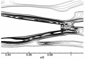
Figures 2–4 illustrate the main characteristics of the near-field flow around the NACA0012 aerofoil trailing edge. The streamlines of turbulent vorticity around the trailing edge of aerofoil is shown in Fig. 2. The vortical structure is developed within the boundary layer as it approaches the aerofoil TE. It propagates downstream and sheds at the blunt trailing edge. The vortices on the upper and lower surfaces of the aerofoil turn in opposite direction at the trailing edge creating the reversing flow in this region.
Streamlines of turbulent vorticity around NACA0012 aerofoil TE.

Iso-surface of instantaneous Q-criterion around NACA0012 aerofoil TE.

Turbulence intensity level around NACA0012 aerofoil TE.

The turbulent structures are also exhibited showing a positive value of Q-criterion, as shown in Fig. 3. Q-criterion is defined in Equation (8):
 $$\begin{equation}
Q = \frac{1}{2}({\Omega _{ij}}{\Omega _{ij}} - {S_{ij}}{S_{ij}})
\end{equation}$$
where Ω ij and Sij are the anti-symmetric and symmetric part of the velocity gradient, respectively. The Q-criterion thus represents the balance between the rate of vorticity, Ω2 = Ω ij Ω ij , and the rate of strain S 2 = SijSij . In the core of a vortex, Q > 0, since vorticity increases as the centre of the vortex is approached. Thus, regions of positive Q-criterion correspond to vortical structures. In Fig. 3, the iso-surface of Q-criterion is shown and coloured by stream-wise velocity. Towards the TE, the roll-up of two-dimensional turbulent eddies is observed due to boundary-layer flow separation and turbulence transition. It progressively becomes three-dimensional at the blunt trailing edge.
Figure 4 shows the contours of rms of stream-wise velocity fluctuation contours around the trailing edge of the aerofoil at the mid-span plane. The boundary layer over the NACA0012 aerofoil is laminar with little turbulence intensity level up to the aft part of the aerofoil, where the turbulence intensity levels increase as the adverse pressure gradient becomes larger and the laminar boundary layer progresses towards separating conditions. In the vicinity of the TE a deep re-organisation of the turbulent structure occurs and the turbulence intensity values increased further and reached their highest value at the blunt edge. The contour of rms velocity demonstrates the development of the turbulent boundary layer and substantiates the turbulent structure shown in Figs. 2 and 3.
3.2 Mean and rms fields
The static pressure on the upper and lower surface of the aerofoil is averaged in time and its distribution is defined by pressure coefficient Cp , defined in Equation (9):
 $$\begin{equation}
{C_p} = \frac{{{P_{01}} - {P_s}}}{{{P_{01}} - {P_{s2}}}}
\end{equation}$$
where P 01 is the inlet total pressure, Ps is the static pressure on the aerofoil surface and P s2 is the outlet static pressure. This definition of pressure coefficient accords with that in the experimental investigation(Reference Sagrado5). The comparison of the calculated static pressure distribution with the experimental data is presented in Fig. 5, together with the result from the inviscid flow calculation.
Pressure coefficient around NACA0012 aerofoil (AoA = 0°).

At 0° angle-of-attack (AoA), the calculated pressure coefficient agrees very well with the experimental data. The fact the results from both surfaces of the aerofoil collapse onto the same line is to confirm that the NACA0012 aerofoil is symmetrical at 0° AoA. It is also observed that both the experimental and the calculated Cp corresponding to the untripped boundary layer deviate from the data associated with the inviscid calculation in the region approximately between x/C = 0.65 and x/C = 0.97. This indicates that the flow is separating in this region and reattaching afterwards, thus creating a separation bubble in the vicinity of the TE.
Boundary layer thicknesses associated with different boundary-layer regimes were measured and analysed in the experimental investigation(Reference Sagrado5). In the computational study, the boundary-layer thickness δ has been integrated from the analysis of the mean velocity profiles. The velocity at the edge of the boundary layer Ue was defined at the point where the velocity was 99.5% of the freestream velocity. The displacement thickness δ* and the momentum thickness θ are defined in Equations (10) and (11).
 $$\begin{equation}
{\delta ^*} = \int_{y = 0}^\delta {\left(1 - \frac{{u(y)}}{{{U_e}}}\right)dy} ,
\end{equation}$$\\
 $$\begin{equation}
\theta = \int_{y = 0}^\delta {\frac{{u(y)}}{{{U_e}}}\left(1 - \frac{{u(y)}}{{{U_e}}}\right)dy} ,
\end{equation}$$
The shape factor H is defined as the ratio between δ* and θ,
 $H = \frac{{{\delta ^*}}}{\theta }$
.
In Fig. 6, the experimental and computational shape factors for the untripped boundary-layer case at Rec = 2 × 10⁵ are plotted together for comparison. The value of H at x/C = 0.4 is 2.4 for the wall-resolved compressible NLES and 2.6 from the experimental data, which are typical values for a laminar boundary layer(Reference Young19). This value increases towards the separation point (S), reaching a value of 3.67 for the compressible NLES at x/C = 0.60 and 3.25 for the experimental data at x/C = 0.65. A typical value of H at separation in a laminar boundary layer is approximately 3.5(Reference Hatman and Wang20). As Hatman and Wang(Reference Hatman and Wang16) reported, H reaches a maximum value in the region around the maximum displacement of the separated shear layer xMD . From Fig. 6, this occurs when xMD/C is approximately 0.85. In summary, Fig. 6 illustrates that the untripped boundary layer at Rec = 2 × 10⁵ is laminar up to the point where it separates due to the adverse pressure gradient, before undergoing transition along the separated shear layer and reattaching upstream of the TE. Accordingly, the shape factor H decreases sharply after the maximum displacement towards the TE to a value close to that for a turbulent boundary layer (≈1.8).
Boundary-layer shape factor on NACA0012 aerofoil (AoA=0°).

Generally, the calculated shape factor shows the same trend as the experimental data. It demonstrates the features of different regimes in an untripped boundary layer over NACA0012 aerofoil at the moderate Reynolds number Rec = 2 × 10⁵. The predicted reattachment point (R) and maximum displacement thickness point (MD) are close to the experimental data. However, the compressible wall-resolved NLES over-predicted the shape factor H value in transition and turbulence regimes and predicted separation point (S) to be approximately 7% further upstream.
The stream-wise mean velocity profiles and rms field of velocity fluctuations in the boundary layer are presented in Figs. 7 and 8 for the untripped NACA0012 aerofoil case with 0° AoA at Rec = 2 × 10⁵. The wall-resolved NLES results with 6th-order scheme from both the incompressible and the compressible codes, the HYDRA LES-SGS results and experimental data are plotted together for comparison. (Note: HYDRA data are not always available for all of the comparisons.) Four different stream-wise locations over the aerofoil, viz. x/C = 0.55, 0.65, 0.86, 0.98, are presented to demonstrate the development of different regimes in the boundary layer. In the present analysis, both the stream-wise mean velocity and the rms velocity are rescaled by local external freestream velocity.
Boundary layer stream-wise mean velocity profiles at different stream-wise locations over the NACA0012 aerofoil.

Boundary-layer rms velocity profiles at different stream-wise locations over the NACA0012 aerofoil.

In the experimental data, the boundary layer flow separates at approximately x/C = 0.65, then reattaches at x/C = 0.97, resulting in a short separation bubble. The maximum displacement (MD) area is located at x/C 0.86-0.88, and the transition region is located at x/C = 0.86-0.90(Reference Sagrado5). For the wall-resolved compressible NLES, from LE of the aerofoil up to x/C ≈ 0.65, the mean velocity profile shows a typical laminar boundary layer style with a small turbulence intensity (<<0.01), as shown in the Figs. 7 and 8. From x/C = 0.65, the boundary layer starts to separate due to the increased adverse pressure gradient, before undergoing transition along the separated shear layer and reattaching rapidly upstream of the TE at x/C = 0.98, resulting in a separation bubble matching the experimental findings. The mean velocity profile after the separation at location x/C = 0.86 shows an inflection point in the near-wall region, representing the separated reverse flow in the boundary layer. After the reattachment point at location x/C = 0.98, both the experimental data and NLES results exhibit a typical turbulent boundary-layer velocity profile, as shown in Fig. 7.
In the experimental data and the compressible NLES, the transition takes place further downstream of the separation point, in the region of the maximum displacement at x/C = 0.86-0.88. According to Hatman and Wang(Reference Hatman and Wang20), this is a typical laminar separation – short bubble transition mode, dominated by the Kelvin-Helmholtz (K-H) instability. Hatman and Wang(Reference Hatman and Wang16) found the maximum value of the rms velocity for this transition mode was approximately 0.18, which is similar to the present compressible NLES results of approximately 0.17, found in the region around the reattachment point x/C = 0.98.
It is noted that the directional insensitivity of hot-wire anemometry (employed in the measurements of the boundary-layer profiles) causes the velocity profiles to become distorted, particularly near the wall, as illustrated in Fig. 9. This distorted mean velocity profile causes the significant difference in near-wall distribution between the wall-resolved compressible NLES results and the experimental data, as illustrated in Fig. 7 at location x/C = 0.86.
Separated boundary-layer profile distortion by hot-wire measurements, Hatman and Wang(Reference Hatman and Wang16).

At all four stream-wise locations, the compressible NLES data show better match with the experimental data, while the incompressible NLES under-predicted the rms velocity. However, for the mean velocity distributions, both compressible and incompressible NLES can produce accurate data in the laminar flow regime, as shown at x/C 0.55 in Fig. 7. In the transition flow regime, incompressible NLES shows better agreement with experimental data, but cannot capture the separated flow properly, as shown in Fig. 7 at x/C = 0.86. In the turbulent flow regime (x/C = 0.98), compressible NLES shows better agreement than incompressible NLES.
HYDRA LES-SGS(Reference Li, Peake and Savill13,Reference Li, Peake and Savill14) captured the flow separation at x/C = 0.65, but predicted a stronger separated boundary-layer flow with a bigger displacement at downstream locations until flow reattachment at x/C = 0.96 (see Fig. 7).
The mean velocity and rms velocity profiles at three wake locations, viz. x/C = 1.01, 1.02, and 1.05, are presented in Fig. 10.
Stream-wise mean and rms velocity profiles at different wake locations around NACA0012 aerofoil.

The velocity profiles in the wake look almost identical above and below the extended aerofoil centre line. These symmetric profiles confirm the alignment of the aerofoil with the flow at 0° AoA. The profiles are all representative of turbulent velocity deficit. Due to the large TE thickness, the velocity can reach very small values. The turbulence intensity profile at the position very close to the TE (x/C = 1.01) shows two peaks with a sharp minimum between them, which may be related to the presence of a quasi-periodic unsteady vortex shedding from the blunt edge. It is noted that the thickness of the blunt TE (1.6 mm) is the scale of the TE quasi-periodic vortex shedding. At 15 mm downstream of the TE (x/C = 1.05), which is more than 9 times the thickness of the blunt TE, the minimum values of mean velocity and turbulence intensity have increased.
In Fig. 10, the mean velocity profiles produced from the compressible NLES compared well with the experimental data near the extended aerofoil centre line. The minimum values of mean velocity at the three locations agree very well with the experimental data. At the wake location x/C = 1.01, the compressible NLES presents clearly the two peaks of turbulence intensity with a sharp minimum between them, which agrees well with the trend in experimental data. At the other two wake locations, both incompressible and compressible NLES over-predict the turbulence intensity maximum values. HYDRA LES-SGS under-predicts the rms velocity in the same region at all three wake locations.
In Fig. 11, the wall-normal mean velocity Vm and root mean square of its fluctuation Vrms are presented for x/C = 0.98. The wall-resolved NLES results from the incompressible and compressible modes are compared with the experimental data, obtained from cross-wire measurements.
Boundary-layer wall-normal mean and rms velocity profiles over the NACA0012 aerofoil.

Generally speaking, both the incompressible and compressible NLES can predict the wall-normal mean-velocity profile very well. However, the compressible NLES over-predicts the wall-normal rms velocity profile and the incompressible NLES under-predicts the wall-normal rms velocity values.
3.3 Power spectral analysis
In the experimental investigation, stream-wise– and span-wise–distributed microphones were located for surface pressure measurements. A detailed analysis of these measurements was carried out by Sagrado(Reference Sagrado5) to help understand the nature of the wall-pressure field under the different flow regimes over the NACA0012 aerofoil, which is closely related to the aerofoil self-noise sources. In the compressible wall-resolved NLES, the surface pressure signals are collected simultaneously with the flow field averaging process, and then the Sound Pressure Level (SPL)-frequency spectral is obtained by calculating the Fast Fourier Transform (FFT) of the temporal surface pressure data.
In Fig. 12, the calculated and measured surface-pressure fluctuations in the form of SPL are presented together for comparison at four microphone locations investigated, viz. x/C = 0.61, 0.70, 0.86, 0.98. It is noted that for all the cases presented here, the SPL is plotted with respect to a reference pressure P 0 = 20μPa.
Surface-pressure power spectral from the NACA0012 aerofoil with blunt TE and untripped boundary layer.

The sharp peaks (containing energy) in the surface pressure spectral reflect the nature of the disturbances originated from the instability waves. According to Ref. Reference Hatman and Wang20, the transition to turbulence in separated boundary layers is a result of the superposition of the effects of two different types of instabilities: one is the Kelvin-Helmholtz (K-H) instability, which is associated with the separated laminar shear layer and the resultant concentration of span-wise vorticity growing in time and remaining in place through an inviscid roll-up vortex mechanism; the second is the convective Tollmien-Schlichting (T-S) instability, which is normally originated upstream of the separation point and evolves and interacts with the K-H instabilities along the separated shear layer. Hence, the separated-flow transition mechanism is the consequence of two spatially developing and competing instabilities(Reference Hatman and Wang20).
In Fig. 12, a main sharp peak is visible at a frequency of approximately 190 Hz in both the NLES and experimental results at stream-wise locations of x/C = 0.61 and 0.70. At the other two stream-wise locations of x/C = 0.86 and 0.98, the main sharp peaks do not align: approximately 175 Hz for the wall-resolved NLES and 190 Hz for the experimental data. This peak is related to the periodic vortical structures originated in the separated shear layer and is associated with the Tollmien-Schilichting (T-S) instability waves that become amplified along the separated shear layer. An expression from Stieger(Reference Stieger21) following Walker(Reference Walker22) was used in an experimental investigation to calculate the frequency of the Tollmien-Schlichting waves as 197 Hz. This is close to the frequency of the main peak found in the NLES results and in the experimental data.
The second peak in the surface pressure spectral found at frequency 200 Hz at x/C = 0.98 only in the compressible NLES and the experimental data is related to the Kelvin-Helmholtz (K-H) instabilities from the separated shear layer, as shown in Fig. 12. More often, in experimental investigations, it is observed that the T-S and K-H instabilities interact and combine resulting in the main peak(Reference Sagrado5). Hence, the peaks in the spectral seem to be part of a complex mechanism where the different instabilities interact in the separated shear layer.
The peak observed in the sound pressure spectral approximate 330–350 Hz corresponds to the first harmonic of the fundamental peak.
Through comparison in Fig. 12, it can be seen that the main peaks in the surface pressure spectral can be captured properly by the compressible NLES. The calculated frequencies at which main peaks appear agree well with the experimental observations at all four stream-wise locations presented. At locations of x/C = 0.61 and 0.70, the predicted energy contents corresponding to the first T-S waves peak agree very well with the experimental measurement. However, at the other two locations, the predicted energy contents corresponding to these peaks are over-predicted compared to the experimental investigations. Comparing the overall energy contents at different microphone locations, it can be seen that the compressible wall-resolved NLES results are agreeable with the experimental analysis in the vicinity of the TE (x/C = 0.98). This may be due to the very fine mesh resolution around the aerofoil TE. At the other microphone locations, the coarser mesh may not be able to capture all frequency elements in the spectral resulting a more deviation between the NLES and the experimental data. Therefore, a refined stream-wise mesh on the aerofoil surface is required for an accurate SPL prediction. The deviated energy content in the SPL spectral was also found in a Fluent-LES over the NACA0012 aerofoil under the same conditions(Reference Szawerdo23). In that case, the energy contents were under-predicted.
Although the flow did not separate until about x/C = 0.65, the surface pressure spectral peaks could already be seen at x/C = 0.61 (Fig. 12) and also at x/C = 0.42 (not presented in this paper) for both the experimental measurements and the compressible NLES. This is due to the fact that in this case, the waves associated with these periodic disturbances propagate upstream. This observation is in agreement with previous investigations (Brooks et al(Reference Brooks, Pope and Marcolini24), Oerlemans and Migliore(Reference Oerlemans and Migliore25), Roger and Moreau(Reference Roger and Moreau26)) on aerofoils with a laminar boundary layer, with a feedback loop between the aerofoil TE and an upstream source where the T-S waves originate.
It is also found, in both the experimental data and the compressible NLES, near the TE and after the transition takes place along the separated shear layer, the energy content at high frequencies increases.
In Fig. 12, there is no clear evidence of vortex shedding from the TE presented in the spectral. This might be due to the short distance of the reattachment point upstream of the TE. The vortex shedding from the TE is not fully developed yet and might be concealed by the stronger vortex shedding from the separated shear layer. The periodic disturbances associated with tonal peaks and shed from the separated shear layer remain dominant in the flow.
4.0 CONCLUSIONS
An accurate numerical prediction for the near-field flow around an aerofoil/fan-blade and the wake flow development is of outstanding importance for self-noise and downstream broadband noise prediction. This has been identified as a significant contributor to modern High-Bypass Ratio (HBR) engine noise.
In this study, a wall-resolved compressible NLES approach is employed to predict the near-field flow, particular boundary-layer flow transition over an isolated NACA0012 aerofoil with zero angle-of-attack at Rec = 2 × 10⁵ and Mach number = 0.17. The capability of compressible wall-resolved NLES to capture the unsteady flow features and turbulence transition over the NACA0012 aerofoil is assessed; the boundary-layer mean velocity, the turbulence intensity, and the surface pressure spectral are validated against experimental data. The advantage of the compressible NLES over the incompressible NLES is discussed.
The comparisons between computational results and experimental data show that the wall-resolved compressible NLES approach with a 6th order discretisation scheme is able to capture the boundary-layer flow features around the aerofoil and the downstream wake flow with a sufficient accuracy for meaningful aeroacoustic analyses. The calculated turbulent vorticity and turbulence intensity levels around the TE of the NACA0012 aerofoil represent the instability waves and turbulence structures development in the boundary-layer flow due to the adverse pressure gradient. The surface pressure distribution shows good agreement with experimental data. The mean velocity distributions from the compressible wall-resolved NLES show better agreement with experimental data in laminar and turbulent flow regimes, while less accurate than the incompressible wall-resolved NLES in transition flow regime. However, at all stream-wise locations, the compressible NLES predict better rms velocity distribution than the incompressible NLES. The integrated boundary-layer shape factor exhibits correctly the boundary-layer flow maximum displacement point, transition point and reattachment point, but a minor deviation on the boundary-layer flow separation point. A short separation bubble is clearly observed in the experiments and in the compressible NLES. Both the experiments and the NLES proved that the boundary-layer transition is laminar separation – short bubble transition mode, dominated by the Kelvin-Helmholtz (K-H) instability. The surface pressure time history signals are sampled and analysed in this study. The sound pressure spectral agrees well with experimental data in terms of the main peaks associated with the Tollmien-Schlichting (T-S) and Kelvin-Helmholtz (K-H) instability waves developed in the separated boundary layer. For an accurate sound pressure level (SPL) energy content prediction, a refined stream-wise mesh on the aerofoil surface is required.
From the studies of Li et al(Reference Li, Peake and Savill13,Reference Li, Peake and Savill14) and Lin et al(Reference Lin, Savill, Vadlamani and Loveday15) in conjunction with the study in this paper, the 2nd-order LES-SGS and the 6th-order wall-resolved NLES approaches have been rigorously evaluated in terms of their capability to predict the boundary-layer flow over a NACA0012 aerofoil at a moderate Reynolds number, Rec = 2 × 10⁵, and aerofoil self-noise sources around the trailing edge of the aerofoil. It is concluded that a wall-resolved compressible NLES with 6th-order discretisation scheme and a refined mesh is highly recommended for the correct computational simulations of the aerofoil/fan-blade self-noise sources.
The study in this paper is not the final goal but an important step of a larger project on Large-Eddy Simulation (LES) of aeroengine aeroacoustic interactions. The implementation of the wall-resolved compressible NLES provides a promising approach for a hybrid prediction scheme for fan wake –OGV broadband interaction noise and duct noise propagation; with the understanding that the pressure prediction needs to be very accurate in order to give good SPL prediction.
The recommendation for the next stage of the of aeroengine aeroacoustic interactions project is to input the pressure fluctuation data collected around the aerofoil/fan blade trailing edge into an analytically based noise prediction scheme based on Ffowcs Williams and Hawkings (FW-H) formulation for the far-field broadband noise prediction.
ACKNOWLEDGEMENTS
The authors gratefully acknowledge UK Engineering and Physical Sciences Research Council (EPSRC), funding via Grant EP/I101022X. The computer time was provided through the Cranfield High Performance Computing Facilities (HPCF) Astral Supercomputers. The authors are also greatly indebted to Dr. Tom Hynes from Cambridge University for supplying the experimental data from the PhD work of his student Ana G. Sagrado.