NOMENCLATURE
- CD
-
drag coefficient
- CL
-
lift coefficient
- CL max
-
maximum lift coefficient
- CM
-
pitching moment coefficient
- CP
-
pressure coefficient
- CFRP
-
carbon fibre reinforced plastic
- LUSM
-
linear ultrasonic motor
- FE
-
finite element
- SMA
-
shape memory alloy
- MFC
-
microfibre composite
- USM
-
ultrasonic motor
- x
-
location along chord from leading edge
1.0 INTRODUCTION
In order to facilitate take-off and landing and accomplish various manoeuvres, the aerodynamic forces on the wings of a flying vehicle need to be adjusted. This can be achieved by changing the camber of the wing. Conventionally, wing camber is changed using hinged control surfaces, which lead to high local surface curvature, where the flow tends to separate and causes an excessive drag. Therefore, large hinged control surfaces such as flaps are not likely to be used on a regular basis, and this imposes constraints on the size of flight regime of the vehicle.
Wing morphing, which enables changes in aerofoil geometry while maintaining a continuous and smooth aerodynamic surface, has the potential to improve aircraft performance( Reference Kota, Osborne, Ervin, Maric, Flick and Paul 1 - Reference Thill, Etches, Bond, Potter and Weaver 3 ). Among various morphing design concepts, a continuous change in camber provides a way of improving aircraft fuel efficiency and mission capability( Reference Kota, Osborne, Ervin, Maric, Flick and Paul 1 , Reference Campanile and Sachau 4 , Reference Campanile and Anders 5 ). Wind-tunnel tests have shown that by replacing a hinged flap with a morphing trailing edge, the L/D (lift/drag) ratio of a 2D aerofoil could be increased by 20–25%(Reference Kota, Hetrick, Osborn, Paul, Pendleton and Flick6,Reference Woods, Bilgen and Friswell7) .
The idea of morphing aerofoil was put forwarded in the 1920s and has attracted renewed interest in recent years. However, published aerodynamic data on the performance of morphing aerofoils is still not abundant. Moreover, most researchers have focused on investigating the improvement of aerodynamic efficiency via replacing the hinged flap with a smooth morphing structure. In contrast, the potential of morphing aerofoils to form camber lines with different shapes, which offer multiple morphing strategies (configurations), are often overlooked.
The structural design for a morphing trailing edge is challenging since contradicting requirements such as flexibility, load-carrying capacity and light weight need to be satisfied(Reference Schroeder and Wayman8,Reference Trease and Kota9) . Nevertheless, a few practical concepts are available. For example, the topology synthesis method can be utilised to design compliant structures that are capable of performing desired morphing under a simple actuation displacement without causing a significant strain while satisfying other design constraints(Reference Kota, Hetrick, Osborn, Paul, Pendleton and Flick6,Reference Rediniotis, Wilson, Lagoudas and Khan10) . It has been reported that a morphing trailing edge designed by such a method is capable of providing ±10° flap deflection, 1°/foot twisting along the span and a satisfactory loading capacity( Reference Kota, Osborne, Ervin, Maric, Flick and Paul 1 - Reference Thill, Etches, Bond, Potter and Weaver 3 ). An adaptive “belt rib” concept is designed to replace the conventional ribs. It consists of a closed shell (belt) and in-plane spokes that are hinged to the shell( Reference Kota, Osborne, Ervin, Maric, Flick and Paul 1 , Reference Campanile and Sachau 4 , Reference Campanile and Anders 5 ). Such a structure is naturally flexible and allows morphing with a single degree of freedom. Meanwhile, studies have shown that boundary layer can be stabilised to delay flow separation by replacing a wing's rigid upper skin in front of the conventional hinged aileron by an adaptive composite skin that is actuated along the out-of-plane direction( Reference Georges, Brailovski, Morellon, Coutu and Terriault 11 - Reference Gabor, Koreanschi, Botez, Mamou and Mebarki 13 ). An array of actuators beneath the skin is used to deform the skin into different shapes optimised for various flight conditions. Similar structures can also be used on other parts of the wing and to achieve drag reduction( Reference Gabor, Koreanschi and Botez 14 - Reference Gabor, Simon, Koreanschi and Botez 16 ).
Selection of a morphing actuator that is lightweight, small in size, power-efficient and fail-safe is another challenge. A smart material actuator that can directly convert electrical, magnetic or thermal stimulation to mechanical displacement is believed to offer a way to satisfy some of these requirements(Reference Woods, Bilgen and Friswell7,Reference Smith17) . The most widely studied smart materials for actuation include shape memory alloys (SMA) and piezoelectric ceramics. However, SMA has a limited maximum strain of 8%, and its two-way shape memory effect fades out as it cycles(Reference Schroeder and Wayman8,Reference Trease and Kota9) . Also, although SMA can be fast-reacting, the speed of activation and deactivation relies on the heating rate and cooling conditions, which impose a barrier to high-frequency operation(Reference Kota, Hetrick, Osborn, Paul, Pendleton and Flick6,Reference Rediniotis, Wilson, Lagoudas and Khan10) . Furthermore, their power consumption can be increased significantly as a result of cooling(Reference Lockyer, Marchtin, Lindner and Walia18). Piezoelectric ceramic can output large force at high speed and frequencies, and it has a power density 100 times that of SMA(Reference Tieck, Mohanchandra and Carman19). Although the maximum strain of piezoelectric ceramic is only ~0.1%, they are usually used as microfibre composite (MFC) to bend thin structures(Reference Barbarino, Bilgen, Ajaj, Friswell and Inman2), and they can be an attractive option if the actuation displacement could be amplified without sacrificing the actuation force.
In this paper, a new morphing design concept is presented and it is applied to an asymmetrical aerofoil (NACA 4418). A compliant truss structure that has multiple truss elements hinged to a compliant upper skin forms the morphing structure. The actuators between truss elements are controlled independently to allow continuous camber change with multiple degrees of freedom. A linear ultrasonic motor based on piezoelectric ceramics is proposed as the morphing actuator, and it can potentially provide unlimited linear output while retaining the high actuation force. It also copes well with the challenge of morphing since the runners can be compliant and multifunctional to serve as the structural components. Our numerical simulations and wind-tunnel tests show that besides the widely recognised benefits of a morphing aerofoil over hinged control surfaces, the vehicle flight regime can be further extended by switching between different morphing strategies and allowing the pitching moment control independent of C l.
2.0 THE PROPOSED MORPHING AEROFOIL CONCEPT
2.1 Linear Ultrasonic Motor (LUSM)
In a typical LUSM, pieces of piezoelectric ceramics are used to generate vibration at ultrasonic frequencies and form a travelling wave. The travelling wave can drive a body in contact with the ceramics through friction; therefore, the high-frequency displacement from the piezoelectric ceramics can be converted into a constant linear velocity. In this way, the limited actuation displacement of the piezoelectric ceramics is amplified to a theoretical infinite without necessarily sacrificing actuation, making a competitive morphing actuator possible. Also, when the LUSM is powered down, the piezoelectric ceramics could inherently hold the runner and provide blocking force, which makes it fail-safe. However, LUSM is rarely reported being used in morphing structures.
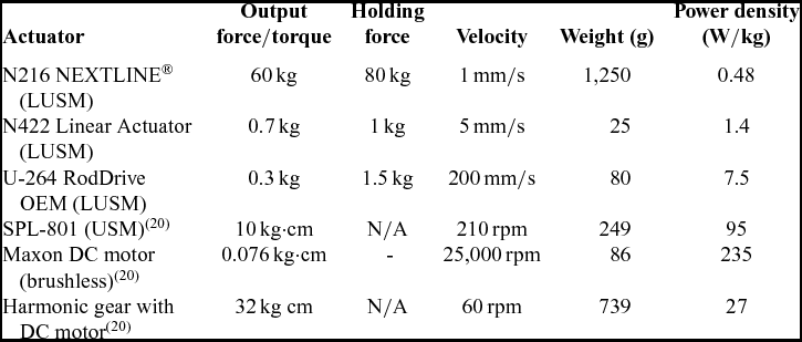
In Table 1, three off-the-shelf LUSMs are set in comparison with revolving ultrasonic motors (USM) and electric motors that have been reported in literature(Reference Bartley-Cho, Wang, Marchtin, Kudva and West20). In terms of power density, which is a critical parameter for morphing actuators, LUSM is not attractive. However, the main reason for this drawback is that LUSM is currently developed as a positioning device due to its intrinsic fast response and high open-loop precision, rather than as a heavy-duty actuator. There is a significant room for further improvements, such as in weight reduction and power enhancement. It has been reported that the power of ultrasonic motors could be increased for instance by fine-tuning the driver frequency(Reference Tieck, Mohanchandra and Carman19,Reference Bartley-Cho, Wang, Marchtin, Kudva and West20) .
Actuator comparisons(Reference Bartley-Cho, Wang, Marchtin, Kudva and West20)

Meanwhile, DC motors usually need a transmission mechanism to reduce the speed, which significantly decreases power density. For example, the power density of DC motor in Table 1 is reduced from 235 W/kg to 27 W/kg when a harmonic gear transmission system is used(Reference Bartley-Cho, Wang, Marchtin, Kudva and West20). This will also lead to an increased space occupation and a reduced reliability.
Therefore, LUSM has the potential to be a future morphing actuator solution, especially when space is strictly limited, such as in miniature unmanned aerial vehicles (MUAV), or when a large number of actuators is needed to control numerous degrees of freedom.
2.2 The proposed concept: compliant runners driven by LUSM
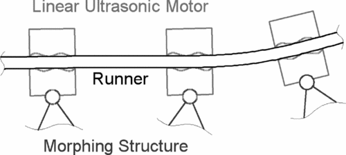
The LUSM requires a compliant runner that can provide effective contact with the piezoelectric actuator. Keeping this in mind, an actuation system with multifunctional compliant runners driven by LUSMs is proposed, as shown in Fig. 1. Since a homogeneous compliant runner naturally maintains a smooth curvature under bending and is able to provide out-of-plane stiffness and axial stability, it is an ideal actuator for a morphing wing in which a smooth aerodynamic surface, structural compliance and loading capacity are required.
Schematic view of the actuation system concept with a compliant runner and LUSMs, where LUSMs are pivoted onto the actuated morphing structure and the runner naturally forms a smooth curvature.

As shown in Fig. 1, multiple LUSMs pivoted to a morphing structure with multiple degrees of freedom could run along the same runner. Therefore, all the degrees of freedom can be controlled and a smooth curvature can be formed. Such an actuation system can be integrated into various morphing structures as a universal actuator solution.
When used on the surface of a morphing wing, it is necessary for it to be airtight. This can be achieved by applying morphing skins, such as segmented compliant panels or elastomers, which can passively slide along the runner.
Also, besides the actuation and the structural capacity, more functionality can potentially be embedded into the runner due to its unique position. For example, sensors such as optical fibres can be used to monitor the curvature of the runner, and electronics can be embedded in the runner, thus converting it into a data link between the controller and a large number of actuators.
2.3 The morphing structure
In the morphing aerofoil, the actuation system needs to be supported by a morphing structure that can change shape under actuation, provide loading capacity by eliminating the unwanted degrees of freedom and form the aerodynamic profile. In this research, the baseline NACA 4418 aerofoil was selected because of its relatively high thickness and near-flat lower surface, which makes it easier to manufacture and implement the morphing actuation system.
A carbon fibre composite morphing structure with compliant truss is proposed. As shown in Fig. 2, the morphing aerofoil consists of a rigid wing box (which ends at 40% chord), a flexible upper skin, four independent compliant truss elements and a rigid trailing edge. The actuation system is used as the lower skin of the aerofoil. The LUSMs are positioned at the bottom apex of truss elements, which are hinged to the upper skin. One or more runners are fixed to the trailing edge and slide through the LUSMs as described in Section 2.2. The truss elements shown in Fig. 2 have a span-wise shift to prevent interference with neighbouring trusses with a lower vertex angle between trusses of 60°. This is a compromise between overall structural stiffness and the number of truss elements; it also reduces the thickness mismatch between the rigid wing box and the morphing section under large deflection. The number of actuators is equal to the number of truss elements, spaced equally along the runner.
Schematic view of the morphing aerofoil concept with the compliant truss configuration and the proposed LUSM actuation system. The system provides five degrees of freedom.

When the truss elements are sliding along the runner, the morphing structure will bend or straighten and the camber of the aerofoil will change. During morphing, the flexible composite upper skin and the runners on the lower skin will maintain smooth curvature that guarantees aerodynamic efficiency. The truss elements will also undergo small elastic deformation that can be accommodated by their compliance.
A major advantage of this morphing structure is that it can morph with multiple degrees of freedom and thus provides a wide range of camber line shapes, which is enabled by the independent actuation of the four truss elements as well as the rigid trailing edge by the five sets of LUSMs. Meanwhile, the CFRP truss structure naturally possesses high specific stiffness and strength, and provides adequate loading capacity. For the same reason, low bending stiffness of the structural elements is allowed, which leads to low resistance to camber morphing.
2.4 Simulation of Morphing Process
A nonlinear FE simulation is carried out to show the morphing process of the proposed aerofoil and to assist later analysis.
A 3D model of the morphing aerofoil is constructed with a 280 mm chord and 5 mm span. All materials are assumed to be linear, elastic and isotropic. The upper carbon fibre reinforced plastic (CFRP) skin is 0.25 mm thick (E = 100 GPa, ρ = 1.6 g/cm3), the trusses are made of 0.5 mm thick CFRP plate, the lower joints of trusses are plywood (E = 800 MPa, ρ = 0.7 g/cm3), the runners are CFRP rods of 1 mm diameter (E = 100 GPa, ρ = 1.6 g/cm3), and the LUSM are replaced by CFRP plates. The lower morphing skin is not included since it should not have significant effect on the morphing process. The model has the same material properties and dimensions to the prototypes discussed in Section 5, except that it is a near 2D model with a 5 mm span and only one runner is included.
In the analysis, the hinges between the truss and upper skin are assumed to provide no bending resistance. Sections of runners are fixed between adjacent actuators, and actuation is represented by thermal contraction/expansion of the runners. This does not resemble the interface between the piezoelectric ceramic and the runner, but it fully replicates the conditions of the morphing structure under actuation (while ignoring small change of the runner's diameter) and significantly saves computational time. The thermal contraction of different sections of runners can be controlled independently, so all five degrees of freedom can be manipulated.
The structural weight (excluding the wing box) from the simulation is 22 grams, which is equivalent to 440 grams per meter span, and the morphed shape, as shown in Fig. 3, is smooth. However, slight waviness can be seen in the upper and lower skins, which is captured in both the analysis models and wind-tunnel test models. According to the literature(Reference Jacobs21), lift and drag are barely influenced by an upper surface protuberance located after the middle chord with a height of up to 0.5% of chord length; thus, this waviness is expected to have a minor effect on the morphed aerofoil's performance. More morphing configurations are shown in Section 3.
Finite-element simulation illustrating a morphing configuration with near-maximum trailing-edge deflection.

2.5 Numerical simulation of loading capacity
Achieving sufficient load carrying capacity is an additional objective of morphing aerofoil design. As a preliminary assessment, a nonlinear static FE simulation is carried out to test the model aerofoil's loading capacity.
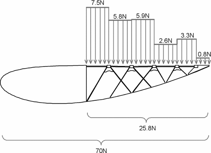
The model has the same material properties and dimensions to the one used in Section 2.4, except that the span is 50 mm, and 10 rods with 5 mm spacing are included, making it identical to the static prototype discussed in Section 5. The aerodynamic load is assessed with the 2D Xfoil code (see Section 3), then the load distribution on both sides of the aerofoil is integrated into six forces evenly distributed within 6 adjacent regions on the lower surface of the morphing part, and then the forces are applied to the same regions of the 3D structural model. The six regions are divided by the actuators and trailing edge, as shown by Fig. 4. This loading condition is identical to the static loading test on the prototype built in Section 4. There is no direct load on the upper surface since the aim here is to evaluate the load-carrying capacity of the truss structure, while the behaviour of the upper skin can be modified as needed if bigger models were constructed; the objective is to illustrate the morphing concept and demonstrate it in a small physical model.
Chord-wise load distribution used in the static load simulation with an overall load of 70 N.

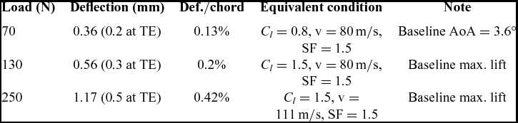
Three different loading conditions with the whole aerofoil carrying 70 N, 130 N and 250 N load are simulated. No large deformation is observed, and the results are listed in Table 2, where both the maximum deflection across the aerofoil and the deflection of trailing edge are reported, and the ratio of maximum deflection in chord length is also reported to show the extent of deformation. Three equivalent flight conditions are included in Table 2 to provide an idea about the possible flight regime. It should be noted that the load here represents the overall load across the whole aerofoil, and the morphing part only carries 26 N, 48 N and 93 N loads respectively, since most of the aerodynamic force is generated near the leading edge.
Results of the static structural simulation

SF = safety factor, which is applied to force; TE = trailing edge; AoA = angle-of-attack.
3.0 AERODYNAMIC PERFORMANCE
Unlike conventional hinged flaps, the morphing aerofoil always maintains a smooth surface, and it can be controlled with multiple degrees of freedom. In order to investigate the aerodynamic impact of these features, aerodynamic analysis and wind-tunnel tests are carried out to evaluate the performance of the aerofoil (with a baseline profile of NACA 4418) at different morphing configurations and flight conditions (different angles of attack).
3.1 Morphing strategies
The multiple degrees of freedom of the proposed morphing aerofoil can be used to generate different morphing configurations. This can be done by controlling the five sets of LUSMs independently in reality, or assigning the thermal expansion of the five rods independently in the structural simulation, as discussed in Section 2.4.
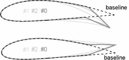
The morphing leads to camber change, and multiple actuators along the chord can alter the curvature of the camber line at different chord-wise locations. At a constant trailing-edge deflection, different morphing settings yield aerofoils with different camber line shapes (Fig. 5). There is an infinite number of possible morphing shapes; for an aerofoil with camber increased at one location, that location can be continuously moved along the chord by adjusting the output of different sets of actuators. As shown in Fig. 5, two intuitively defined morphing strategies and a conventional hinged flap are considered:
-
• Strategy 1: Morphing aerofoil with camber intensively changed near the maximum thickness and an unchanged trailing edge
-
• Strategy 2: Morphing aerofoil with camber intensively changed near trailing edge
-
• Strategy 0: Aerofoil with a hinged flap at 0.75 chord length.
2D aerofoil models at 0˚ angle-of-attack with three different morphing strategies.

The 2D aerofoils shapes for aerodynamic analysis are generated using the 3D models resulting from the structural simulations. In the structural simulations, the ratio between the amounts of runner expansion is kept constant for each morphing strategy to realise different trailing-edge deflection with a similar camber line shape.
3.2 Aerodynamic analysis set-up
3.2.1 Xfoil analysis
Xfoil is a code widely used in research to analyse the flow around a subsonic aerofoil. It is based on a revised 2D panel method that takes into account the viscosity and compressibility effects, allowing reasonable predictions of lift, drag and pitching moment, as well as the flow separation point beyond the stall angle(Reference Mack, Brehm, Heine, Kurz and Fasel22,Reference Gross and Fasel23) . In the literature(Reference Koreanschi, Sugar-Gabor and Botez24), a morphing wing with adaptive upper skin has been tested in wind tunnel at Reynolds numbers similar to those in the present research. The tests use 14–16 pressure taps to measure the pressure distribution on the aerofoil, and the results are then used to determine the location of flow transition. The comparison to Xfoil analysis has shown a close agreement on surface pressure coefficients and transition occurrence.
The computational analysis discussed in the following sections is performed with Xfoil at Reynolds number Re = 1.5 · 106 (based on the aerofoil chord length) and Mach number M = 0.235. This is representative of a 28 cm chord length mini UAV flying at sea level. An analysis with Re = 0.5 · 106 and M = 0.078 is carried out to match the condition of wind tunnel tests.
3.2.2 Wind-tunnel tests
To support the simulations, wind tunnel tests have been performed at a free-stream velocity of 25 m/s and the Reynolds number Re = 0.5 · 106. Using multiple rigid models, seven different aerofoil morphing states are tested, including: baseline (strategy 0 with 0 mm deflection), strategies 0, 1 and 2 with 30 mm downward and 20 mm upward deflections.
3.2.2.1 Model construction
Rigid models with a 280 mm chord (same as in aerodynamic analysis) and a 600 mm span and cross-sections representing different morphing states are made by laying up glass fibre cloth with epoxy onto a reinforced foam core, forming a skin of ~0.5 mm thickness. The foam core is shaped by a CNC hot-wire cutting machine with the tolerance of around 0.5 mm due to material burn-off. All the models are polished with P180 sandpapers to give a fairly smooth surface finish.
The hinged aerofoil model has a movable flap which is attached to the fore body via three hinges along the span. The flap has a circular leading edge that can just fit into the concave slot in the rare part of the fore body to eliminate all gaps between the fore body and the flap. This ensures the aerofoil surface to be as smooth as possible (with fluctuation height near the junction < 1 mm) and no air can escape from the lower surface to the upper surface.
3.2.2.2 Wind-tunnel set-up
The aerofoil is tested in the Project tunnel at University of Manchester. The tunnel has an octagonal test section measuring 87 cm × 111 cm (height × breadth). To ensure a 2D flow around the aerofoil, the aerofoil model is mounted between the two splitter plates spanning the whole width of the test section. The function of splitter plates is to isolate the tips of aerofoil models from the tunnel wall boundary layers and to ensure a near 2D aerodynamic behaviour. A 2 mm gap is left between the splitter and each end of the aerofoil for clearance. The aerofoil model is mounted to a six-component load balance through a sting, which passes through a hole in the upper splitter plate.
The speed measured at the original test section inlet cannot be used since the complicated blockage effect caused by the splitter plates, test model and tunnel wall will alter the flow velocity between the splitters(Reference Giguere and Selig25). The free stream speed is determined instead with a Pitot tube located between the splitters at 11 cm away from the sidewall and 60 cm upstream of the aerofoil leading edge.
The test points are recorded by a computer program that averages the data sampled at 1 kHz during a second. To further reduce the fluctuation, each data points reported in this paper is the average of five repeated tests.
The maximum total blockage effect, including the contribution of solid blockage and wake blockage, is lower than 3.5%. All the test data reported in this paper have been corrected for blockage effect and lift effect, as well as circulation effect that account for a change up to 7% in the measured dynamic pressure due to proximity of the pitot tube to the aerofoil model(Reference Giguere and Selig25,Reference Pankhurst and Holder26) .
3.3 Aerodynamic results
3.3.1 Results on aerofoils with an increased camber
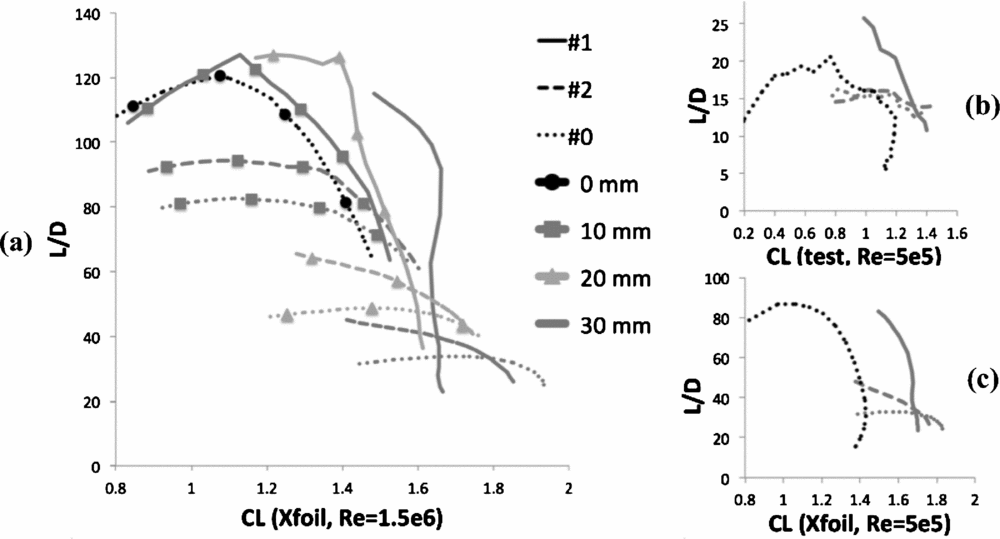
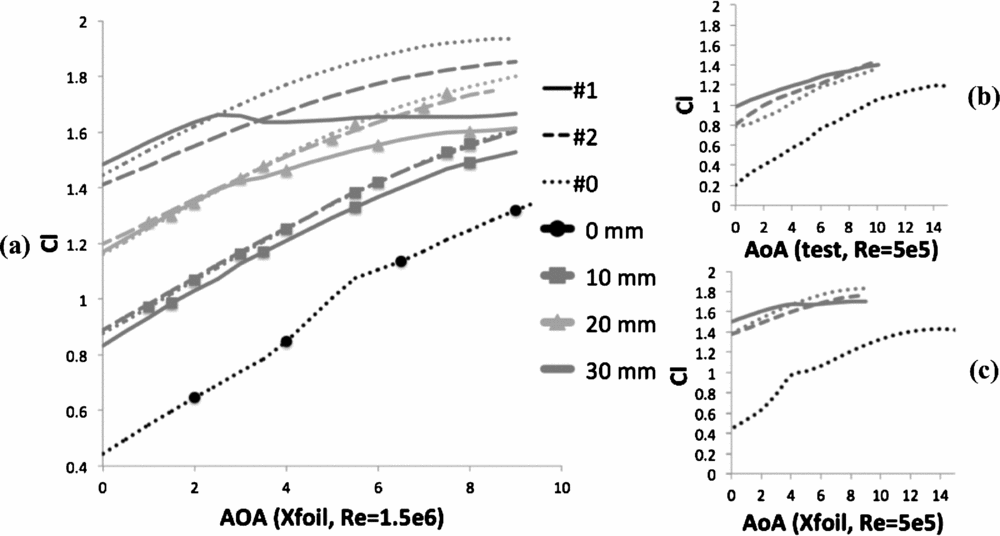
Before moving on to a detailed discussion of the result, it is worth explaining the function of the layout of Figs. 7 and 8. Each of these figures has set three subplots in comparison. The subplots represent the results from Xfoil analysis at two different Reynolds numbers and the wind-tunnel test, respectively. Figure 7(a) shows the results at Re = 1.5 · 106, which is representative of a UAV. The key results can be derived from this figure but still require experimental validation. Figure 7(b) shows the results from the wind-tunnel tests, which are carried out at a lower Reynolds number of 0.5 · 106, due to the constraint of test models and equipment; this included only one deflection due to the time limitation. However, it is sufficient to support the analysis results if the Reynolds number effect is not significant. Therefore, Fig. 7(c) is plotted, which shows the analysis results at the test Reynolds number. By comparing it to Fig. 7(b), it can be seen that the curves from the test and the analysis results show very similar trends despite the difference in magnitudes that is discussed later. The comparison between Fig. 7(c) and Fig. 7(a) shows that the Reynolds number effect has causes no significant change in the trend of the curves. Therefore, the trend of the curves shown by Fig. 7(a) is supported by experimental results (and similar for Fig. 8(a) and for the results discussed in Section 3.3.2), and the key conclusions on the effects of different morphing strategies can be made.
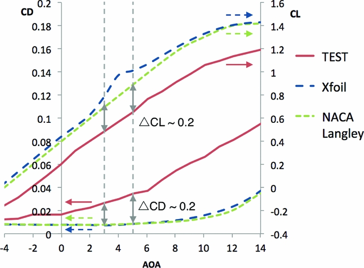
The difference in the results’ magnitudes is mostly caused by the way that lift and drag are measured, which includes the test model's 3D effects. In Fig. 6, lift and drag results of the baseline aerofoil NACA 4418 from the wind-tunnel test, Xfoil analysis and NACA Langley wind tunnel(Reference Abbott, Von Doenhoff and Stivers27) are compared. As shown in the figure, the analysis shows good agreement with NACA test results, but the test results in the presented research shows differences. For instance, within an angle-of-attack range of 3°~5°, the CD is approximately 0.02 greater and CL is around 0.2 lower.
Comparisons between lift and drag coefficient of the baseline NACA 4418 aerofoil from the present wind-tunnel test (Re = 0.5 · 106), Xfoil analysis (Re = 0.5 · 106) and NACA Langley wind-tunnel test (Re = 3 · 106)(Reference Abbott, Von Doenhoff and Stivers27).

In the NACA test, the lift is deduced from the pressure distributions measured on the aerofoil surfaces, and the drag is evaluated from the pressure in the wake(Reference Abbott, Von Doenhoff and Stivers27). Such methods allow the measuring devices to be placed near the centre of the wing span(Reference Wolken-Möhlmann, Knebel, Barth and Peinke28), and hence the 3D effect can be significantly reduced, whereas in the present wind-tunnel test, all the forces are measured directly with the force balance and the forces on the wing tips are included. The mechanical clearance between the wing tips and splitters causes 3D effects that increase drag and reduce lift that leads to the difference in the results.
To briefly summarise the observations from the results, when the morphing strategy changes from strategy 1 to 2 and finally to strategy 0, which is the aerofoil with a hinged flap, the location of maximum camber increment moves towards the trailing edge and the maximum curvature of the camber line increases. It is shown by the results that when such changes are made, the aerofoil tends to be more efficient (higher L/D) at higher angles of attack and less efficient (lower L/D) at lower angles of attack.
In Fig. 7, L/D ratio is plotted against CL, which shows that at each trailing-edge deflection, morphing strategy 1 yields the highest L/D ratio among the three configurations within the lower range of CL tested, but its L/D drops more rapidy than other strategies at higher CL , which is obviously associated with a rapid increase in CD . It can be seen in the figure that CL can be increased by increasing trailing-edge deflection. Morphing strategy 1 is the most efficient until CL is over ≈1.7 with a maximum trailing-edge delfection of 30 mm. Morphing trategy 2 gives the highest L/D ratio until CL ≈1.8. At higher CL values, strategy 0, is the better performing morphing configuration.
L/D -CL curves of aerofoils with increased camber and different trailing-edge deflections, showing morphing strategies outperforming hinged aerofoil (dotted lines) and outperforming each other at different CL range, all aerofoils except the baseline have 0°~10° angle-of-attack.

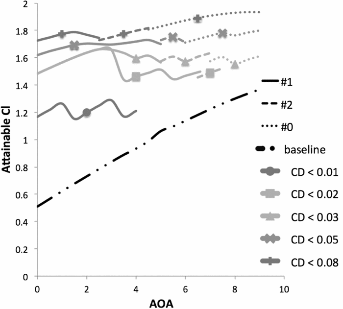
As shown in Fig. 8, where CL is plotted against angle-of-attack, strategy 1 starts to stall and lose lift earlier (at ~3° angle-of-attack), which suggests that strategy 1 can only be advantageous at low angles of attack. The maximum CL that can be achieved by the three strategies while keeping CD below a certain value is presented in Fig. 9. The baseline NACA 4418 is also plotted as a reference without the CD constraint (CD varies), It can be seen that as the angle-of-attack increases, or as the maximum attainable lift increases (at the expense of drag), the most efficient strategy changes from strategy 1 to 2, and finally to strategy 0 (hinged flap) when a very low L/D ratio is obtained. It is a sequence in which the location of maximum camber increment approaches the trailing edge and the maximum camber line curvature increases. The curves in Fig. 9 are rather zigzagged since the data points are generated from discrete data with seven trailing-edge deflection values and three strategies.
Lift curves of aerofoils with increased camber and different trailing-edge deflections, showing that the strategies with the highest efficiency in Fig. 7 lose lift at relatively low angle-of-attack.

Attainable CL by three morphing strategies with varied CD values, generated by Xfoil analysis.

The morphing aerofoils outperform the baseline, while the improvements in efficiency over hinged flaps at relatively high angles of attack (see Fig. 9) are not as significant as some previous studies have suggested. This may be because the hinged aerofoil used in the wind-tunnel tests in this research has been made as smooth as possible and the junction between wing and flap has been made airtight.
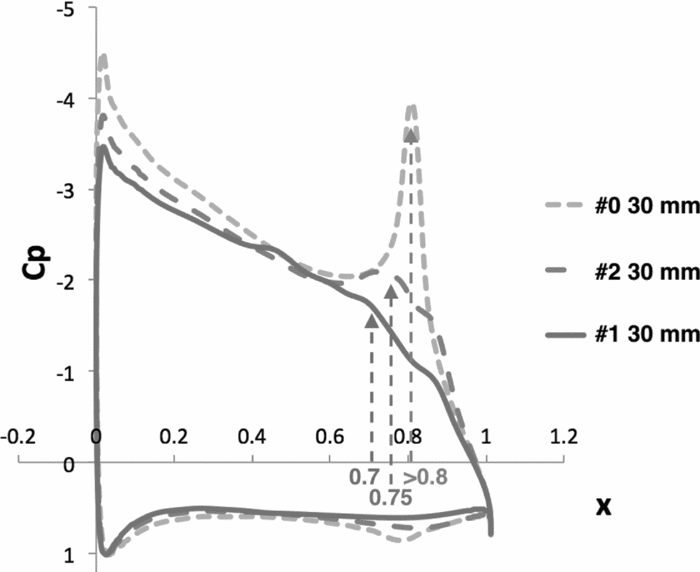
The reason why strategy 1 is efficient only at low angles of attack and suffers from low CL max, while strategy 0 (the hinged flap) is the most efficient at high angles of attack can be explained in terms of flow separation. Flow separation occurs when the speed of the boundary layer decreases to zero under an adverse pressure gradient. Figure 10 shows the pressure coefficient (CP ) across the aerofoil with unit chord length at 6° angle-of-attack using an inviscid analysis (where the flow always stays attached to show the complete pressure gradient), as well as the separation point predictions from analysis with viscous effect (where the flow separates in the trailing-edge region). Focusing on the region with x ≈ 0.6~0.8 on the upper surface where flow separation starts, strategy 1 (aerofoil with intensively increased camber near the maximum thickness) forms a relatively uniform variation in curvature, and therefore, consistently increasing adverse pressure gradient that the boundary later cannot overcome; thus, the flow separates early in this region and causes excessive drag. Strategy 0 (hinged aerofoil) forms an intensively curved surface near the hinge, where a favourable pressure gradient is formed; thus, the flow accelerates in this region and separation is delayed to the hinged point. The behaviour of strategy 2 (aerofoil with maximum camber increment near trailing edge) is between the other two.
CP -x (x = location along chord from leading edge) curve of aerofoils with 30 mm downward trailing-edge deflection via different morphing strategies generated by inviscid analysis, and flow separation point predicted by viscous analysis.

Therefore, the efficiency of different strategies can be explained: although strategy 1 (aerofoil with maximum camber increment near leading edge) is the most efficient at low angles of attack, when the location of maximum camber increment moves towards trailing edge, the flow separation points also move towards the trailing edge and lead to a higher lift and a lower drag at high angles of attack.
To be noted, the hinge pivot of strategy 0 (hinged aerofoil) is located at 75% chord length, but in Fig. 10 the hinge point is near 80% since the flap is deflected so the horizontal length of the flap is reduced. The three aerofoils have very similar chord length after morphing, and are normalised to unit chord length for illustration.
3.3.2 Results on aerofoils with a decreased camber
Aerofoils with decreased camber can generate low or negative lift for high-speed flight or manoeuvre and control pitching moment coefficients for manoeuvre or trimming.
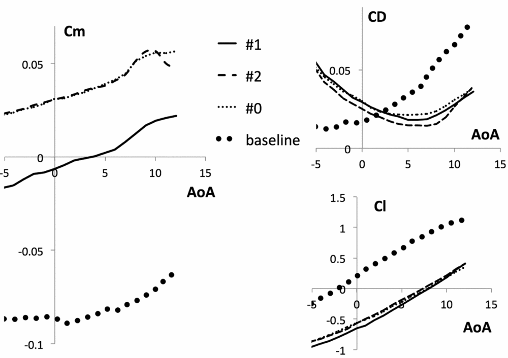
As discussed in Section 3.3.1, the key conclusions from the analysis are supported by the wind-tunnel tests, so only test data are presented in this section for a clear illustration (see Fig. 11).
Cm CD and CL versus AoA of aerofoils with decreased camber and 20 mm trailing-edge deflections, showing changes in Cm independent of Cl with little penalty in CD .

Since the reflexion of the camber line near the trailing edge lets these aerofoils generate less or negative lift in the trailing-edge region, the pitching moment Cm is increased and the increment is related to the camber line shape. Therefore, as shown by Fig. 11, strategies 1 and 2 yield different near-zero or positive Cm . Meanwhile, similar to Section 3.3.1, strategies 1 and 2 yield similar CL since they have the same trailing-edge deflection. Thus it is possible to control pitching moment while maintaining constant CL by moving the location of maximum camber change towards the trailing edge. However, a drag penalty exists according to the CD curves, but it is considerably lower than for a hinged flap.
As an example of the pitching moment control independent of CL , according the Cm curves in Fig. 11, a Cm increment of approximately 0.04 can be induced by changing the morphing strategy from strategy 1 to 2, while the CL and CD curves are barely changed.
4.0 PROTOTYPING
To further understand the behaviour of the morphing aerofoil, two prototypes are made, including a static prototype aiming to validate the loading capacity and a moveable prototype aiming to test the morphing mechanism.
The static prototype is similar to the simulation model, but with some minor differences in materials. 3D printed nylon reinforced by CFRP plates is used in some parts. Since no change is made in the compliant structures including the trusses and the upper skin and runners, which are still made of CFRP, the mechanical behaviour of the prototype should be very similar to the simulation results. In addition, all the hinges are made of composite panel with Kevlar fibre and cyanoacrylate matrix (“super glue”). The matrix along the hinge line is cracked to allow free rotation with negligible rotational resistance, and this is similar to the simulated condition. The prototype also includes a 3D printed wing box, which is overdesigned to sustain the load from the static loading test without inducing perceptible deformation. The finished morphing trailing edge weighs 0.22 N, which is close to the simulation prediction.
The static loading test is carried out with 26 N and 22 N load applied in the way identical to the simulation, which corresponds to the overall load of 70 N and 60 N across the whole aerofoil. The bonding between several hinges and upper skin fails under the load of 70 N. But under the load of 60 N, no failure is observed, and a trailing-edge deflection of 0.2 ± 0.1 mm is induced, which is close to the simulation prediction shown in Table 2. However, the out-of-plane deflection of the upper skin is larger than predicted due to excessive initial deflection induced by manufacturing defects.
The moveable prototype (Fig. 12) is similar to the static prototype, but the runner diameter is reduced from 1 mm to 0.8 mm to reduce the bending stiffness and therefore the resistance to morphing. The trailing edge and the second truss from the leading edge are each driven by one digital servo through five runners. Those runners slide through the lower joint of the truss elements while having one end fixed to the truss that is driven by it and the other end connected to a servo. Thus, the conditions are equivalent to a LUSM driven structure and the only difference is the actuators’ location. According to simple analysis, it will provide the same actuation capacity (it could support 250 N overall static load while inducing <1 mm out-of-plane deflection) and 40% of the out-of-plane loading capacity in comparison with the static prototype, while the bending resistance of rods is also reduced to 40%.
Moveable prototype. (a) Side view showing five different morphing states. (b) Oblique view showing the runners are connected to either the trailing edge or the second truss from the left.

As no off-the-shelf LUSMs can be integrated into this small demonstrator, servos are used instead of LUSMs. This also provides a practical way to drive the presented morphing structure using conventional actuators before the development of LUSM could offer a viable solution. The moveable prototype has two servos as actuators, and therefore two controlled degrees of freedom. The servos are controlled by two PWM signals generated from a STC80C516RD microcontroller. The morphed shapes are shown in Fig. 12.
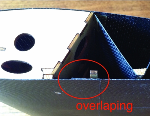
It should be noted that at this stage, neither prototypes has morphing skin on the lower surface. This will not have a significant influence on the tests since the skin has a minor effect on morphing or strength. The morphing skin will affect the flow and will require further examination in the near future. As an example, the segmented morphing lower skin shown in Fig. 13 could be introduced; it consists of two overlapping skins that are bonded to the rigid wing box and the trailing edge, respectively. The rear skin bonded to the trailing edge can slide along the runners and above the skin part that is attached to the wing box.
An example of an overlapping segmented bottom morphing skin that can be utilised to form an airtight aerofoil and transfer the aerodynamic load.

5.0 CONCLUSIONS
In this paper, a new morphing aerofoil design concept, which combines compliant runners driven by linear ultrasonic motors (LUSMs) with an innovative morphing structure with compliant composite truss, is presented. It is shown to offer fully controlled multiple degrees of freedoms that provide multiple morphing configurations. The compliant truss structure has shown satisfactory specific loading capacity in both static finite element simulation and actual static loading test. The prototype morphing trailing-edge section with a 50 mm span, a 160 mm chord-wise length and a 0.22 N weight can support a 22 N load with a trailing-edge deflection of 0.2 mm.
To validate the aerodynamic benefit of multiple degrees of freedom, the aerodynamic analysis is compared with the wind-tunnel test data. It is demonstrated that when the aerofoil camber is increased, all morphing states show a higher L/D ratio than a conventional hinged control surface at most flight conditions except at very high angles of attack. It is also shown that different morphing strategies outperform the others at different angles of attack. For example, at high angles of attack, the aerofoil aerodynamic efficiency can be further optimised by adapting morphing strategies according to current flight condition, i.e., by moving the location of the maximum camber increment along the aerofoil chord. Furthermore, the pitching moment can be controlled independently from CL and with little drag penalty; this is achieved by adapting different morphing strategies.