I. INTRODUCTION
The urgent demand for thermal spraying coating is increasing as the engineering working condition is becoming harsher. Thermal spraying coatings not only protect the integrity of the substrate and maintain the mechanical properties but also can enhance the wear and corrosion resistance of the substrate. Reference Wood1 Sprayed coatings have been applied in many different machine parts to provide wear, erosion, and corrosion protection, Reference Wang and Shui2,Reference Xiao, Lu, Zhu, Li and Wang3 such as piston ring, cylinder liners, sealing ring, etc. Reference Skopp, Kelling, Woydt and Berger4–Reference Shan, Zou, Gu, Yang, Guo, Zhao and Xiao6 However, the weak adhesion strength of the sprayed coatings due to the mechanical bond style limits their application.
Conventionally, cleaning (degreasing) and roughening are conducted on the surface before spraying coatings to ensure adequate coating/substrate adhesion which could finitely overcome the disadvantages of weak bonding strength. In the step of degreasing, chemicals or solvents are used to remove the organic and oil on the as-machined surfaces. Roughening of the surface aims to improve the mechanical anchoring of the impinging particles which build up coating. Reference Garcia-Alonso, Serres, Demian, Costil, Langlade and Coddet7 Grit blasting is a traditional pretreatment method for decades because it can modify the surface morphology by creating a random roughness, promoting the mechanical anchorage of the spraying particles. Reference Lyphout, Nylen and Ostergren8,Reference Wei, Wang, Deng and Rong9 This technique is a very effective way to improve the adhesion strength of sprayed coating. However, it has the risk of inducing microcracks on the surface. Moreover, grit blasting leads to the irregular surface topography for their stochastic nature. Reference Jiang, Wang, Lia, Li, Man, Shepard and Zhai10 Thus, an easy controlled method is necessary to replace the traditional pretreatment method.
Nowadays, tailored or designed surfaces attract an increasing attention. Pulsed laser surface texturing is a highly promising way without the disadvantages of the above methods and with a lot of advantages, such as flexibility of machining surface geometries, adaptability to different component sizes and shapes, and possibility to fully integrate the surface production to a digital environment based on CAD/CAM interfaces. Reference Maressa, Anodio, Bernasconi, Demir and Previtali11–Reference Marla, Bhandarkar and Joshi13 In recent years, more attention is captured by the improvement of the adhesion strength using different surface texturing patterns, and the parameters that affect the adhesion strength are also investigated. The adhesion strength of thermal sprayed coating and substrates strongly depends on the substrate surface: temperature, topography, and nature. Reference Fauchais, Fukumoto, Vardelle and Vardelle14,Reference Yang, Fukumoto, Yasui and Yamada15 Baburaj et al. proposed microcolumn arrays obtained by the excimer laser on commercially pure titanium. Reference Byskov-Nielsen, Holm, Hojsholt, Sa and Balling16,Reference Baburaj, Starikov, Evans, Shafeev and Bensaoula17 The results showed that the shear rupture strength of bonded specimens was 3-fold more than that of the non-treated ones. These authors attributed the outcome mainly to the geometrical changes leading to the increase of the surface area, and generation of sub-micron sized locking sites, as well as the improved wettability due to generation of titanium oxides. A. Lamraoui Reference Lamraoui, Costil, Langlade and Coddet18 processed the circle dimple on the Al substrate and altered the parameters of laser processing. They found that different laser parameters, such as the impact numbers, laser power, and focusing distance, had the influence on the dimple geometry and surrounding deposits. Meanwhile, the coating adherence produced by thermal spraying mainly depended on the geometry of the texture (depth and diameter of holes) as well as the distribution of the texture throughout the treated surface. R. Kromer et al. Reference Kromer, Costil, Cormier, Courapied, Berthe, Peyre and Boustie19 adopted two methods (tensile test and laser adhesion test) to investigate the adhesion strength, and the results of these methods were corresponding to each other. They found that the texturing patterns had a beneficial effect on the adherence due to their mechanical anchoring, which could stop crack propagation. And the textured surface with an optimized laser-hole volume allowed obtaining a much higher adhesion compared with the conventional pretreatments. Moreover, the laser-holes created barriers for crack propagation, and the crack energy release rate in the coating increased in the mixed-mode failure. However, the research on the improvement of adhesion strength with laser texturing was preliminary, and the present research only processed the circle shape dimple effect on the adhesion strength improvement. The investigations of different texturing patterns as well as the micromechanism were few. Thus, it is essential for the further research to be conducted on the adhesion strength of laser texturing.
This paper focused on the influence mechanism of three different texturing patterns (groove, square, and hexagon patterns) on the adhesion strength of sprayed coatings, which were prepared by the method of laser processing. A nickel-based coating was prepared by plasma sprayed technology on the laser textured substrate. Considering the difference of the adhesion strength, the impact factors to the adhesion strength of sprayed coatings were discussed.
II. MATERIALS AND METHODS
A. Materials and substrate pretreatment
The substrates were ASTM1045 steel, which were machined in a dimension of Φ25 × 95 mm, and the texture patterns were processed on one side of the circle bottom. The substrates were polished to the roughness less than R a = 0.4 μm to reduce the influence of surface roughness during the laser processing before the spraying processing. To investigate the influence of surface patterns on the coatings adherence, three different patterns (groove, square, and hexagon) of laser texturing were assessed by the IPG-20W fiber laser. The laser with Gaussian energy distribution produced a wave length of 1060 nm. To ensure the same depth of different patterns, the laser experiments of the groove and square pattern were conducted with a power of 14 W, a frequency of 20 Hz, 2 shots per hole, and a line speed of 600 mm/s, but for the complex hexagon pattern, a power of 12 W, a frequency of 20 Hz, 1 shots per hole, and a line speed of 4000 mm/s were used to prepare the pattern. The width of texturing was chosen as 200 μm with a distance of 100 μm.
As a reference, grit blasting was operated on the ASTM1045 steel substrates, and the final roughness was R a = 5 μm in average. The spraying process was conducted with a stand-off distance of 70 mm, a spraying angle of 75°, and a pressure of 5 bars. To ensure the fine surface state of substrate, the samples were ultrasonically cleaned with acetone after laser surface texturing and grit blasting.
B. Coating preparation
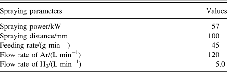
The coatings with an average thickness of 500 μm were fabricated by atmosphere plasma spraying (APS) technology. The substrates were preheated to 120 °C before spraying to alleviate the freezing phenomenon. The spraying parameters after optimization were showed in Table I. The spraying powders were Ni60 self-fluxing alloys with an average particle size of 50 μm.
Parameters of spraying.

C. Characterization of coating and texture pattern
The surface morphology and cross section morphology of different texturing patterns were characterized by scanning electron microscopy (SEM). 3D profile and 2D profiles of surface texturing were observed by the laser 3D microscopy (OLS4000, Olympus Corporation, Tokyo, Japan). The element analysis of fracture surface after tensile test was investigated by energy dispersive spectroscope (EDS). Besides, the image analysis method (IAM) was applied on the SEM graphs to calculate the contact area ratio. The adhesion test was carried out according to the standard test ASTM C633 20 by the universal extruding tester (MTS 809, MTS, Eden Prairie, Minnesota) at a constant speed 0.015 mm/s until the failure occured. The cylindrical specimens of coating were joined to a counterpart specimen with FM1000 epoxy paste, which were cured at 180 °C for 3 h. The strength value was the average from six tests under the same condition and calculated using the following equation:
 $${\rm{adhesion\ strength}} = {{{\rm{maximum\ load}}} \mathord{\left/ {\vphantom {{{\rm{maximum\ load}}} {{\rm{cross\ section\ area}}}}} \right. \kern-\nulldelimiterspace} {{\rm{cross\ section\ area}}}}\quad .$$
III. RESULTS AND DISCUSSION
A. Surface morphology of the texturing
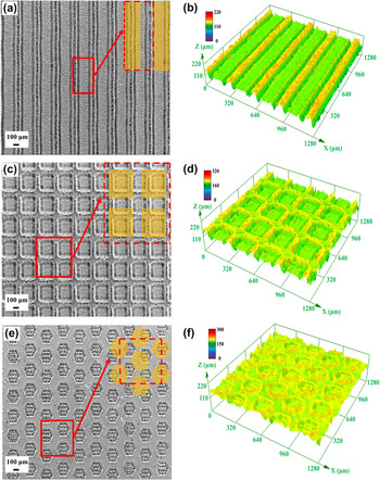
The laser–matter interaction before the particle impingements leads to the different effects at the inner and outer texture. Figs. 1(a), 1(c) and 1(e) provide the morphologies of three different texturing, respectively, showing that the patterns present regular arrangement and shapes corresponding to laser radiation features: The protrusion forms around the texturing holes due to the ejected matter; the aggregates form inside the holes for fast melting and solidification during the laser process. Besides, the area without laser radiation keeps the original morphology. The corresponding 3D structures of texturing are shown in Figs. 1(b), 1(d), and 1(f). The patterns present the morphologies accordant with the SEM pictures, and the uniform height of different texturing patterns can be confirmed. Moreover, distinct roughness at the inner dimple can be ensured with different texturing patterns due to the variant path of laser radiation depending on the texturing shape.
Surface morphology of surface texturing: (a) groove, (c) square, and (e) hexagon; 3D profile of surface texturing: (b) groove, (d) square, and (f) hexagon.

B. Cross section morphology
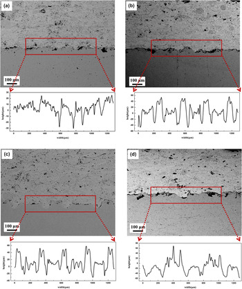
As shown in Fig. 2, cross section of grit-blasting and laser texturing patterns were observed with the 2D profile at the bottom, and the 2D profile corresponds to the tangent plane perpendicular to the texture patterns. The interface of laser treated samples present a regular pattern compared with the grit-blasting treated substrates, and the boundary lines between the substrate and coating are different with the various patterns. Meanwhile, the filling qualities of coatings are fine in the texturing holes, which can reduce the influence of air in the holes. It hence confirms that the depth is appropriate with fewer defects, and the defects are not the important factor leading to breakage after the tensile test. At the same time, it concludes that the patterns have the same depth of 60 μm accordant with the designed depth, seen from Figs. 2(b)–2(d). The aggregates around and inside the holes can be confirmed further according to the interface 2D profile.
Cross section morphology and the corresponding 2D profile of surface texturing after spraying: (a) grit-blasting, (b) groove pattern, (c) square pattern, and (d) hexagon pattern.

C. The adhesion strength and fractured morphology
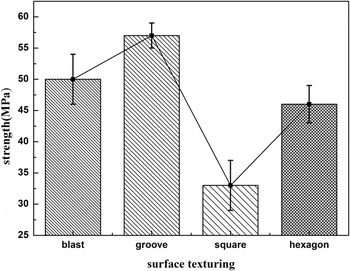
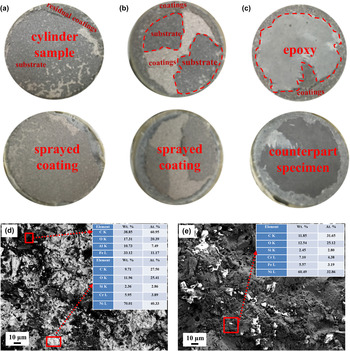
Six samples were tested with the same type of pattern, and then six values are integrated into one by taking the average value shown in Fig. 3 with the error bar. The coatings with a groove pattern show the highest adhesion strength of 58 MPa, and the grit-blasting pretreated coatings own a higher adhesion strength than the other patterns; besides, the coatings with square pattern have the lowest adhesion strength of only 33 MPa. The failure mode of coating is investigated at first, and the macro-fracture surface in this work shows three types of failure mode after adhesion test: adhesive failure [Fig. 4(a)], cohesive failure [Fig. 4(b)], and epoxy failure [Fig. 4(c)]. Especially, the upper part in Figs. 4(a)–4(c) is a cylinder sample with the texture patterns at the interface of sprayed coatings, while the bottom part is the counterpart specimen with the grit blasting treatment on the surface. From the tensile test results, the coatings with grit blasting treatment present macro-fracture morphology, as shown in Fig. 4(a), with the most coatings on the counterpart surface. And the hexagon pattern and square pattern at the interface present the same macro-fracture morphology as the grit blasting treatment. The SEM morphology of grit blasting treated coatings after the adhesion test and the corresponding EDS analysis are shown in Fig. 4(d). From the EDS results, it can be concluded that the main compositions of the dark area in the SEM are Al element and O element, and Al element is the main composition of the brown fused alumina. At the same time, Ni, Cr, and Si elements can be detected in the bright area. Thus, the fracture mode of grit blasting needs to be investigated further.
The adhesion strength of different pretreatments.

Fracture morphology: (a) adhesive failure, (b) cohesive failure, and (c) epoxy failure (failed); microscopy of samples after adhesion test: (d) grit-blasting and (e) groove pattern.

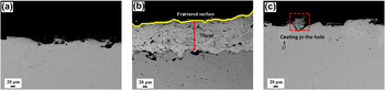
Figure 4(b) is the fracture mode of coatings with a groove pattern at the interface with the residual coatings in both the cylinder sample and counterpart specimen. The main composition of the sample is Ni60 with the appearance of Ni element through the EDS analysis [Fig. 4(e)]. However, the fracture mode needs to be investigated further with the appearance of Fe element. Thus, further analysis is about the cross section morphology of failure coatings after the tensile test. Figure 5(a) is the cross section morphology of grit-blasting treated coating after adhesion test, presenting the processed substrate without residual coatings with a certain thickness in the hole. It confirms the interface breaking type of grit-blasting treated coating during the tensile test. Particularly, Fig. 5(b) shows the cross section morphology of failure coating with a groove pattern, and the residual 70 μm thick sprayed coating can be confirmed, while the thickness of as-sprayed coatings is 500 μm. In short, the strength of coating with a groove pattern mainly depends on the cohesion of Ni60 sprayed coatings, proving that the interface adhesion strength of coatings with a groove pattern is higher than that of the tested 58 MPa. Thus, the failure mode of sprayed coatings with a groove pattern in the interface is cohesive failure [Fig. 4(b)]. Therefore, the epoxy failure mode in Fig. 4(c) is indicated to be invalid results due to the cohesive 70 MPa strength of glue which is higher than the cohesive strength of chosen coatings (58 MPa). The appearance of invalid results is that the center lines of test samples and the counterpart specimen are lack of alignment. The sample in Fig. 4(c) is the epoxy failure mode with a square pattern in the interface with the epoxy in the cylinder sample.
Cross section of different pretreatment after adhesion test: (a) grit-blasting, (b) groove pattern, and (c) hexagon pattern.

Moreover, the cross section morphologies of coatings with square pattern and hexagon patterns after the tensile test are the same with grit-blasting treated coatings without the appearance of thick residual coatings at the interface. Nonetheless, although the fracture mode is adhesion, hexagon texturing holes still contain coatings as shown in Fig. 5(c), which is attributed to the strong anchored ability of dimples. The fracture surface of coating with a square pattern is similar to the grit-blasting treated interface without certain thickness coatings like the groove pattern fracture interface or coatings in dimples like the hexagon pattern fracture interface. To investigate the mechanism of the bonding of coatings, the analyses are carried out in the following.
D. Discussion
1. Contact area ratio
The functions of pretreatment methods, such as grit-blasting, laser texturing, and shot-blasting, aim at increasing the contact area at the interface of coatings and substrates, which is beneficial to the stress release, minimizing the stress concentration and thus degrading the emergence of cracks. Reference Kromer, Cormier and Costil21 Following two steps, image pro plus was used to investigate the real contact area between coatings and substrates. The calculation of square pattern is taken as the sample because it is inhomogeneously distributed in the horizontal direction leading to the complicated process:
-
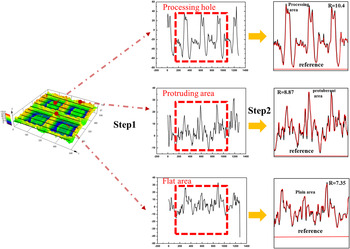
(i) A 3D morphology image of square pattern was obtained by the 3D surface profilometer to investigate the morphology properties. The results show that the roughness of the square texturing is uneven along the Y direction, so ten areas including both the protruding area and the relative flat area were chosen to acquire the 2D profile, as shown in Fig. 6. Then the 2D profile images were cut into the same width. Meanwhile, the 2D profile images have the obvious contract in colors, and the threshold treatment of images was thus not essential.
-
(ii) After the previous jobs, the image pro plus was used to analyze the images. As the images acquired in the first step has the white background and the black line, the autotrack was executable, and the acquired tail is in accordance with the cross section line of coatings/substrate interface. After tracing the line in the 2D profile, the length of the line can be accessed directly, as shown in Fig. 6. Ten values were integrated into one by taking the average value to ensure the accuracy of data.
Calculation process of additional contact area.

The width value of the image acquired in the first step is a constant. If the substrate is not pretreated, the width is trace of the substrate without roughness. Similarly, the width value can be acquired by the image pro plus, and the additional line length of the texturing can be calculated by the ratio of the texturing length to the length of substrate without pretreatment, which is defined as R 1, shown in Eq. (1),
 $${R_1} = {{L\left( {{\rm{length\ of\ texturing}}} \right)} \over {L\left( {{\rm{length\ of\ substrate}}} \right)}}\quad .$$
Thus, the additional line length was acquired. The texturing length of the Z axis is defined as D, and the contact area is L multiplied D. The contact area ratio R is shown in Eq. (2),
 $$R = {{L\left( {{\rm{length\ of\ texturing}}} \right) \times D} \over {L\left( {{\rm{length\ of\ substrate}}} \right) \times D}} = {R_1}\,\quad.$$
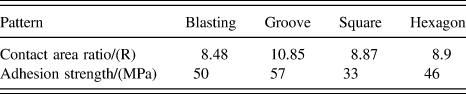
After calculating, ten values of each texturing pattern are acquired, and the average value of R is calculated. The contact area ratio of the blasting pattern, groove pattern, square pattern, and hexagon pattern is as shown in Table II.
Contact area ratio with different texture patterns.

The groove pattern has the highest R and the deserved adhesion strength of coatings as shown in Table II. However, the square pattern and the hexagon pattern have the higher R value but the lower coatings adhesion strength compared to the grit-blasting treated coatings, which is not in accordance with the previous knowledge. Reference Kromer, Costil, Cormier, Courapied, Berthe, Peyre and Boustie19,Reference Kromer, Cormier and Costil21 Not only that, the value of R is similar between the square pattern and the hexagon pattern, while the adhesion strength of coatings presents great divergence. Thus, some other impact factors should be considered. In the followings, the texturing density and the adherence mechanism are discussed further.
2. Surface texturing density
The texturing density is the key factor to influence the adhesion strength. Although the surface texturing increases the contact area of sprayed coatings, the area between the texturing is plain where the fracture is easy to start, as shown in Fig. 1. The smooth plain area is detrimental to the mechanical locking of sprayed particles, and the vast texturing density means the less plain area. The smallest geometric cell was chosen to calculate the texturing density. In other words, after choosing the reasonable geometric cell, the area percentage of texturing could be calculated, and then the density (d), as shown in Eq. (3),
 $$d = {{S\left( {{\rm{texturing}}} \right)} \over {S({\rm{geometric\ cell}})}} \times 100\% \,\quad.$$
Figures 1(a), 1(c) and 1(e) show the schematic diagrams of the surface texturing geometric cell with groove, square, and hexagon patterns, separately. The schematic diagrams are inserted into the SEM photos of texturing, and the dashed circle indicates the area of smallest geometric cell. Obviously, the area indicated by a dashed circle has the repeat property, and it can approximately replace the texturing density. Then the density is calculated based on Eq. (3).
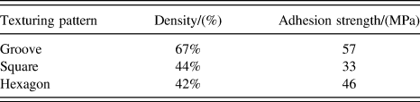
The density of different texturing patterns is obtained through calculating, as shown in Table III. By comparing with the results, the adhesion strength of coatings with a groove pattern is the highest, and the contact area of groove pattern is the largest. The contact area ratio of grit-blasting treatment is lower than the square pattern and the hexagon pattern processed by the laser method, while the density of grit blasting is nearly 100% without the obvious plain area. Thus, the adhesion strength of sprayed coating after grit blasting is higher. However, the square pattern and the hexagon pattern have the similar contact area ratio and density, but the adhesion strength of coatings has the great difference. To investigate the mechanism further, the adherence mechanism is discussed.
Density of different texturing patterns.

3. Adherence mechanism
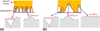
As we know, the adherence mechanism of sprayed coatings is a mechanical bond, and the mechanical bond of melted particles on the rough surface can be divided into five styles Reference Amada and Hirose22,Reference Amada and Hirose23 : embedding, anchoring, holding-on, spreading, and mixture of several styles. According to the characters of the grit blasting treatment and surface texturing, the illustration of mechanical bond styles of sprayed coating on different rough surfaces is shown in Fig. 7.
Adherence mechanism of blasting and surface texturing: (a) grit blasting treatment and (b) surface texturing.

Corresponding to the mechanical bond styles, the grit blasting pretreatment mainly presents the embedding and holding-on styles, while the surface texturing treatment is the mixture style of spreading, holding-on, and embedding. And the spreading style is the weakest mechanical bond, which limits the further improvement of adhesion strength of sprayed coatings. Although the residual coating is still in the hole, the weak bonding of spreading area around the hole leads coating to break, as shown in Fig. 5(c). It is the reason for that although the R of surface texturing is higher than that of the blasting treatment, the adhesion strength is still lower. Moreover, the adhesion mechanism is the same and the R value is similar to the square pattern and the hexagon pattern, and the difference of adhesion strength is due to the microstructure of laser surface texturing.
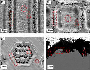
The microstructure of different surface texturing is shown in Fig. 8. The rectangle, circle, and triangle represent the holding-on, spreading, and embedding area, separately. Figure 8(d) is the cross section morphology of hexagon pattern, which confirms the holding-on, spreading, and embedding area of texture patterns. Reference Amada and Hirose22 Compared to the hexagon pattern, the square pattern has more spreading area due to its microstructure features inside the dimple which is the reason why the square pattern fracture interface does not present the morphology of coatings in the dimple like hexagon pattern [Fig. 5(c)]. Although the contact area ratio is not the lowest, the square pattern which possesses lower density and weaker mechanical bond has the lowest adhesion strength. The results show that the adhesion strength is not only influenced by the contact area ratio and the density but also varied along with the microstructure deviation of texturing.
Different mechanical adhesion types in the microstructure of texturing: (a) groove pattern, (b) square pattern, (c) hexagon pattern, and (d) cross section of hexagon pattern.

IV. CONCLUSIONS
Three different texturing patterns were prepared by laser processing, and the adhesion strength was tested. Compared to the grit blasting treatment, the texturing patterns present the different mechanical bond styles. According to the results of experiments, several conclusions were acquired as follows:
-
(1) The texturing processed by the laser radiation present the following features: the area between the texturing is plain; the protrusion forms around the texturing holes due to the ejected matter; meanwhile, the aggregates form inside the hole for the fast melting and solidification during the laser process. The different pattern leads to the variant contact area ratio at the coatings/substrate interface, which is the main reason leading to the different adhesion strength of sprayed coatings.
-
(2) The coatings with a groove pattern own the highest 58 MPa adhesion strength test value among all the tensile test results, and the fracture mode is cohesive fracture. Compared to the grit blasting treatment, the contact area ratio with a groove pattern increases 1.28 times. Meanwhile, the groove pattern own bigger density and less plain area compared with other patterns, which leads to the highest adhesion strength for the groove pattern together with the contact area ratio.
-
(3) The plain area between textures is adverse to the improvement of adhesion strength of spraying coatings with texture at the interface. In contrast to the grit blasting treatment, the square and the hexagon patterns get lower adhesion strength. That is because the grit treated substrates cover the whole substrate area, while the laser processed substrates have to bear the property prone to fracture resulted from plain area.
-
(4) The laser treated square pattern and hexagon pattern process the similar contact area ratio and density, but the adhesion strength is different due to the bonding style and microstructure. Compared to square pattern, the hexagon patterns have less spreading area inside the dimple which limits the improvement of adhesion strength of spraying coatings; thus, the adhesion strength of coatings with a hexagon pattern is higher than that of a square pattern. Furthermore, the shape and parameters of surface texturing should be optimized according to the impact factors to adhesion strength.
ACKNOWLEDGMENT
The paper was financially supported by NSFC (51475473), NSFC (51535011), 973 program (61328304), and Fundamental Research Funds for the Central Universities (No. HEUCF).