Introduction
Military radars are mostly employed for weapon system tracking and detecting aircraft and missiles [Reference Josefsson and Persson1, Reference Lanzagorta2]. The X-band covers the radar frequencies used in missile guidance because of the larger target size. The track-while-scan ability of most present-day radars empowers them to work both as fire-control radar and search radar at the same time. Multitudinous radar beams generated simultaneously by the phased array antenna system is used for track-while-scan radars. Phased array antenna systems used in missile radars require antenna arrays with compact antenna elements. The objective is to reduce the size of the antenna element without compromising gain. Aperture-coupled antennas are brilliant contenders for phased array applications because of their advantage of being low-profile with high gain and low sidelobe level. The high gain and low sidelobe level is due to the isolation of the feed circuit from the radiating element through the ground plane [Reference Pozar3]. Using two different substrates is advantageous as we can select the substrates in such a way that a substrate with lower dielectric constant is used for radiating element and that with higher dielectric constant is used for the feed circuits.
Compactness along with gain enhancement can be achieved in aperture-coupled antennas by using fractal slot and defective ground plane [Reference Mishra, Sahoo, Hota and Mangaraj4], stacked patch [Reference Sethi, AlShareef, Ashraf, Behairy and Alshebeili5–Reference Minz, Kang and Park7], substrate integrated waveguide [Reference Zhong, Hong and Zhou8, Reference Foudazi, Roth, Ghasr and Zoughi9], by using superstrate [Reference Meng and Sharma10, Reference Dash, Cheng and Khan11], and by various other technologies [Reference Jiang, Li and Xue12–Reference Le Thi, Ta, Nguyen, Nguyen and Dao–Ngoc19]. All the above works of literature have used a single or dual rectangular slot, H-shaped slot, I-shaped slot, and cross-shaped slot. Hence, it is evident from the literature that the shape and size of the slot play a key role in determining the characteristics of an aperture-coupled microstrip patch antenna (ACMPA). There are reported works [Reference Pozar and Targonski20, Reference Rathi, Kumar and Ray21], which state the role of electromagnetic coupling enhancement between the feedline and the patch with the change in aperture shape. However, effect of aperture shape and size on input impedance and antenna gain per unit aperture area is not addressed. This paper addresses the above by developing a compact antenna. Gain enhancement on the compact structure is achieved by enhancing the electromagnetic coupling between the feedline and the radiating element by judiciously choosing the slot shape with more degree of freedom for parametric analysis. The effect on slot shape on input impedance and antenna gain per unit aperture area is also analyzed.
A compact ACMPA with a modified hourglass-shaped aperture which provides enhanced coupling compared to the conventional coupling slots is proposed. The proposed antenna suits well as a unit cell for phased array applications. This paper is set out in the following way. The design of ACMPA with different conventional aperture shapes like rectangular, H-shaped, bowtie, hourglass, along with the proposed modified hourglass-shape are depicted in Section “Design and methodology of ACMPA.” The methodology employed for size reduction has also been discussed here. Parametric study and the corresponding simulated results are highlighted in Section “Parametric studies.” The effect of different aperture shapes and sizes on the antenna radiation pattern are also portrayed in this section. Equivalent circuit model of the proposed antenna is prepared and matched by |S 11| in this section. The proposed antenna with modified hourglass-shaped aperture is fabricated and the comparison of results of the proposed antenna with reported literature are also given in this section. Ultimately, the final section concludes the article.
Design and methodology of ACMPA
The proposed antenna is designed for the operating frequency of 10.5 GHz, which is used for X-band phased array radar applications [Reference Josefsson and Persson1]. In this proposed antenna, a circular patch is being fed by a stepped feedline through a slotted ground plane. The antenna operates in its dominant TM 110 mode. The radiating circular patch is supported by a Rogers RT/duroid 5880 substrate with a relative permittivity of 2.2 ($\epsilon _{rp}$ ); tanδ of 0.0009, and a thickness of 0.787 mm (h p). The feed is supported by a Rogers RT/duroid 6010 substrate with a relative permittivity of 10.2 ($\epsilon _{rf}$
 ); tanδ of 0.0023, and a thickness of 0.254 mm (h f). A conducting ground plane with an aperture is placed in between the two substrates. The initial value of patch radius for the center frequency of the antenna operating at its dominant mode is found using

where

as 5.1 mm [Reference Balanis22]. The antenna resonant frequency varies with a change in the radius of the patch.
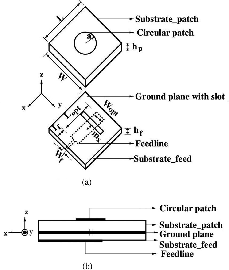
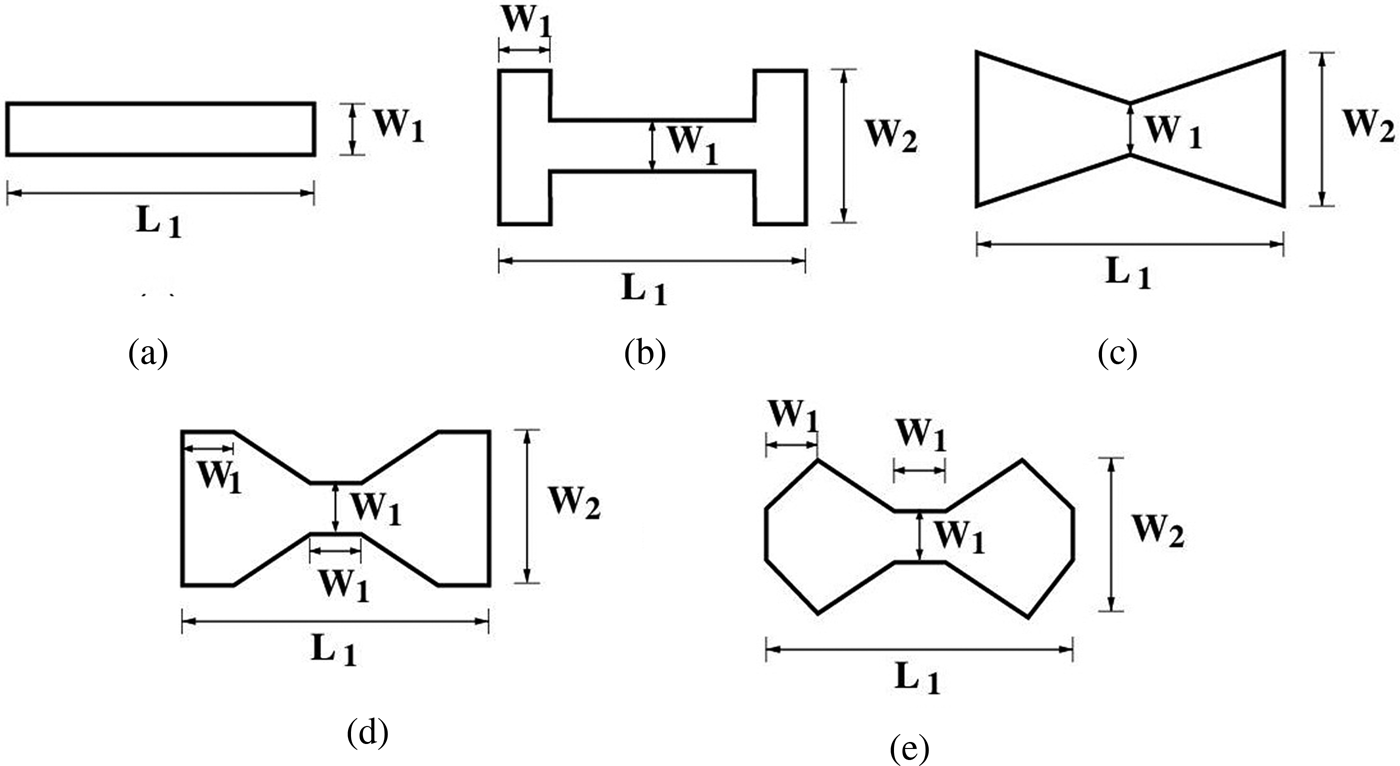
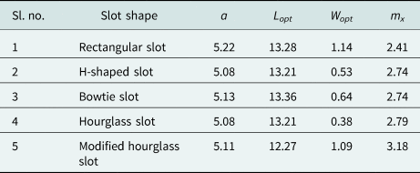
It is to be noted that an impedance transformer of dimension L opt × W opt is used for better impedance matching and this transformer has a different dimension from the feedline width W f (Fig. 1). m x is the slot offset from the center of the patch along the length of the antenna structure. Parametric studies is performed on m x for a further impedance matching. Figure 1 shows the exploded view and side view of ACMPA. Initially, a rectangular slot with dimensions W 1 × L 1 is taken. Final slot dimensions are obtained by parametric studies for better impedance matching, keeping a constant slot length of 2.88 mm. Keeping all other parameters constant, the same antenna is redesigned with different slot shapes like H-shape, bowtie, hourglass, and modified hourglass. Table 1 gives the final values of the antenna parameters for desired operating frequency and better impedance bandwidth obtained by parametric studies. Figure 2 shows the dimensions of the different slot shapes.
ACMPA. (a) Exploded view. (b) Side view [W = L = 4 × a)].

Different slot shapes. (a) Rectangular slot. (b) H-shaped slot. (c) Bowtie slot. (d) Hourglass slot. (e) Modified hourglass slot [W 2 = 1.43 mm, L 1 = 2.86 mm, and W 1 = 0.29 mm (for rectangular, H-shaped, bowtie, and hourglass slot) and 0.48 mm (for modified hourglass slot)].

Final dimensions of antenna with different slot shapes obtained by parametric studies.

All dimensions are in mm.
In the aperture-coupled antenna design, as the ground plane separates the radiating patch and the feedline, the stray back radiation from the feedline is reduced. The same can also be reduced by printing the feed circuit on a substrate with higher dielectric constant. Also, the excitation of surface waves produced by the substrate with higher dielectric constant lessens the stray back radiation [Reference Adrian and Schaubert23]. Similarly, the ability of the patch to radiate more power can be enhanced by printing the patch on a substrate with low dielectric constant. The feed substrate with high relative permittivity achieves size reduction in the feed circuit too. In contrast, the patch substrate with low relative permittivity radiates more power, provides enhanced bandwidth, and reduces scan blindness. This flexibility enables the proposed design to be used for phased array application. This design eliminates the use of vias for back radiation reduction, thereby eliminating the problems created by vias in reliable fabrication and the introduction of additional self-reactance into the structure. The frequency of resonance is basically controlled by the dimension of the radiating circular patch. Slot lengths determine the measure of coupling, while the lengths of the open-ended feedline stub changes in accordance with attaining the ideal reactance. Furthermore, the slot's lateral shift in the non-resonance direction affects the input impedance by little, given the whole slot under the patch.
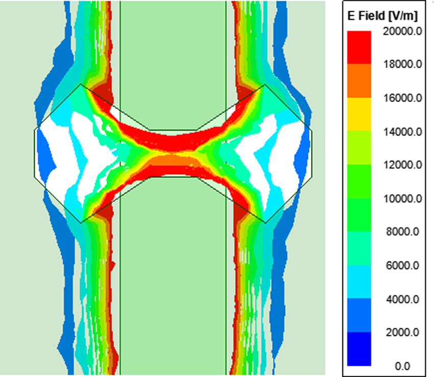
In comparison of rectangular slot and H-shaped slot, there is an increase in effective area in H-shaped slot due to the additional dimension of W 2 at the ends of H-shaped slot [Reference Pozar and Targonski20]. The additional loading at the slot end makes the electric field distribution more uniform in the H-shaped slot compared to that of the rectangular one. Since the field distributions are maximum at the slot's center, maximum coupling to the feedline is attained when the feed is positioned in the middle of the slot, and coupling will be diminished as the feed is pushed toward the slot edge. The same concept is applicable for other types of slots with loading at the end like bowtie, hourglass, and modified hourglass. Hence, in this analysis of different shapes of aperture, feed is always placed at the middle of the slot. Figure 3 shows the electric field distribution in modified hourglass slot ACMPA, which is maximum at the center of the slot and reduces gradually towards the slot end. Also, the electromagnetic wave reflections are reduced in case of modified hourglass slots as there is an uniform transition in width from the loaded end to the center of the slot, variation of field distribution from center to the edge of the slot is very smooth compared to the conventional rectangular slot. Among the other shapes, the reflections produced by the sharp discontinuities are minimal in modified hourglass slot ACMPA.
E-field distribution in modified hourglass-shaped aperture.

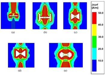
Hence, in a ground plane with a modified hourglass slot ACMPA, surface current distribution is more concentrated around the slot compared to conventional rectangular slot (Fig. 4). Hence, for those applications where the feedline should be moved from the center of the slot in the non-resonance direction, the proposed modified hourglass slot, will cause a little decrease in coupling, when contrasted with rectangular one, on the ground that its surface current distribution is more uniform around the slot.
Surface current distribution on the ground plane with different types of aperture. (a) Rectangular slot. (b) H-shaped slot. (c) Bowtie slot. (d) Hourglass slot. (e) Modified hourglass slot.

The explanation behind improved coupling given by modified hourglass-shaped slots is that by removing the sharp discontinuities, the upsides of both the H-shape and bowtie shape have been consolidated. Removal of sharp discontinuities in the structure makes the surface current distribution around it more concentrated and uniform. The concentrated current distribution around the slot achieves enhanced coupling. Identically, for a constant slot width/length ratio and for a given slot offset, a smaller modified hourglass aperture will give a better electromagnetic coupling compared to conventional aperture shapes which ultimately leads to a compact antenna design. The open circuited stub type feedline permits the coupling of microwave power from the feedline to the patch through the small slot under the patch. The slot size, position, shape, and stub length governs the input impedance of the structure. Since various slots have diverse coupling, it is a judicious choice to utilize a slot shape which offers good coupling for a small aperture area and reduced back radiation. Unlike other slot shapes modified hourglass aperture offers more degree of freedom for impedance matching parameters.
Parametric studies
Effect of slot shape on input impedance
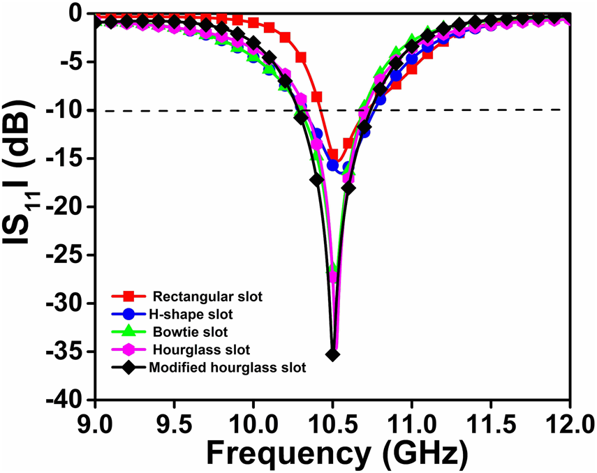
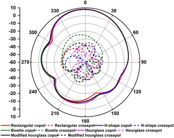
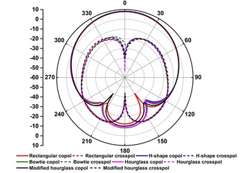
A parametric analysis is essential to understand the effect of various design parameters on antenna's performance. To notice the impact of various slot shapes on the input impedance, numerous ACMPAs are designed using ANSYS electronics desktop. Comparison of |S 11| values of antennas with different slot shapes is given in Fig. 5. For a fixed aperture length, the increased |S 11| value of modified hourglass-shaped aperture shows that modified hourglass ACMPA is giving a improved impedance matching compared to other slot shapes which is evident from the minimum |S 11| at resonant frequency. The co-pol and cross-pol radiation patterns at x–z plane for various slot shapes are given in Fig. 6. Though the cross-pol level of modified hourglass slot (−40 dB) is better than the rectangular slot, bowtie slot, H-shaped slot, it is more than the hourglass-shaped aperture (−60 dB). Since −40 dB cross-pol level is good enough, this difference is neglected. The co-pol and cross-pol radiation patterns at y–z plane for various slot shapes are given in Fig. 7.
Plot of |S 11| parameter for various slot shapes.

x–z plane radiation pattern at 10.5 GHz for various slot shapes.

y–z plane radiation pattern at 10.5 GHz for various slot shapes.

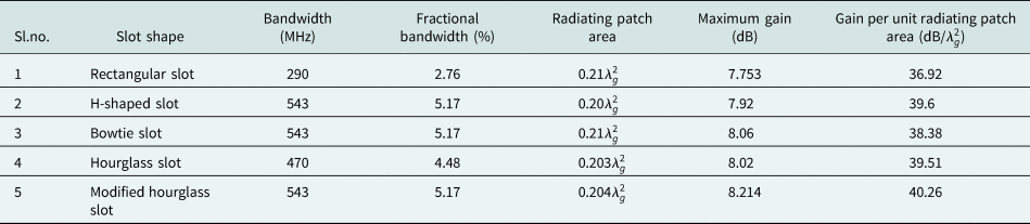
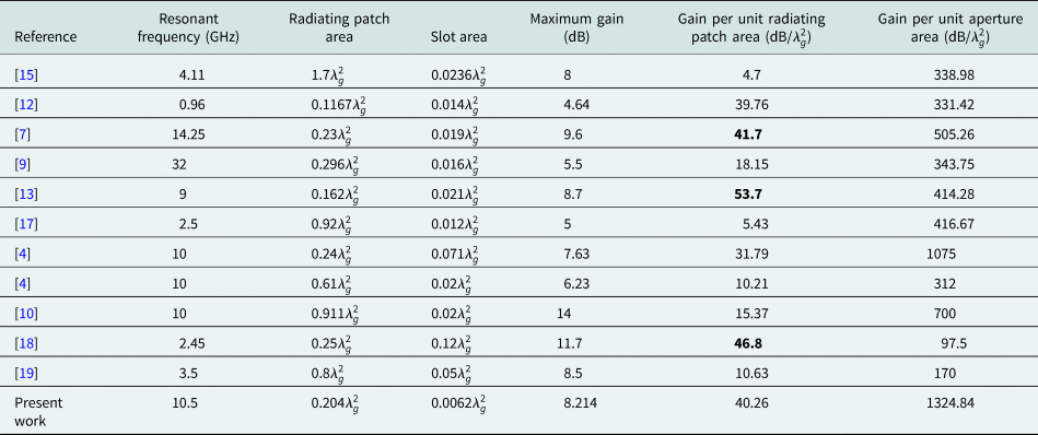
It shows that the proposed design gives improved co-pol and cross-pol at both x–z and y–z planes. Table 2 gives the comparison of simulated bandwidth and gain of antennas with different slot shapes. It reveals that the proposed design is giving a −10 dB bandwidth of 543 MHz with a start and stop frequencies of 10.377 and 10.92 GHz, respectively. It gives a fractional bandwidth of 5.17$\%$ , maximum gain of 8.214 dBi and a better gain per unit radiating patch area of 40.26 (dB/$\lambda _{g}^2$
 ) compared to other designs. It verifies that the modified hourglass slot is giving maximum gain at center frequency and also maximum gain per unit radiating patch area compared to other types of slots.
Comparison of simulated bandwidth and gain of antennas with different slot shapes

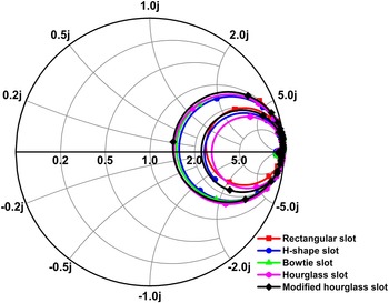
The ACMPA's input impedance is corresponding to the electromagnetic coupling through the slot from the feedline to the patch, however there is no straightforward reliance between these two numbers [Reference Pozar and Targonski20]. Accordingly, various distinctive slots like rectangular slot, H-shaped slot, bowtie slot, hourglass slot, and modified hourglass slot are used in the same antenna design and are analyzed. Rectangular slot with a length of 2.88 mm and a width of 0.29 mm is mentioned in the analysis. The final dimensions of slot width of the H-shaped slot, bowtie slot, hourglass slot, and modified hourglass slot are obtained by parametric analysis, keeping a fixed slot length of 2.88 mm. It is preferable to choose an aperture shape that would offer improved coupling for a fixed slot length. The impedance loci in Fig. 8 for different slot shapes retaining the slot length reveals that the rectangular slot has limited coupling, which can be viewed by small locus area and the far position of the locus from the center of the Smith chart. For the same length, the coupling increases for H-shaped aperture, bowtie aperture, hourglass aperture, and modified hourglass aperture. Modified hourglass slot has a bigger input impedance locus closer to the center of the Smith chart inferring improved coupling than the other types of slots. For the same radiating element measurements, if the proposed modified hourglass-shaped slot is utilized in the antenna, maximum coupling is attained which is evident from the bigger input impedance locus, as shown in Fig. 8.
z locus Smith chart for slot shape analysis.

Effect of slot length on input impedance
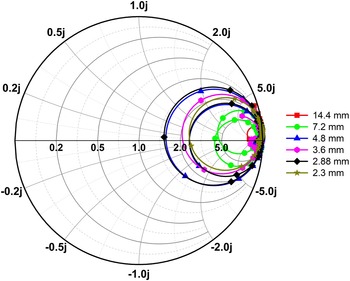
The effect of slot length on the impedance locus is given in Fig. 9. Suppose the slot lengths are taken as 14.4 mm, 14.4/2 (7.2 mm), 14.4/3 (4.8 mm), 14.4/4 (3.6 mm), 14.4/5 (2.88 mm) till 14.4/6 (2.3 mm), keeping the slot width/length ratio as constant at 1:6 in the proposed modified hourglass slot ACMPA. When the slot length is decreased from 14.4 to 2.3 mm, size of the impedance locus increases, enhancing the coupling as the circle becomes more closer to the center of the Smith chart with a decrease in slot length from 14.4 to 2.88 mm. But locus corresponding to the length 2.3 mm reveals that it is smaller than the z locus of 2.88 mm. However, because of fabrication ease 2.88 mm slot length is considered to give enhanced electromagnetic coupling from the feedline to the radiating patch than other lengths.
z locus Smith chart for slot length analysis.

Equivalent circuit model
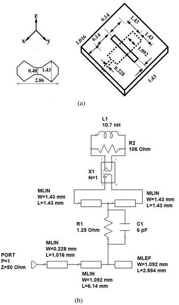
To physically interpret the proposed modified hourglass slot ACMPA, an equivalent circuit model of the same is prepared and is shown in Fig. 10 along with the feed and aperture dimensions. The equivalent circuit model is designed in the AWR design environment. The length of the feedline is divided into three sections. The feedline from SMA connector end whose width corresponds to 50 Ω impedance is the first section and the feedline section before the aperture whose width is tuned for better impedance matching is the second section. The first two sections of feedline are represented as microstrip lines [Reference Garg, Bhartia, Bahl and Ittipiboon24, Reference Soh, Rahim, Asrokin and Aziz25] and their dimensions are same as that of feedline dimensions in geometrical design.
Equivalent circuit model of the proposed antenna. (a) Feed and aperture dimensions in mm. (b) Schematic model.

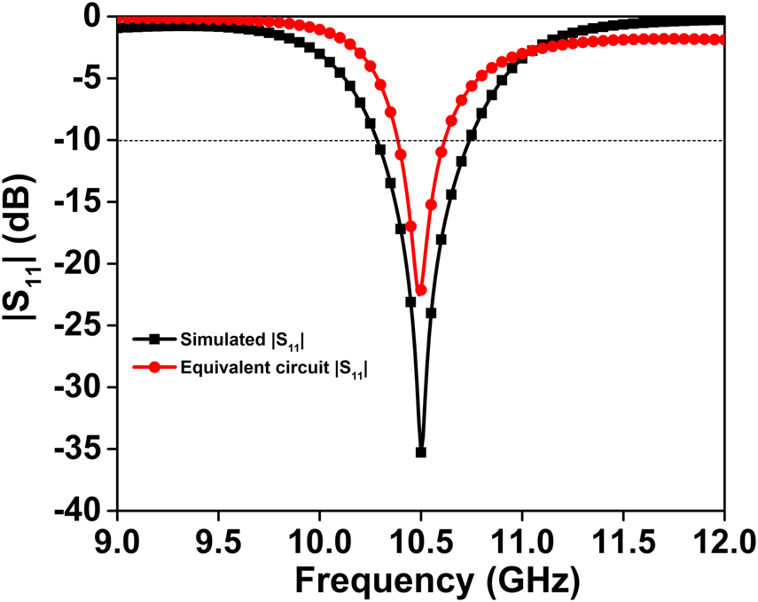
The section of the feedline after the aperture is the open-ended stub and is represented as open-ended microstrip line. The open-ended stub length is tuned for better impedance matching; however, the width is maintained constant. The patch is denoted as parallel RL circuit (R2, L1). The electromagnetic power transmission from feedline to the ground plane aperture is denoted by a parallel RC circuit (R2, C1). The aperture is divided along with its width and is represented by two microstrip lines [Reference Soh, Rahim, Asrokin and Aziz25]. The aperture length and width are chosen same as that of the geometrical design (Fig. 10). A transformer with equal turns on both sides is placed between the slot and patch to denote the coupling. The fine-tuned values of R1, C1, R2, and L1 are found to be 1.25 Ω, 6 pF, 106 Ω, 10.7 nH, respectively. The equivalent circuit model is validated by matching the |S 11| plot of the circuit model with that of the simulated |S 11| plot at the resonant frequency of 10.5 GHz. The matched |S 11| plot is shown in Fig. 11.
Matched |S 11| plot of equivalent circuit model with simulation.

Results and discussion
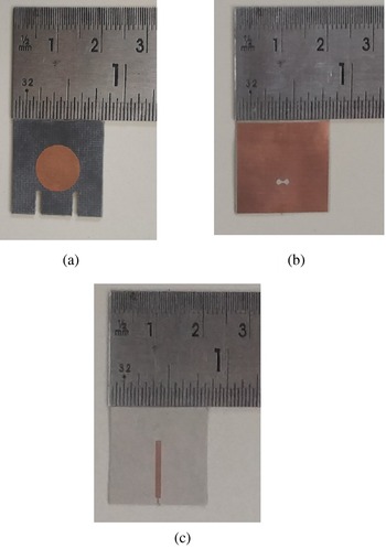
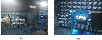
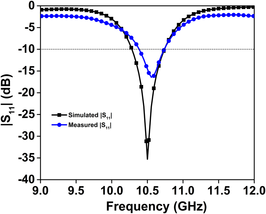
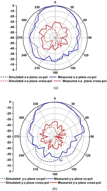
The proposed modified hourglass ACMPA prototype is fabricated to validate the design and is displayed in Fig. 12. |S 11| is measured using the Keysights E5071C ENA vector network analyzer. Testing of the fabricated antenna in an anechoic chamber is set out (Fig. 13). Figure 14 shows the simulated and measured |S 11| plot. The measured |S 11| plot resonates at 10.55 GHz with a slight difference from the simulated one. In the |S 11| plot, −10 dB start and stop frequencies are 10.425 and 10.9 GHz, respectively. Also, the −10 dB bandwidth and fractional bandwidth are 475 MHz and 4.5$\%$ , respectively, for the resonant frequency of 10.55 GHz. Figure 15 shows the normalized radiation patterns (measured and simulated) of the modified hourglass slot ACMPA in the x–z plane and y–z plane at 10.5 GHz.
Fabricated antenna. (a) Substrate with patch. (b) Ground plane with slot. (c) Substrate with feedline.

Measurement setup. (a) Test setup. (b) Antenna under test.

Measured and simulated |S 11| plot.

Normalized radiation patterns at 10.5 GHz (simulated and measured). (a) x–z plane. (b) y–z plane.

The measured gain at the desired frequency is found to be 7.2 dBi. Figures 14 and 15 confirm that the simulated results are aligned with the measured results. The malalignment in the setting up of multiple substrates is the reason for the slight mismatch between simulated and measured results. The various parameters of the fabricated prototype are compared with the reported works in Table 3. Though literature [Reference Minz, Kang and Park7, Reference Yazdanpanah and Zehforoosh13, Reference Tripathi, Pathak and Parida18] are giving better gain per unit radiating patch area, their gain per unit aperture area is much less than the proposed antenna. The proposed modified hourglass ACMPA gives a better gain per unit aperture area and better gain per unit radiating patch area compared with the antenna in the reported works.
Comparison of various parameters of the proposed antenna with reported works

Conclusion
A compact aperture-coupled microstrip patch antenna at frequency of 10.5 GHz has been presented. The antenna is designed with a two layer substrate, a circular patch, and an aperture-coupled feedline. Effect of aperture shape on S-parameter, radiation patterns, input impedance, and gain of the antenna has been analyzed using antennas designed with different slot shapes like rectangular, H-shape, bowtie, hourglass, and modified hourglass. For a uniform slot length, the modified hourglass slot gives the improved coupling compared to that of rectangular slot, H-shaped slot, bowtie slot, and hourglass slot. Modified hourglass ACMPA with different slot lengths are designed keeping a constant slot width to length ratio of 1:6. The results confer that the undesired back radiation from the slot is decreased because a smaller slot can reveal an enhanced coupling. For the same slot width upon length ratio, 2.88 mm slot length gives a good input impedance at resonance. The final proposed antenna is modified hourglass ACMPA with the slot length of 2.88 mm with the antenna volume of 1.02λ g × 1.02λ g × 0.052λ g and an aperture area of $0.0062\lambda _g ^2$ . A gain of 8.214 dBi is obtained for the final design. A gain per unit radiating patch area of 40.26 dB/$\lambda _g ^2$
 and gain per unit aperture area of 1324.84 dB/$\lambda _g ^2$
 is obtained for the proposed antenna. The fabricated and measured final antenna gives a measured gain of 7.2 dBi. Because of the compact and low-profile antenna structure, the proposed antenna is well suited for the unit cell of phased array antennas used in missile radar application.
Acknowledgements
This work was supported by Women Scientist Scheme-A of Department of Science and Technology, Government of India with the project ID: SR/WOS-A/ET-88/2017.
Conflict of interest
The authors declare none.
 P. Priyalatha received her B.E. from Madurai Kamaraj University, Madurai, Tamilnadu in 2002 and M.Tech. from Bharathidasan University, Trichy, Tamilnadu in 2004. She has received a Women Scientist fellowship (WOS-A) from DST, Goverment of India in 2020. Currently, she is a research scholar in the Department of Electrical and Electronics Engineering, Birla Institute of Technology and Science, Pilani, Hyderabad campus, India. Her research areas are phased array antennas, aperture-coupled planar antenna arrays, and substrate integrated waveguide-based power dividers. She is a student member of IEEE and a life member of ISTE.
 Runa Kumari received her both B.E. and M.Tech. from the Biju Patnaik University of Technology, Odisha in 2003 and 2008, respectively, and Ph.D. from the National Institute of Technology, Rourkela, in 2014. She is presently working as an associate professor at the Department of Electrical and Electronics Engineering, Birla Institute of Technology and Science, Pilani, Hyderabad campus, India. Her current research interest includes log-periodic antennas, dielectric resonator antennas, planar antennas, reconfigurable planar antennas, and metamaterial. Dr. Kumari is a senior member of IEEE.
 Sourav Nandi received his B.Tech. from the West Bengal University of Technology in 2010 and M.Tech. from the University of Kalyani in 2013. He received his Ph.D. from the Indian Institute of Technology Kharagpur in 2019. Presently, he is working as an assistant professor at the Department of Electrical and Electronics Engineering in Birla Institute of Technology and Science, Pilani, Hyderabad campus, India. His primary area of research includes planar multi-band antennas, MIMO antennas based on the microstrip and substrate-integrated waveguide technologies. He is a member of IEEE.