1 Introduction
Oscillatory motion of a rigid body generally results in corresponding motions of the surrounding fluid. If the body is on or near a free surface, the waves generated by its motion propagate toward the far field and radiate energy. There is no fluid motion if the body is fixed, or free in stable equilibrium with no external forcing. Trapped waves are exceptions to these principles, where the fluid is in free oscillatory motion without any forcing or radiated waves. Trapped waves are non-trivial solutions of homogeneous boundary-value problems in linear potential theory, which represent real physical problems; thus the existence of trapped waves contradicts the intuitive assumption that the solutions are unique.
The concept of trapping was introduced by Ursell (Reference Ursell1951), who considered bodies with two-dimensional shape extending across a channel with parallel vertical walls. Trapping modes were established for a sloping beach and a submerged circular cylinder. These modes consist of transverse standing waves which are attenuated exponentially in the longitudinal direction and vanish in the far field. Thus the wave energy is ‘trapped’ in the near field.
Trapped modes have been found in subsequent works for three-dimensional bodies in channels. Callan, Linton & Evans (Reference Callan, Linton and Evans1991), Evans & Linton (Reference Evans and Linton1991), McIver (Reference McIver1991) and Linton & Evans (Reference Linton and Evans1992a ) analysed fixed vertical cylinders with symmetrical shapes about the centreline of the channel, which extend throughout the depth of the fluid from the bottom to the free surface. These are the simplest cases since the solution in horizontal planes is governed by the Helmholtz equation, and thus there is an important analogy with two-dimensional acoustic waves in a duct. The existence of trapping for these types of cylinders has been proved by Evans, Linton & Vassiliev (Reference Evans, Linton and Vassiliev1994). Trapping by vertical plates and cylinders which are not symmetrical about the centreline has been shown by Evans, Linton & Ursell (Reference Evans, Linton and Ursell1993) and Linton et al. (Reference Linton, McIver, McIver, Ratcliffe and Zhang2002). Linton & Evans (Reference Linton and Evans1992b ) have found trapping modes for truncated circular cylinders which do not extend over the entire fluid depth.
The first discovery of trapped waves for floating bodies in open water was made by McIver (Reference McIver1996). She showed that non-trivial wave motion can exist in the presence of a fixed body with an internal free surface. Various extensions are described by Kuznetsov, Maz’ya & Vainberg (Reference Kuznetsov, Maz’ya and Vainberg2002). A different type of ‘motion trapping’ was discovered by McIver & McIver (Reference McIver and McIver2006, Reference McIver and McIver2007), where the body is freely-floating and moves in response to the oscillatory pressure force induced by its own motion without incident waves or external forcing. These two different types of trapping, where the body is fixed or free, can be interpreted as the limiting cases of a more general class of problems where the body is restrained by a linear spring (Newman Reference Newman2008). The fixed and free cases correspond respectively to the limits where the spring constant is infinite or zero.
Motion trapping in a channel has been studied from a theoretical viewpoint by Nazarov & Videman (Reference Nazarov and Videman2011), who show that multiple modes can exist for combinations of two ‘bottle-shaped’ bodies with small water-plane areas. Nazarov & Videman (Reference Nazarov and Videman2011) assume that the motion is antisymmetric about the centre of the channel, as in most cases of trapping by fixed bodies.
The support of trapping by bodies with more general shape can be investigated with a free-surface panel code. For open water Newman (Reference Newman1999) and McIver & Newman (Reference McIver and Newman2003) used the program WAMIT (see appendix A) to study bodies that are generated by wave-free singularities. Recent extensions of this program make it possible to perform similar computations for bodies in channels.
In the present work several different structures are analysed in a channel of constant width and depth. The support of trapped waves is shown for both fixed and free bodies. The existence of a trapped mode is indicated for fixed bodies by a singularity in the added mass, a consequence of the fact that the radiation potential has a pole on the real axis in the complex frequency plane (Newman Reference Newman1999; McIver & McIver Reference McIver and McIver2006). Motion trapping by free bodies is indicated if the determinant of the coefficient matrix in the equations of body-motion is equal to zero.
The principal definitions and formulation are summarized in § 2. Fixed bottom-mounted vertical cylinders are considered in § 3, including the elliptical and rectangular cylinders in Evans & Linton (Reference Evans and Linton1991) and Linton & Evans (Reference Linton and Evans1992a ) and variants of these shapes which are asymmetric in the longitudinal direction. Cylinders that are asymmetric in the transverse direction are described in § 4. Other types of fixed bodies are analysed in § 5 including truncated cylinders and semi-immersed ellipsoids. Motion trapping is considered in § 6 for bodies that are free to heave. Symmetric trapping modes are found for a semi-immersed prolate spheroid and a rectangular barge. The same bodies, which support motion trapping if they are free in heave, also support trapped modes at a different wavenumber if they are fixed. Unlike the theory of Nazarov & Videman (Reference Nazarov and Videman2011), these examples of motion trapping are symmetric about the channel centreline and the body shapes do not have special features. Similar results are presented in § 7 for trapping modes that are antisymmetric in the longitudinal direction, supported by coupled surge and pitch motions. In § 8 submerged ellipsoids are shown to support trapping modes when they are fixed, and also when they are free to sway or yaw. In one case both types are supported at the same frequency. The principal conclusions are summarized in § 9. The numerical approach is described briefly in appendix A. Appendix B contains a proof to justify the assumption that the trapped modes of bottom-mounted vertical cylinders have the same depth-dependence as an incident wave of the same wavenumber.
2 Definitions and formulation
A rigid body is situated within a channel that extends to infinity in both directions with constant width
 $w$
and depth
 $h$
. The
 $x$
-axis of the Cartesian coordinate system is directed along the centreline of the channel, with the walls at
 $y=\pm w/2$
. The
 $z$
-axis is positive upwards, with
 $z=0$
the plane of the free surface. Except as noted below the channel depth
 $h=w/4$
is used to correspond with the cross-section of a typical wave tank. For the bottom-mounted cylinders in §§ 3 and 4, where the wavenumbers of the trapped modes are not affected by the fluid depth,
 $h=0.2w/\unicode[STIX]{x03C0}$
is used. Deeper channels are used for the truncated circular cylinders in § 5, to compare with the results of Linton & Evans (Reference Linton and Evans1992b
).
The modes of rigid-body translation are surge, sway, heave in the
 $(x,y,z)$
directions, respectively, identified by the indices
 $(i=1,2,3)$
. The rotational modes about the same axes are roll, pitch, yaw, denoted by
 $(i=4,5,6)$
. The same indices are used for the components of the force and moment acting on the body. The body motions are assumed to be of small amplitude, justifying the use of linear potential theory. The motion is harmonic in time with frequency
 $\unicode[STIX]{x1D714}$
and the complex factor
 $\text{e}^{\text{i}\unicode[STIX]{x1D714}t}$
is assumed. The wavenumber
 $k$
is the real positive root of the dispersion relation
 $\unicode[STIX]{x1D714}^{2}=gk\tanh kh$
where
 $g$
is the gravitational acceleration.
The motion of the body in each mode is defined by the complex amplitude
 $\unicode[STIX]{x1D709}_{i}$
. The force and moment required to maintain the body motions are defined in the usual linearized form (cf. Faltinsen (Reference Faltinsen1990, (3.47)))
 $$\begin{eqnarray}\displaystyle (\boldsymbol{F},\boldsymbol{M})=\mathop{\sum }_{j=1}^{6}F_{ij}\unicode[STIX]{x1D709}_{j}\quad (i=1,\ldots ,6), & & \displaystyle\end{eqnarray}$$
where
 $$\begin{eqnarray}\displaystyle F_{ij}=-\unicode[STIX]{x1D714}^{2}(A_{ij}+M_{ij})+\text{i}\unicode[STIX]{x1D714}B_{ij}+C_{ij}. & & \displaystyle\end{eqnarray}$$
Here
 $A_{ij}$
and
 $B_{ij}$
are the added-mass and damping coefficients, which represent the components of the hydrodynamic force or moment in phase with the body acceleration and velocity.
 $M_{ij}$
are the elements of the inertia matrix of the body mass and
 $C_{ij}$
are the static restoring coefficients for the heave, roll and pitch modes. The body is assumed to be in static equilibrium, with its mass
 $m$
equal to the displaced mass of fluid
 $\unicode[STIX]{x1D70C}V$
where
 $\unicode[STIX]{x1D70C}$
is the fluid density and
 $V$
the submerged volume of the body.
In the diffraction problem, where the body is fixed and incident waves of unit amplitude are present, the components of the exciting force and moment are defined as
 $X_{i}$
. If the body is free to respond to incident waves of amplitude
 $A$
, without external restraints, the amplitude
 $\unicode[STIX]{x1D709}_{j}$
of body motion in each mode is the solution of the equations of motion
 $$\begin{eqnarray}\displaystyle \mathop{\sum }_{j=1}^{6}F_{ij}\unicode[STIX]{x1D709}_{j}=AX_{i}\quad (i=1,\ldots ,6). & & \displaystyle\end{eqnarray}$$
Frequent references are made to symmetry or antisymmetry with respect to the planes
 $x=0$
and
 $y=0$
. These are designated with upper-case identification of the respective axes, e.g. X-symmetric or Y-antisymmetric. The bodies are assumed to be Y-symmetric, except in § 4 where Y-asymmetric fixed structures are considered.
The fluid motion is assumed to be Y-antisymmetric for the fixed structures in §§ 3 and 5. The existence of trapping modes is indicated by singularities in the added-mass coefficients in sway
 $(A_{22})$
and yaw
 $(A_{66})$
. The singularities in
 $A_{22}$
and
 $A_{66}$
correspond respectively to X-symmetric and antisymmetric trapping modes in the cases where the structure is X-symmetric. (The added-mass coefficient
 $(A_{44})$
for rolling motion about the
 $x$
-axis could also be used for the X-symmetric modes, except for bodies which are axisymmetric about this axis.)
Where values of the added-mass coefficients are shown,
 $A_{22}$
is normalized by the displaced mass
 $m$
and
 $A_{66}$
by the product
 $(L/4)^{2}m$
where
 $L$
is the length of the body.
The free bodies in §§ 6 and 7 are assumed to be X-symmetric. In § 6 heave motion is considered, with the fluid motion symmetric about both
 $x=0$
and
 $y=0$
. In § 7 coupled surge and pitch motions are considered with X-antisymmetric fluid motion.
In the cases where the motion is Y-symmetric two-dimensional plane waves can radiate along the channel for all wavenumbers, but oblique waves cannot propagate below the cut-off
 $k=2\unicode[STIX]{x03C0}/w$
. In these cases the normalized wavenumber
 $kw/2\unicode[STIX]{x03C0}$
is used to describe the results. The normalization
 $kw/\unicode[STIX]{x03C0}$
is used for cases of Y-antisymmetric motion, where no waves can propagate below the cut-off
 $k=\unicode[STIX]{x03C0}/w$
(see Porter & Evans Reference Porter and Evans1999). The normalization
 $kw/\unicode[STIX]{x03C0}$
is also used in § 4, where the body shape and fluid motion are Y-asymmetric, to facilitate comparison with the results in § 3.
3 Bottom-mounted cylinders
Fixed cylinders with vertical axes which extend from the bottom to the free surface are referred to as ‘bottom-mounted’. In previous work the circular bottom-mounted cylinder has received the most attention. The wavenumbers for trapping given by Linton & Evans (Reference Linton and Evans1992a
) appear to be the most precise, with five decimals shown in their table 1 for cylinders with radius
 $a$
between 0.1 and 0.9 times the half-width of the channel. Calculations using the present method agree with those wavenumbers, with maximum differences of one unit in the fifth decimal except for the largest cylinder
 $2a/w=0.9$
where the difference is six units.
Results are presented here for cylinders with elliptical and trapezoidal sections, where trapping has been established by Evans & Linton (Reference Evans and Linton1991) and Linton & Evans (Reference Linton and Evans1992a
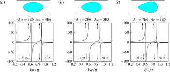
), and also for X-asymmetric variants of these sections. The normalized added-mass coefficients
 $A_{22}$
and
 $A_{66}$
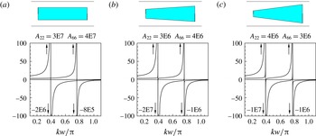
are shown in figures 1 and 2. The singularities, which are obvious features in these plots, indicate the support of trapping modes at the same wavenumbers.
Figure 1(a) shows results for the elliptical cylinder with the major semi-axis
 $a=0.75w$
parallel to the channel walls, and minor semi-axis
 $b=a/2$
. For this case Linton & Evans (Reference Linton and Evans1992a
) find an X-symmetric trapping mode at
 $kw/2=0.960$
and an antisymmetric mode at
 $kw/2=1.398$
. These wavenumbers agree precisely with the singular points in figure 1(a) at
 $kw/\unicode[STIX]{x03C0}=0.6112$
and
 $kw/\unicode[STIX]{x03C0}=0.8901$
. Figure 1(b,c) show asymmetric variants defined by the parametric equations
 $$\begin{eqnarray}\displaystyle x=a\cos \unicode[STIX]{x1D703},\quad y=b\sin \unicode[STIX]{x1D703}+c\sin 2\unicode[STIX]{x1D703},\quad (-\unicode[STIX]{x03C0}\leqslant \unicode[STIX]{x1D703}\leqslant \unicode[STIX]{x03C0}), & & \displaystyle\end{eqnarray}$$
with
 $c/b=1/8,1/4$
.
Sway (
 $A_{22}$
) and yaw (
 $A_{66}$
) added-mass coefficients of the elliptical cylinder (a) and asymmetric variants (b,c) defined by (3.1). The channel width is
 $w$
and
 $k$
is the wavenumber. The sketch at the top in each figure shows a section of the cylinder and channel walls. The maximum and minimum computed values are shown in floating-point format adjacent to each arrow, e.g.
 $3\text{E}6=3\times 10^{6}$
is the maximum positive value of
 $A_{22}$
in (a).

Sway (
 $A_{22}$
) and yaw (
 $A_{66}$
) added-mass coefficients of the rectangular cylinder (a) and asymmetric variants (b,c). See the caption of figure 1 for further information.

Similar results are shown in figure 2 for the rectangular cylinder and two asymmetric trapezoids, all with length
 $L=2w$
and mean width
 $w/2$
. In (b) and (c) the widths of the ends are modified by
 $\pm 0.2w/\unicode[STIX]{x03C0}$
and
 $\pm 0.4w/\unicode[STIX]{x03C0}$
to show the effects of asymmetry. The singularities in (a) at
 $kw/\unicode[STIX]{x03C0}=0.3927$
and
 $kw/\unicode[STIX]{x03C0}=0.7599$
are consistent with the trapped-mode wavenumbers of Evans & Linton (Reference Evans and Linton1991, figure 5), but the accuracy of this comparison is restricted by the graphical form of their results.
It is evident in figures 1 and 2 that asymmetry does not affect the peak magnitudes significantly. This is consistent with the support of trapping shown for a different type of X-asymmetric cylinder by Linton & Evans (Reference Linton and Evans1992a ), and the more general existence proof of Evans et al. (Reference Evans, Linton and Vassiliev1994).
The sway and yaw modes are uncoupled for the X-symmetric structures in figures 1(a) and 2(a). Thus
 $A_{66}$
is continuous and varies slowly at the singularity of
 $A_{22}$
, where the corresponding trapping mode is X-symmetric, and
 $A_{22}$
is continuous at the wavenumber of the antisymmetric mode where
 $A_{66}$
is singular. For the asymmetric structures coupling is evident from the small discontinuities of
 $A_{66}$
at the first trapping mode and
 $A_{22}$
at the second. These effects are larger for the structures in figures 1(c) and 2(c).
The damping coefficients in sway and yaw should vanish if
 $kw/\unicode[STIX]{x03C0}<1$
, since there is no wave radiation below the cut-off. In most cases the computed values are smaller than the corresponding added-mass coefficients by factors of order
 $10^{-6}$
or less. There are exceptions very close to the trapped-mode wavenumbers where this factor is larger, and in some cases the computed damping coefficients are negative.
In previous work by Evans & Linton (Reference Evans and Linton1991), Linton & Evans (Reference Linton and Evans1992a ), and Evans & Porter (Reference Evans and Porter1997), the velocity potential of trapping modes is assumed to be of the form
 $$\begin{eqnarray}\displaystyle \unicode[STIX]{x1D6F7}(x,y,z)=\unicode[STIX]{x1D719}(x,y)\cosh (k(z+h))/\cosh (kh), & & \displaystyle\end{eqnarray}$$
as in the scattering problem where waves with the same dependence on
 $z$
are incident upon a fixed cylinder. The function
 $\unicode[STIX]{x1D719}(x,y)$
, which is governed by the Helmholtz equation, is essentially the same as the potential in the analogous two-dimensional acoustic problem. In this case the depth
 $h$
does not affect the values of the wavenumber where trapping modes are supported.
A numerical test of the validity of (3.2) follows by comparing the added mass for generalized modes of body motion where the displacement in the
 $y$
-direction is modulated by a function
 $f(z)$
, which is related to the vertical eigenfunctions for separable solutions in cylindrical coordinates (cf. Linton & McIver Reference Linton and McIver2001, § 2.1). For rigid-body sway
 $f(z)=1$
. The generalized modes are defined by the orthogonal functions
 $$\begin{eqnarray}\displaystyle & \displaystyle f_{0}(z)=\cosh (k_{0}(z+h))/\cosh (k_{0}h), & \displaystyle\end{eqnarray}$$
 $$\begin{eqnarray}\displaystyle & \displaystyle f_{n}(z)=\cos (k_{n}(z+h))\quad (n=1,2,3,\ldots ). & \displaystyle\end{eqnarray}$$
 $k_{0}$
is the real wavenumber of the trapping mode, defined by the singularity of the sway added mass, and
 $k_{n}$
are the imaginary roots of the dispersion relation at the same frequency. Calculations of the added mass confirm that the results are similar for the sway mode and the mode
 $f_{0}$
, with the same singularity proportional to
 $(k-k_{0})^{-1}$
. The corresponding results for
 $n\geqslant 1$
vary slowly throughout the domain
 $kw/\unicode[STIX]{x03C0}<1$
, with values less than one. Since the functions (
 $f_{0}$
,
 $f_{n}$
) are orthogonal the trapping mode must have the same depth-dependence as
 $f_{0}$
and there is no evidence of any other trapping modes with different depth-dependence, at least for this cylinder.
Appendix B contains a general proof for the validity of (3.2).
4 Y-asymmetric cylinders
Trapping modes can be supported in channels by bodies that are not symmetric about the centreline. Evans et al. (Reference Evans, Linton and Ursell1993) proved that trapping is supported by fixed bottom-mounted vertical plates of zero thickness placed parallel to the walls but off the centreline of the channel. Their results have been confirmed using the present numerical method; the sway and yaw added-mass coefficients are similar to those shown in figures 1 and 2 and the singularities are at the same wavenumbers as in Evans et al. (Reference Evans, Linton and Ursell1993, figure 1). However, the magnitudes of the singular peaks are reduced substantially if a small amount of thickness is added with elliptical or rectangular sections; this suggests that more complicated shapes are required for bodies with finite thickness.

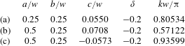
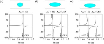
Linton et al. (Reference Linton, McIver, McIver, Ratcliffe and Zhang2002) have shown that trapping is supported by Y-asymmetric bottom-mounted cylinders which are defined by three geometric parameters, including the structure shown in their figure 7 and here in figure 3(a). This cylinder is defined by the equations
 $$\begin{eqnarray}\displaystyle x=a(1-2\unicode[STIX]{x1D6FF})\cos \unicode[STIX]{x1D703},\quad y=b(\sin \unicode[STIX]{x1D703}+\unicode[STIX]{x1D6FF}|\sin \unicode[STIX]{x1D703}|)+c,\quad (-\unicode[STIX]{x03C0}\leqslant \unicode[STIX]{x1D703}\leqslant \unicode[STIX]{x03C0}), & & \displaystyle\end{eqnarray}$$
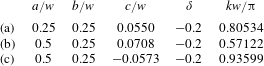
with the values of the geometric parameters shown in line 1 of table 1. Note that (4.1) is generalized from the corresponding equation (3.1) in Linton et al. (Reference Linton, McIver, McIver, Ratcliffe and Zhang2002), with an extra parameter to represent the elongated structures in figure 3(b,c).
The added mass shown in figure 3(a) is singular at
 $kw/\unicode[STIX]{x03C0}=0.8053$
, which agrees precisely with the wavenumber
 $kw/2=1.265$
given by Linton et al. (Reference Linton, McIver, McIver, Ratcliffe and Zhang2002). For this structure the yaw added-mass
 $A_{66}$
is non-singular, with normalized values between 0.4 and 0.9. Thus there is only one trapping mode, which is X-symmetric.
Figure 3(b,c) shows elongated versions of the same shape, with the offset parameter c adjusted to maximize the discontinuity of the added mass. The singularity of
 $A_{22}$
is maximized in 3(b) to find the configuration which supports an X-symmetric trapping mode. In 3(c) the singularity of
 $A_{66}$
is maximized to find the configuration which supports an X-antisymmetric mode. In both cases the other coefficient appears to be singular, but the magnitudes of the peaks are not sufficiently large to indicate trapping. The geometric parameters and the wavenumbers of the trapped modes are shown in table 1.
Unlike the Y-symmetric cylinders in § 3 the damping of these asymmetric cylinders is non-zero, due to the symmetric component of the fluid motion which radiates waves in the far field. For
 $kw/\unicode[STIX]{x03C0}<1$
the damping coefficients
 $B_{22}$
and
 $B_{66}$
are very small, except in the immediate vicinity of the wavenumbers where the added-mass coefficients are singular. At the singular wavenumbers the damping coefficients achieve large positive values, with magnitudes similar to the corresponding added-mass coefficients. In this respect the damping coefficients are similar to those observed for open water in Newman (Reference Newman1999), with singularities that are numerical approximations of
 $\unicode[STIX]{x1D6FF}$
-functions.
5 Other types of fixed bodies
In this section we consider bodies that have three-dimensional shapes and do not extend over the entire fluid depth.
Linton & Evans (Reference Linton and Evans1992b
) have analysed truncated circular cylinders, including case (A) in which the cylinder intersects the free surface with draft
 $D<h$
, and case (B) in which the cylinder is mounted on the bottom with its upper end at the depth
 $z=-D$
. Trapping is found in both cases for a range of fluid depths
 $h$
and body depths
 $D$
. The normalized wavenumbers
 $kw/2$
are listed with an accuracy of two decimal places (Linton & Evans Reference Linton and Evans1992b
, tables 1 and 2) for cylinders with radius
 $a=w/4$
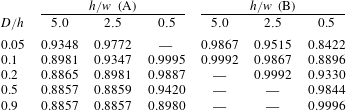
. The same cases are considered here for comparison, with the results shown in table 2. Here the notation is different, but the order of the table is the same as in Linton & Evans (Reference Linton and Evans1992b
, tables 1 and 2). The entries in each row and column can be compared directly, except for a factor of
 $\unicode[STIX]{x03C0}/2$
difference in the normalizations. The only significant differences are where the wavenumber
 $kw/2=1.57$
is given by Linton & Evans (Reference Linton and Evans1992b
) and blank entries are shown in table 2.
Normalized wavenumbers
 $kw/\unicode[STIX]{x03C0}$
for trapping by truncated circular cylinders with radius
 $a=w/4$
. The cylinders (A) are on the free surface, with draft
 $D<h$
. The corresponding wavenumbers are shown in columns 2–4. The cylinders (B) are mounted on the bottom, with the upper end at
 $z=-D$
. The corresponding wavenumbers are shown in columns 5–9. Blank entries indicate that there is no evidence of a trapping mode.
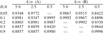
With respect to case (A), the first blank entry in table 2 represents a cylinder on the free surface with
 $h/w=0.5$
and
 $D/h=0.05$
; the present calculations indicate that no trapped mode exists for this cylinder below the cut-off at
 $kw/\unicode[STIX]{x03C0}=1$
. This conclusion is based on calculations at a large number of closely-spaced wavenumbers just below the cut-off, which show small continuous values of the added mass. Additional computations for the same fluid depth indicate that the minimum draft for trapping is between
 $D/h=0.075$
and
 $0.080$
. This differs from the conclusion of Linton & Evans (Reference Linton and Evans1992b
) that a trapped mode exists for the cylinder
 $D/h=0.05$
in the range
 $1.565<kw/2<\unicode[STIX]{x03C0}/2$
.
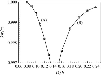
Further evidence is provided by the curve (A) in figure 4, which shows the wavenumbers for trapping by cylinders with
 $0.08\leqslant D/h\leqslant 0.13$
in the same fluid depth. The continuation of this curve appears to intersect the cut-off
 $kw/\unicode[STIX]{x03C0}=1$
just below
 $D/h=0.080$
, confirming that there is no trapped mode below the cut-off for smaller values of the draft. The extrapolation of this curve above the cut-off suggests the possibility of a trapped mode which is embedded in the continuous spectrum, as has been discovered for a bottom-mounted cylinder by Evans & Porter (Reference Evans and Porter1998). However computations with smaller drafts just above the cut-off, in the vicinity of the extension of curve (A), show no indications of singular behaviour.
It is not possible to draw similar conclusions for cylinders (B), where blank entries are shown for the larger values of
 $D/h$
in columns 5 and 6 of table 2. The curve (B) in figure 4 does not show any indication of intersecting the cut-off as the depth is increased. Calculations to extend this curve for larger values of
 $D/h$
are not considered reliable due to increasing scatter near the cut-off.
Wavenumbers of trapped modes for the truncated circular cylinders. The curve (A) is for cylinders on the free surface with the draft
 $D$
and fluid depth
 $h=w/2$
, corresponding to the data in column 4 of table 2. The curve (B) is for cylinders mounted on the bottom with the upper end at depth
 $D$
and the fluid depth
 $h=2.5w$
, corresponding to the data in column 6.

Next we consider a variety of elongated bodies which intersect the free surface with draft
 $D<h$
, including truncated cylinders with the same elliptical and rectangular sections described in § 3 and ellipsoids with semi-axes
 $a,b,c$
. For the ellipsoids the length
 $L=2a$
and beam
 $B=2b$
are fixed with the values
 $L=2w$
,
 $B=3w/4$
and the draft
 $D=c$
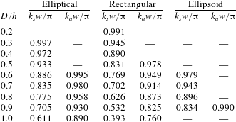
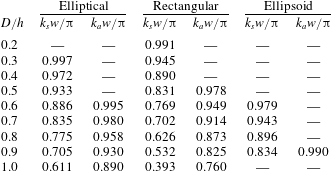
is varied. For all of these bodies the sway and yaw added mass are similar to the corresponding coefficients shown in figures 1–3, but the existence of singularities depends on the draft. The results are summarized in table 3. As the ratio
 $D/h$
decreases the trapped-mode wavenumbers increase and approach the cut-off
 $kw/\unicode[STIX]{x03C0}=1$
in the same manner as for the truncated circular cylinders (A) in table 2. The blank entries in table 3 indicate values of
 $D/h$
where there is no evidence of a singularity in the corresponding added-mass coefficient for
 $kw/\unicode[STIX]{x03C0}<1$
. Thus the minimum value of
 $D/h$
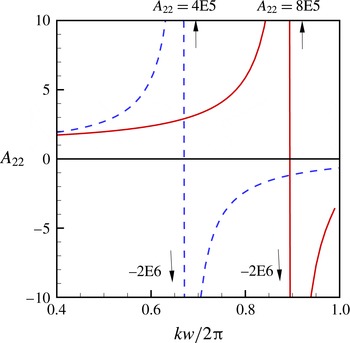
in each case is between the values shown for the last blank line and the first non-blank line. The solid line in figure 5 shows the sway added-mass coefficient of the ellipsoid
 $D/h=0.8$
. For this draft the yaw added mass is non-singular.
Added-mass coefficients
 $A_{22}$
for the ellipsoid with semi-axes
 $a=w$
,
 $b=3w/8$
. For the floating case (solid lines) the draft is
 $D=c=0.8h$
. For the submerged case described in § 8 (dashed lines),
 $c=0.4h$
and the centre of the ellipsoid is at
 $z=-h/2$
.

Wavenumbers for X-symmetric (
 $k_{s}$
) and antisymmetric (
 $k_{a}$
) trapping by fixed bodies for different values of the draft/depth ratio (
 $D/h$
). The results on the last line (
 $D/h=1$
) are for the bottom-mounted cylinders in § 3.
6 X-symmetric motion trapping
Vertical heave motion is considered for bodies which are symmetric about
 $x=0$
and
 $y=0$
. Thus there is no coupling with the other modes of rigid-body motion, and it follows from (2.2) that the conditions for motion trapping are
 $$\begin{eqnarray}\displaystyle & \displaystyle \text{Re}(F_{33})=-\unicode[STIX]{x1D714}^{2}(A_{33}+m)+C_{33}=0, & \displaystyle\end{eqnarray}$$
 $$\begin{eqnarray}\displaystyle & \displaystyle \text{Im}(F_{33})=\unicode[STIX]{x1D714}B_{33}=0. & \displaystyle\end{eqnarray}$$
The force coefficients in (6.1) and (6.2) can be computed in a straightforward manner. However the damping is positive-definite, as a function of
 $k$
, and if a zero exists it must be quadratic. In the numerical scheme where small errors exist it is not possible to establish the existence of a quadratic zero with certainty. To avoid this problem the heave exciting force
 $X_{3}$
is used as a surrogate parameter. In the domain
 $kw<2\unicode[STIX]{x03C0}$
, where the radiated waves in the far-field are two-dimensional, it follows from the Haskind relations that
 $B_{33}=C|X_{3}|^{2}$
where
 $C$
is a positive real factor (cf. Linton & McIver Reference Linton and McIver2001, pp. 17–18). Thus, if there is a wavenumber where
 $B_{33}=0$
, the same wavenumber is a simple zero of
 $X_{3}$
which can be identified with more certainty in the numerical scheme. Since
 $X_{3}$
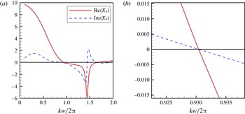
is complex it is necessary to ensure that both the real and imaginary parts vanish at the same point. This is evident from the plots of the results, and confirmed by the numerical data which show that the argument of
 $X_{3}$
is never close to
 $\pm \unicode[STIX]{x03C0}/2$
for
 $kw/2\unicode[STIX]{x03C0}<1$
. Thus if
 $\text{Re}(X_{3})$
passes through zero it follows that
 $\text{Im}(X_{3})=0$
and
 $B_{33}=0$
at the same point.
The first example is a prolate spheroid with major semi-axis
 $a=w/2$
, directed along the
 $x$
-axis, and equatorial radius
 $b$
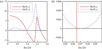
. Figure 6 shows the real and imaginary parts of
 $F_{33}$
for
 $b/a=1/4$
. The magnified plot shows that the simple zero of
 $\text{Re}(F_{33})$
is at a slightly smaller value of
 $k$
relative to the quadratic zero of
 $\text{Im}(F_{33})$
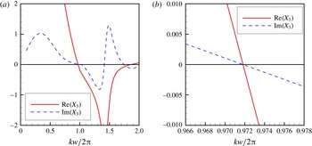
. Figure 7 shows the exciting force
 $X_{3}$
, confirming that the quadratic zero is exact. Similar computations have been performed for other values of
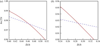
 $b/a$
, with the values of the zero-crossings plotted in figure 8(a) as functions of the draft/depth ratio
 $D/h$
. The curves for the real and imaginary parts intersect at
 $D/h=0.463$
(
 $b/a=0.231$
) and
 $kw/2\unicode[STIX]{x03C0}=0.976$
, indicating that motion trapping exists at this point.
Real part (solid lines) and imaginary part (dashed lines) of the vertical force coefficient
 $F_{33}$
for the spheroid with
 $b/a=1/4$
. The plot on the right is magnified to show the local values near the zeros.

Real part (solid lines) and imaginary part (dashed lines) of the heave exciting force
 $X_{3}$
for the spheroid with
 $b/a=1/4$
. The plot on the right is magnified to show that the zero-crossings are at the same point.

Values of the wavenumber where
 $\text{Re}(F_{33})=0$
(solid lines) and
 $\text{Im}(F_{33})=0$
(dashed lines) for the spheroid (a) and the barge (b), as functions of the draft/depth ratio
 $D/h$
.

The second example is a barge of length
 $L$
, beam
 $B$
and draft
 $D$
, similar to the truncated rectangular cylinders in § 5. Computations are performed for
 $L=w$
and
 $B/L=1/4$
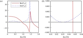
, with variations of the draft. Figure 9 shows
 $\text{Re}(F_{33})$
and
 $\text{Im}(F_{33})$
for
 $D/h=1/4$
. The zeros of the real and imaginary parts of the exciting force
 $X_{3}$
shown in figure 10 coincide in the same manner as in figure 7, confirming that the quadratic zero for the damping coefficient is exact. Similar computations have been performed for other values of
 $D/h$
, with the values of the zero-crossings shown in figure 8(b). The intersection at
 $D/h=0.287$
and
 $kw/2\unicode[STIX]{x03C0}=0.926$
indicates that motion trapping exists at this point.
Real part (solid lines) and imaginary part (dashed lines) of the vertical force coefficient
 $F_{33}$
for heave of the barge with
 $D/h=1/4$
. The plot on the right is magnified to show the local values near the zero-crossings.

Real part (solid lines) and imaginary part (dashed lines) of the heave exciting force
 $X_{3}$
for the barge with
 $D/h=1/4$
. The plot on the right is magnified to show that the zero-crossings are at the same point.

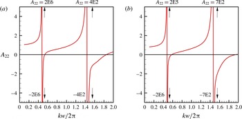
Added-mass coefficients
 $A_{22}$
of the motion-trapping spheroid (a) and barge (b). The singularities at
 $kw/2\unicode[STIX]{x03C0}=0.482$
in (a) and
 $kw/2\unicode[STIX]{x03C0}=0.481$
in (b) indicate trapping modes at these wavenumbers if the bodies are fixed.

The sharp peaks and rapid variation in these figures near
 $kw/2\unicode[STIX]{x03C0}=1.5$
are attributed to resonant cross-waves in the gaps between the body and the walls. This resonance is larger for the barge due to the constant width of the gaps. The zero or near-zero values of
 $F_{33}$
near
 $kw/2\unicode[STIX]{x03C0}=1.7$
are discussed in § 9.
Figure 11 shows the sway added-mass coefficients of the spheroid
 $b/a=0.231$
and barge
 $D/h=0.287$
, which support motion trapping. In figure 11(a) the singularity at
 $kw/2\unicode[STIX]{x03C0}=0.482$
indicates an X-symmetric trapping mode for the spheroid if it is fixed. Similarly in figure 11(b) the singularity at
 $kw/2\unicode[STIX]{x03C0}=0.481$
indicates an X-symmetric trapping mode for the fixed barge. Thus these particular bodies can support two different trapping modes, one if they are fixed and the other if they are free to heave.
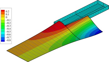
In addition to the existence of motion trapping at specific values of the beam and draft, the heave damping is zero for a range of values as indicated by the dashed curves in figure 8; thus these bodies can oscillate in the heave mode without radiating waves in the far field. Figure 12 shows a contour plot of the free-surface elevation for the barge
 $D/h=1/4$
at
 $kw/2\unicode[STIX]{x03C0}=0.930$
, where there are no radiated waves. Heaving bodies with small water-plane areas (compared with the area of horizontal sections below the free surface) are ‘wave-free’ at one wavenumber, due to cancellation of the waves generated by the normal velocities above and below the point of maximum area (cf. Kyozuka & Yoshida Reference Kyozuka and Yoshida1981). However the spheroid and barge do not have this shape, and it is surprising that bodies such as these can be wave-free in a channel. Figure 12 suggests that there is cancellation in this case between the positive upward heaving motion of the body and the negative free-surface elevation near the wall abeam of the vessel.
Contour plot of the free-surface elevation for unit heave amplitude of the barge
 $D/h=1/4$
at the wavenumber
 $kw/2\unicode[STIX]{x03C0}=0.930$
, where the damping is zero. At this wavenumber the elevation is real, oscillating in proportion to
 $\cos \unicode[STIX]{x1D714}t$
. The plot shows the elevation at time
 $t=0$
, when the heaving motion is positive upwards. Only one quadrant of the free surface is shown since the elevation is symmetric about
 $x=0$
and
 $y=0$
.

7 X-antisymmetric motion trapping
If the body is free to surge in the longitudinal direction (
 $i=1$
) and pitch about the transverse axis (
 $i=5$
) the motion is X-antisymmetric. The equations of motion are coupled, with the elements of the coefficient matrix
 $$\begin{eqnarray}\displaystyle & \displaystyle F_{11}=-\unicode[STIX]{x1D714}^{2}(A_{11}+m)+\text{i}\unicode[STIX]{x1D714}B_{11}, & \displaystyle\end{eqnarray}$$
 $$\begin{eqnarray}\displaystyle & \displaystyle F_{15}=-\unicode[STIX]{x1D714}^{2}(A_{15}+mz_{g})+\text{i}\unicode[STIX]{x1D714}B_{15}, & \displaystyle\end{eqnarray}$$
 $$\begin{eqnarray}\displaystyle & \displaystyle F_{51}=F_{15}, & \displaystyle\end{eqnarray}$$
 $$\begin{eqnarray}\displaystyle & \displaystyle F_{55}=-\unicode[STIX]{x1D714}^{2}(A_{55}+mk_{yy}^{2})+\text{i}\unicode[STIX]{x1D714}B_{55}+C_{55}. & \displaystyle\end{eqnarray}$$
 $m$
is the body mass, distributed symmetrically about
 $x=0$
,
 $z_{g}$
is the vertical coordinate of the centre-of-gravity, and
 $k_{yy}$
is the radius of gyration about the
 $y$
-axis.
 $C_{55}$
includes the hydrostatic restoring moment and the gravitational moment
 $-mgz_{g}$
.
Motion trapping is supported if the determinant
 $|F_{ij}|=0$
. This is achieved in the examples below by finding suitable combinations of the parameters such that
 $F_{15}=0$
and
 $F_{55}=0$
.
 $z_{g}$
and
 $k_{yy}$
can be varied independently of the wavenumber and body geometry, as long as they are within physically reasonable limits, to satisfy the conditions
 $\text{Re}(F_{15})=0$
and
 $\text{Re}(F_{55})=0$
. A more fundamental question is if it is possible to find a suitable combination of the geometry and wavenumber such that the damping coefficients
 $B_{15}$
and
 $B_{55}$
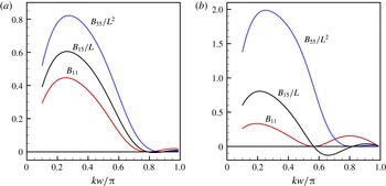
are both zero. This may seem unlikely, but if the body is wave-free in the pitch mode in an analogous manner to that shown for heave in figure 12, the corresponding pressure is real, and thus both
 $B_{15}$
and
 $B_{55}$
are equal to zero at the same wavenumber. Similarly, if there is a different wavenumber where the body is wave-free in surge and the corresponding pressure is real, both
 $B_{11}$
and
 $B_{51}$
are zero. Since
 $B_{15}=B_{51}$
from reciprocity, these coefficients have zeros at both wavenumbers as shown in figure 13.
Damping coefficients of the spheroid (a) and barge (b) in the surge (
 $i=1$
) and pitch (
 $i=5$
) modes, for the cases where
 $L/w=1.8$
. The cross-coupling coefficients
 $B_{15}$
have simple zeros at the wavenumbers where
 $B_{11}=0$
and
 $B_{55}=0$
.

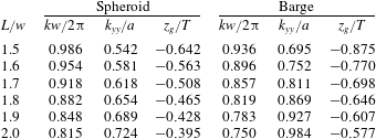
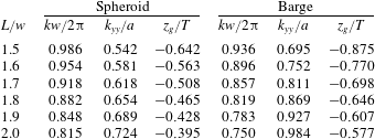
Table 4 shows examples of motion trapping for the spheroid and barge. The minor semi-axis of the spheroid is
 $b=w/8$
, corresponding to a beam
 $B=w/4$
and draft
 $D=w/8$
. For the barge
 $B=w/4$
and
 $D=w/16$
. Combinations of the length and wavenumber that support motion trapping are shown for
 $L/w$
between 1.5 and 2.0. This data is assembled in the following manner. For each value of
 $L/w$
the wavenumber is found where the pitch exciting moment
 $X_{5}=0$
, and thus
 $B_{55}=0$
and
 $B_{15}=0$
. Then
 $z_{g}$
is evaluated to make the real part of (7.2) equal to zero. Finally, the radius of gyration
 $k_{yy}$
is found to make the real part of (7.4) equal to zero. If the distribution of the body mass is restricted to the internal volume, the physical limits for these parameters are
 $k_{yy}<L/2=a$
and
 $z_{g}>-T$
. The wavenumber is assumed to be below the cut-off
 $kw/2\unicode[STIX]{x03C0}=1$
. These restrictions limit the range of
 $L/w$
.
Comparing the X-symmetric trapping modes associated with heave and the antisymmetric modes associated with surge and pitch, the body must be longer to support antisymmetric modes, as in the case of fixed bodies in § 5. On the other hand, the parameters
 $k_{yy}$
and
 $z_{g}$
can be adjusted to satisfy the requirements that (7.2) and (7.4) vanish. Thus there is more freedom to assign the dimensions of the body to support antisymmetric modes.
Conditions for X-antisymmetric trapping with the body free in the surge and pitch modes.
 $L/w$
is the ratio of the body length to the channel width,
 $kw/2\unicode[STIX]{x03C0}$
is the normalized wavenumber,
 $k_{yy}/a$
is the ratio of the radius of gyration to the half-length
 $a=L/2$
, and
 $z_{g}/T$
is the ratio of the vertical coordinate of the centre of gravity to the draft.
8 Trapping by submerged ellipsoids
Submerged ellipsoids with semi-axes
 $a$
–
 $c$
are considered to illustrate the support of trapping if the body is below the free surface. The length
 $L=2a=2w$
and beam
 $B=2b=3w/4$
are fixed, with the same dimensions as the floating ellipsoid in § 5. The body centre is at
 $z=-h/2$
and the body depth
 $D=2c$
is varied.
The sway added-mass coefficient is shown in figure 5 for
 $D/h=0.8$
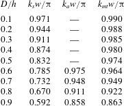
, and compared with the same coefficient for the floating ellipsoid. It is evident that an X-symmetric trapping mode is supported in both cases if the body is fixed. The trapped-mode wavenumbers are summarized in table 5 for the submerged body. X-symmetric trapping modes are supported for all values of
 $D/h$
, and antisymmetric modes for
 $D/h\geqslant 0.6$
. It is interesting to note that trapping modes are supported by the submerged ellipsoid for all values of
 $D/h$
whereas the results for the floating body in table 3 show that the draft must be greater than half the depth.
Another difference between the floating and submerged ellipsoids is the Y-symmetry of motion trapping. No examples have been found for submerged bodies where the heave (or pitch) damping is zero, but Y-antisymmetric modes of body motion are wave-free below the cut-off
 $kw=\unicode[STIX]{x03C0}$
, and the corresponding damping coefficients are zero. Thus for a body that is free in the sway mode, where there is no hydrostatic or gravitational restoring force, motion trapping is supported if
 $$\begin{eqnarray}\displaystyle A_{22}+m=0. & & \displaystyle\end{eqnarray}$$
The results in figure 5 indicate that this condition is satisfied only in the submerged case, at the wavenumber
 $kw/\unicode[STIX]{x03C0}\simeq 0.92$
where
 $A_{22}/m=-1$
. For the floating bodies considered in § 6 either
 $A_{22}>0$
or
 $A_{22}<-m$
in the domain
 $kw<\unicode[STIX]{x03C0}$
.
Wavenumbers for X-symmetric (
 $k_{s}$
) and antisymmetric (
 $k_{a}$
) trapping modes supported by fixed submerged ellipsoids with different values of the ratio (
 $D/h$
).
 $D=2c$
is the body-depth. The centre is at
 $z=-h/2$
. The last column shows the wavenumbers
 $k_{mt}$
for motion-trapping modes supported by the same body if it is free in the sway mode.
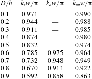
The last column of table 5 shows the wavenumbers where (8.1) is satisfied. Comparison of the data in the last two columns of this table shows that they are equal if
 $D/h$
is slightly less than 0.7. Further computations reveal that (8.1) is satisfied for the ellipsoid with
 $D/h=0.692$
at
 $kw/\unicode[STIX]{x03C0}=0.951$
and the yaw added-mass coefficient
 $A_{66}$
is singular at the same wavenumber. Thus for this specific geometry the X-antisymmetric trapping mode for the fixed body and the symmetric motion-trapping mode for the free body occur at the same frequency.
Similar computations indicate that X-antisymmetric trapping is supported if the body is free to yaw about the
 $z$
-axis and the moment of inertia
 $I_{66}$
is adjusted to cancel the negative added-mass coefficient
 $A_{66}$
. This is possible only for the two deepest ellipsoids in table 5, if the distribution of the body mass is restricted to the internal volume, since these are the only cases where
 $-ma^{2}<A_{66}<0$
.
The effect of coupling between sway and roll has not been considered. These modes can be uncoupled by adjusting the moment of inertia
 $I_{44}$
and the vertical position of the centre of gravity.
9 Conclusions
The support of trapping modes in a channel has been demonstrated for several bodies, including the two types of trapping where the body is fixed or free to move in response to the oscillatory pressure. For the spheroid and barge described in § 6, and also for the submerged ellipsoids in § 8, both types of trapping are supported by the same body at different wavenumbers. In one particular case for the submerged ellipsoid, X-antisymmetric trapping of the fixed body and X-symmetric motion trapping of the free body occur at the same frequency.
The simple shapes of these bodies, and the straightforward manner in which they are derived, suggest that bodies that support trapping modes in channels are ubiquitous. Trapping by fixed Y-symmetric structures is easily demonstrated over a range of geometric parameters. For Y-asymmetric structures the geometry is more restricted. Motion trapping is also found for simple shapes, but the geometric parameters are restricted by the requirement that both the real and imaginary parts of the complex force coefficients vanish at the same wavenumber.
Tables 1–5 list the relevant geometric parameters and wavenumbers where trapping is supported for various cases. Comparisons with previous works are favourable in most cases. The only discrepancy is noted in § 5, for a truncated circular cylinder with shallow draft. For that particular case a trapped mode very close to the cut-off is reported by Linton & Evans (Reference Linton and Evans1992b ), whereas the present computations show no evidence of this mode. Other examples are also shown in table 3 of elongated bodies where there is no trapping if the draft is less than a minimum value. The discrepancy for the truncated circular cylinder would benefit from further investigation.
Since the results are numerical, it is important to consider their validity in establishing the existence of ‘pure’ trapping modes. Trapping by a fixed body at the wavenumber
 $k=k_{0}$
is indicated by a singularity of the added-mass coefficient proportional to
 $(k-k_{0})^{-1}$
. In the figures showing
 $A_{22}$
and
 $A_{66}$
versus
 $k$
the singularities are clearly of this form, at least within the accuracy of the plots. The maximum absolute values of the normalized added-mass coefficients are of order
 $10^{5}{-}10^{6}$
. Since the computations are performed in single precision these magnitudes are sufficiently large to assume that they correspond to analytic singularities and represent pure trapping modes. In addition to their large magnitudes the adjacent peaks are nearly contiguous, giving close numerical approximations to the expected singularities; for example the values shown for the positive and negative peaks of
 $A_{22}$
in figure 1(a) are computed at
 $kw/\unicode[STIX]{x03C0}=0.611185$
and
 $kw/\unicode[STIX]{x03C0}=0.611186$
. For the bottom-mounted cylinders in §§ 3 and 4 the agreement of the singular wavenumbers with the results in Evans & Linton (Reference Evans and Linton1991), Linton & Evans (Reference Linton and Evans1992a
) and Linton et al. (Reference Linton, McIver, McIver, Ratcliffe and Zhang2002) supports the conclusion that these are pure trapping modes. This provides substantial confidence that the same conclusion applies for the other bodies where the same numerical method is used.
The demonstration of ‘pure’ motion trapping by free bodies is more conclusive, without regard for the effects of small numerical errors. This is explained in § 6, where the existence of quadratic zeros of the damping coefficients are based on corresponding first-order zeros of the exciting forces, and the coincidence of the zeros for the real and imaginary parts of the force are based on the intersections of two lines in the geometric parameter space.
Y-symmetric geometry of the bodies has been assumed in most cases. The exceptions are bottom-mounted cylinders with special shapes described in § 4, which are motivated by the Y-asymmetric structure found by Linton et al. (Reference Linton, McIver, McIver, Ratcliffe and Zhang2002). X-symmetry is not required for trapping by fixed vertical cylinders, as shown by Linton & Evans (Reference Linton and Evans1992a ) and Evans et al. (Reference Evans, Linton and Vassiliev1994), and by the results for the asymmetric structures in figures 1 and 2. No examples are known where the body is asymmetric about both planes, but it is not likely that this is a fundamental obstacle to the support of trapping by fixed bodies. Similar results are expected for floating or submerged bodies which do not extend from the free surface to the bottom.
In the investigations of motion trapping both transverse and longitudinal body symmetry have been assumed. Both symmetric and antisymmetric trapping modes are demonstrated. For floating bodies the X-symmetric modes are associated with a single degree of freedom in heave. X-antisymmetric modes are associated with coupled motions in surge and pitch. Antisymmetric modes require a longer body but there is more freedom to assign the beam and draft since the radius of gyration and vertical coordinate of the centre of gravity are free parameters. It is important, and somewhat surprising, that both the pitch damping coefficient
 $B_{55}$
and the cross-coupling coefficient
 $B_{15}$
are equal to zero at the same wavenumber. This is explained by the fact that the pressure field is real throughout the fluid domain at the wavenumber where no radiated waves are generated by pitching motion of the body. In all of these cases the body motions and trapping modes are Y-symmetric.
Y-antisymmetric trapping modes of submerged ellipsoids are established in § 8, both for fixed bodies and for bodies that are free in sway or yaw. No cases have been found where Y-antisymmetric motion-trapping modes are supported by floating bodies, or Y-symmetric modes by submerged bodies.
The investigations of trapping by fixed bodies in §§ 3–5 are restricted to wavenumbers below the cut-off
 $k=\unicode[STIX]{x03C0}/w$
for Y-antisymmetric waves, and similarly for motion trapping by submerged ellipsoids in § 8. This restriction is especially helpful to establish Y-antisymmetric motion trapping, since there is no wave damping. For Y-symmetric motion trapping by floating bodies in §§ 6 and 7 the wavenumbers are below the cut-off
 $k=2\unicode[STIX]{x03C0}/w$
; thus the radiated waves are two-dimensional and the Haskind relations can be used to ensure that the quadratic zeros of the damping coefficients are exact.
Evans & Porter (Reference Evans and Porter1998) have shown that trapping is supported above the cut-off by a bottom-mounted circular cylinder, but only for one unique combination of the radius and wavenumber relative to the channel width. It is likely that other fixed structures with isolated values of their dimensions support trapping above the cut-off, but it may be difficult to search for these in the multidimensional parameter space.
With respect to motion trapping above the cut-off wavenumber, it is interesting to note in figures 6 and 9 that
 $\text{Re}(F_{33})=0$
and
 $\text{Im}(F_{33})$
is very small, near
 $kw/2\unicode[STIX]{x03C0}=1.7$
. Extensive calculations have been made in this regime searching for bodies where
 $F_{33}=0$
, with negative results. Combinations of the dimensions can be found such that the heave damping is practically zero, but it is not possible to confirm that this quadratic zero is exact and it is always at a wavenumber greater than the zero of
 $\text{Re}(F_{33})$
. These results suggest that, for the simple types of structures considered here, motion-trapping is only supported in the heave mode below the cut-off
 $k=2\unicode[STIX]{x03C0}/w$
. On the other hand, motion trapping is supported in open water by other types of structures, such as the toroids of McIver & McIver (Reference McIver and McIver2007). This implies that special types of bodies may support motion trapping above the cut-off in a channel of sufficiently large width.
The results shown here are based on computations for a limited sample of body shapes and channel dimensions. These restrictions may affect the conclusions, particularly with regard to the requirements for geometrical symmetry. Establishing proofs, or demonstrating counter-examples, are challenging problems for theoretical research.
Acknowledgements
This work was motivated by stimulating discussions at the 31st International Workshop on Water Waves and Floating Bodies (IWWWFB 2016). I am grateful to the referees for their comments and suggestions, including the proof in appendix B.
Appendix A. Computational notes
The present computations have been performed using the radiation-diffraction code WAMIT. This program uses the boundary-integral-equation method to solve for the velocity potential based on Green’s theorem. The Green function (cf. Linton & McIver Reference Linton and McIver2001, appendix B.3) satisfies the boundary conditions on the free surface and bottom, and the radiation condition in the far field. Thus the computational domain for bodies in open water is restricted to the submerged surface of the body. For the analysis of bodies in channels the Green function is extended to satisfy the boundary condition on the walls using the method of images with accelerated convergence, as described by Newman (Reference Newman2016).
The numerical solution is based on analytic representation of the body surface and B-spline representation of the unknown velocity potential. This provides greater accuracy compared to the conventional low-order panel method where the geometry is approximated by quadrilateral elements and the potential is represented on each element by a constant or linear function.
The accuracy of the numerical results is controlled by discretization parameters that determine the number of unknown B-spline coefficients. These parameters have been adjusted in the present calculations with the objective of achieving an accuracy of five decimals for the computed force coefficients, and the same accuracy in the computations of the wavenumbers where trapping is supported. This accuracy has been verified by convergence tests in subsets of the results.
For the analysis of plates with zero thickness described in § 4, to compare with the results of Evans et al. (Reference Evans, Linton and Ursell1993), a modified integral equation is used with a distribution of normal dipoles on the body surface. For further details see WAMIT, Inc. (2016).
Appendix B. Proof of (3.2)
For bottom-mounted cylinders the velocity potential can be expanded in the form
 $$\begin{eqnarray}\displaystyle \unicode[STIX]{x1D719}(x,y,z)=\mathop{\sum }_{n=0}^{\infty }\unicode[STIX]{x1D719}_{n}(x,y)f_{n}(z), & & \displaystyle\end{eqnarray}$$
where the functions
 $f_{n}(z)$
are defined by (3.3) and (3.4). From the governing Laplace equation it follows that
 $$\begin{eqnarray}\displaystyle (\unicode[STIX]{x1D6FB}^{2}-k_{n}^{2})\unicode[STIX]{x1D719}_{n}(x,y)=0\quad \text{for }(n>0). & & \displaystyle\end{eqnarray}$$
Since the boundary conditions on the cylinder and wall are homogeneous and the potential of a trapped mode vanishes at infinity, it follows from Green’s theorem that
 $$\begin{eqnarray}\displaystyle \int _{D}(|\unicode[STIX]{x1D735}\unicode[STIX]{x1D719}_{n}|^{2}+k_{n}^{2}|\unicode[STIX]{x1D719}_{n}|^{2})\,\text{d}S=0\quad \text{for }(n>0), & & \displaystyle\end{eqnarray}$$
where
 $D$
is the two-dimensional plane of the fluid domain. Since
 $k_{n}$
is real,
 $\unicode[STIX]{x1D719}_{n}=0$
is the only solution for
 $n>0$
.
This proof has been suggested by the referees.