I. INTRODUCTION
The rapid increase of communication standards such as Wireless local area network (WLAN), Worldwide interoperability for microwave access (WiMAX), UMTS, and ultra-wideband (UWB) etc. leads to a great demand in developing multiband internal antennas for wireless communication devices [Reference Manafi, Nikmehr and Bemani1]. Recently, the ability to integrate more than one communication standard into a single system has become an increasing demand for modern portable wireless communication devices, such as mobile phones and laptops [Reference Liu, Wu and Chu2]. Naturally, this directly impacts the required characteristics of antennas that need to support dual- or multiband channels transmission. Printed antennas have been paid great attention in recent years because of their compact size, low profile, light weight, and low cost [Reference Wang and He3]. A great quantities of printed antennas for multiband or ultra-wideband operations have been reported in the literature [Reference Manafi, Nikmehr and Bemani1].
Recently, a considerable amount of researches have been devoted to the development of UWB antenna for its enabling high data transmission rates, low-power consumption, and simple hardware configuration in wireless applications such as radio frequency identification devices, sensor networks, radar, location-tracking system, and so forth. The UWB antennas of such systems should have small size and wideband properties [Reference McKinney and Weiner4]. The commercial application of the frequency band from 3.1 to 10.6 GHz was approved by the Federal Communication Commission (FCC) in America in 2002 [5].
For dual- or multiband operation, many promising planar antenna designs with microstrip-line-fed in [Reference Manafi, Nikmehr and Bemani1, Reference Wang and He3, Reference Meloui, Akhchaf, Bassouh, Nabil Srifi and Essaaidi6, Reference Foudazi, Hassani and Nezhad8, Reference Wu, Wei, Shi and Li9, Reference Al-Husseini, Tawk, El-Hajj and Kabalan11] and the coplanar waveguide (CPW)-feed in [Reference Liu, Wu and Chu2, Reference Shinde, Mishra and Shinde7, Reference Chang, Yang, Yang and Li10] have been reported. In [Reference Wang and He3], the microstrip-fed modified broadband T-shaped monopole antenna with three inverted U-shaped slots with different sizes is suitable for Bluetooth, WiMAX, and WLAN applications. A diamond-shaped patch with several strips, suitable for UWB/Global positioning system (GPS)/ Global system for mobile (GSM) applications, is presented in [8]. In [Reference Chang, Yang, Yang and Li10], the CPW fed two umbrella printed wideband antennas are suitable for WLAN/WiMAX/UWB applications.
In this investigation, a compact microstrip-fed rectangular-shaped ring antenna embedded with three inverted “S”-shaped and inverted “C”-shaped strips has been proposed to achieve broader bandwidth covering some parts of WLAN operations in 5.2 and 5.8 GHz frequency bands, WiMAX operations in 3.5 and 5.5 GHz frequency bands and UWB antenna ranges from 3.1 to 10.6 GHz with four band notches. The parametric studies are performed to understand the characteristics of the proposed antenna. The advantage of the proposed antenna is that it is more compact than the antennas reported so far [Reference Manafi, Nikmehr and Bemani1, Reference Liu, Wu and Chu2, Reference Meloui, Akhchaf, Bassouh, Nabil Srifi and Essaaidi6, Reference Wu, Wei, Shi and Li9]. The proposed design occupies a size of 24.75 × 27.39 × 1.6 mm3 as compared to combination of a half-disc patch and a rectangular patch, which occupies a large volume of 44.1 × 43 × 1.5 mm3 [Reference Wu, Wei, Shi and Li9]. The design of antenna structure, simulated results, and measured result has been presented in the following sections. The simulated and measured results show that it can be used for both partially UWB and WLAN/WiMAX applications.
II. ANTENNA DESIGN
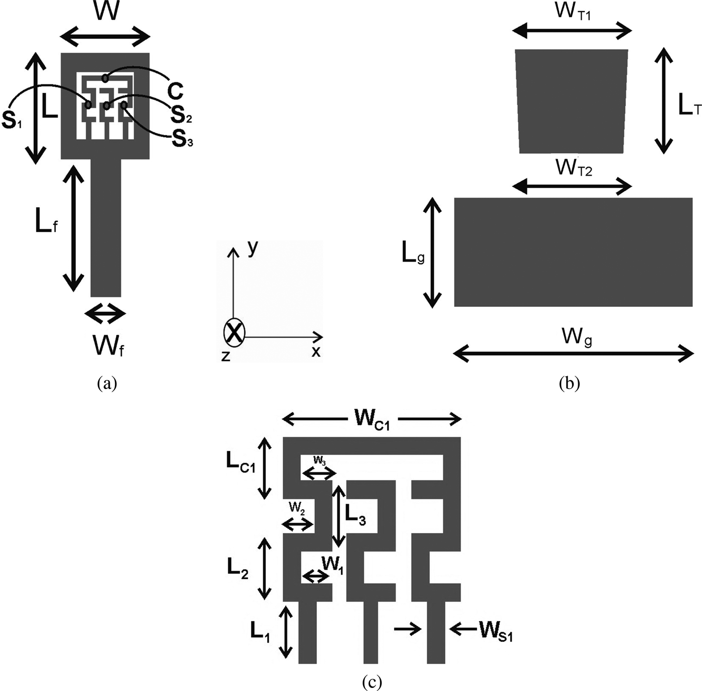
The geometry of the proposed multiband antenna for heterogeneous wireless communication applications is shown in Fig. 1. The rectangular-shaped ring antenna is fed by a microstrip feed and is fabricated on a 1.6-mm-thick FR4 substrate, having relative permittivity of 4.4 with copper cladding on both sides of the substrate. The basic structure of the proposed antenna is a T-shaped monopole with a trapezoidal conductor-backed plane, which is responsible for generating the upper frequency band of the proposed antenna. The basic T-shape is extended to form the rectangular-shaped ring, which is connected at the end by a 50-Ω transmission line of 3-mm wide with a length of 13.97 mm.
Geometry of the microstrip-fed proposed antenna. (a) Front view, (b) back view, and (c) dimensions of inverted “S”- and “C”-shaped strips.

The basic radiating patch is a rectangular-shaped ring, which has dimensions of length L and width W. A simple rectangular-shaped conducting ground plane of width W g and length L g is placed on the other side of the substrate. The rectangular-shaped ring is embedded with three inverted “S”- and “C”-shaped strips, which produces the lower-frequency bands. The widths of all the meandering strips are equal in the proposed antenna. The optimized geometrical parameters describing the proposed antenna are tabulated in Table 1. The overall dimensions of the proposed antenna are 24.75 mm × 27.4 mm × 1.6 mm with volumetric size of approximately 1 cm3. The performance of the antenna has been analyzed by using the method of moment-based Zeland IE3D simulator. The photograph of the fabricated prototype is shown in Fig. 2.
Prototype of fabricated antenna. (a) Front view and (b) back view.
Optimized parameters of the proposed antenna.
III. RESULTS AND DISCUSSION
The simulated return losses are presented for the optimized set of antenna parameters in Fig. 3. From the simulated results, it is apparent that a single antenna having five multiple resonant frequencies with wide bandwidth are obtained. The results has a 10-dB impedance bandwidth for the first band ranging from 3.416 to 4.032 GHz, second band from 4.312 to 5.124 GHz, third band from 5.3 to 6.44 GHz, fourth band from 8.036 to 10.78 GHz, and fifth band from 11.78 to 13.38 GHz. The proposed antenna has a broader bandwidth covering the required bandwidths of the IEEE 802.11 WLAN standards in the bands at some parts of 5.2 GHz (5.150–5.350 GHz) and 5.8 GHz (5.725–5.825 GHz); WiMAX standard in the bands at 3.5 GHz (3.4–3.690 GHz), and 5.5 GHz (5.250–5.850 GHz); and partially UWB antenna ranges from 3.1 to 10.6 GHz with four band notches. The impedance bandwidth of the fourth and fifth band is about 4.34 GHz. The fourth upper frequency band ranging from 8.036 to 10.78 GHz referred to the central frequency at 9.66 GHz.
Simulated and measured return losses of the proposed monopole antenna.
Prototype of the proposed antenna is fabricated on substrate and its return loss parameter is measured. A simple setup based on a calibrated microwave vector network analyzer (VNA) was used to measure the return loss of the antenna under test (AUT). In the measurement, the effects of system errors are eliminated using an Agilent VNA N5071 with the calibration technique. An SMA edge-launch connector was soldered at the end of the AUT. During the measurements, the patch antenna's 50 Ω connector was connected to the VNA's port 1 by means of a low-loss 50 Ω coaxial test cable. The VNA was used to evaluate the antenna's performance from 2 to 14 GHz. The comparisons between simulated and measured return losses for the proposed antenna are shown in Fig. 3. From the measured results, it is examined that the total five bands of prototype antenna are observed. The penta bands are ranging from 3.6 to 4.1 GHz of the first band, second band from 4.3 to 5.6 GHz, third band from 5.8 to 6.73 GHz, fourth band from 7.34 to 10.5 GHz, and fifth band from 12.1 to 12.9 GHz. It can cover the 5.15–5.35 GHz, and 5.725–5.825 GHz frequency bands of WLAN standard; and 3.4–3.69 GHz, and some parts of 5.25–5.85 GHz frequency bands of WiMAX standard; and also cover partially UWB standard band for the heterogeneous wireless communication system. The summary of comparison between simulated and measured return losses is presented in Table 2.
Comparison between simulated and measured return losses.
The measured results of return loss were also compared with the simulated ones obtained with the proposed antenna. The agreement between measured and simulated result is fair, and a similar curve trend for return loss between the measured and the simulated results is seen over the entire frequency band and all bands are observed in the graph. In measured result, there is a slight shift of frequency with a small loss in the bandwidth. This discrepancy may be due to slight dimensional errors in the fabrication process. It has also been examined from the measured result that there is a loss in the impedance bandwidth of fifth frequency band.
The effect of the basic “T”-shaped and rectangular-shaped ring on the proposed antenna return loss with respect to frequency is represented in Fig. 4. It can be seen from the figure that the basic “T” shape with trapezoidal conductor-backed plane is responsible for generating the upper frequency band, which is formed by merging two upper frequency bands. The rectangular-shaped ring is responsible for producing triple frequency bands out of which two upper frequency bands are nearly the same as in the case of the proposed antenna and one lower-frequency band with increased bandwidth. It has been observed from the result that second and third lower-frequency bands are generated due to three inverted “S”-shaped strips and inverted “C”-shaped strip in the proposed antenna.
Effect of basic T-shaped and rectangular-shaped ring on impedance bandwidth.
The effect of three inverted “S”-shaped strip on the proposed antenna performance is shown in Fig. 5. It has been observed from the results that by using inverted S1-shaped strip with rectangular-shaped ring, instead of using it all alone, quad bands can be generated in place of triple band. It is also observed that overall impedance bandwidth of antenna gets increased due to this extra lower-frequency band. It is also observed from the simulation result that when S2- and S3-shaped strips are inserted, the return loss at 5.7 GHz is greatly increased resulting in an increase in the impedance bandwidth from 1.372 to 1.932 GHz of the two merged bands, i.e. second and third bands instead of solely the S1-shaped strip is present. It is also observed from the simulation result that inverted “C”-shaped strip is responsible for generating second lower-frequency band as shown in Fig. 6. The overall impedance bandwidth of the proposed antenna is improved.
Effect of three inverted “S”-shaped strips on impedance bandwidth.
Effect of the inverted “C”-shaped strip on impedance bandwidth.
The current distribution at resonant frequency of 3.64 GHz is depicted in Fig. 7. It shows that the current intensity is important along the inverted “S1”-, “S3”-, and “C”-shaped strips and also along the inner and outer parts of the rectangular-shaped ring of the proposed antenna, which is responsible for generating lower-frequency bands. The current distribution at resonant frequency of 5.9 GHz is presented in Fig. 8. It is clear from the figure that at frequency 5.9 GHz, the current is concentrated along the “S2” strip and that the current intensity is smaller than the one observed at 3.64 GHz.
Current distribution at frequency 3.64 GHz.
Current distribution at frequency 5.9 GHz.
The simulated three-dimensional (3D) radiation patterns of the proposed microstrip-fed rectangular-shaped ring monopole antenna are presented in Fig. 9 for the frequencies 3.5 and 4.9 GHz. The radiation patterns obtained in the x–y plane are nearly omni-directional, and those in the elevation plane are all similar to monopole-kind antenna. Radiation performance of the antenna is acceptable at all the frequency bands. The simulated gain of the proposed antenna is also studied. The antenna has a maximum gain of about 2.1 dBi at 11.6 GHz frequency. The simulation studies indicate that the maximum antenna radiation efficiency is approximately 80%. The simulated gain and radiation efficiency of the proposed antenna at resonant frequencies are presented in Table 3.
Simulated 3D radiation pattern. (a) 3.5 GHz and (b) 4.9 GHz.
Simulated gain and efficiency of the resonant frequencies.

IV. CONCLUSION
The proposed multiband microstrip-fed rectangular-shaped ring antenna embedded with three inverted “S”- and “C”-shaped strips has been designed for WLAN/WiMAX and partially UWB operation. To verify the simulated results, a prototype has been designed, simulated, fabricated, and tested. The five bands have been observed from the measured results: first band ranging from 3.6 to 4.1 GHz, second band from 4.3 to 5.6 GHz, third band from 5.8 to 6.73 GHz, fourth band from 7.34 to 10.5 GHz, and fifth band from 12.1 to 12.9 GHz. The measured result shows satisfactory performance and fair agreement with the simulated results. The parametric studies show significant effects on the impedance bandwidth of the proposed antenna. The proposed antenna has compact size, multiband operation and a stable radiation pattern over the operating bands has been observed. The proposed antenna is suitable for heterogeneous wireless communication applications.
Davinder Parkash was born in Haryana, India in 1976. He received B.Tech. and M.Tech. degrees from the Department of Electronics and Communication Engineering at Kurukshetra University, Kurukshetra and NIT, Kurukshetra in 1999 and 2007, respectively. He is currently working toward a Ph.D. degree at Thapar University, Patiala. He is currently working as an Associate Professor and M.Tech. Coordinator at Department of ECE at Haryana College of Technology and Management, Haryana. Presently, he is also working as Branch-Counselor of IEEE student chapter. He received the “Young Scientist Award” from the Governor of Punjab (India). He has published more than 45 papers in national and international journal/conferences. He is a Member of IEEE (Since 2010) and member of Microwave Theory and Technique society membership no. -90859628 and member of Antenna Propagation Society. His main research interest includes the analysis and design of microstrip antenna, DGS technique, RFID antenna, and Wireless Communication.
Dr. Rajesh Khanna was born in Ambala, India. He received B.Sc. (Eng.) degree in Electronics and Communication in 1988 from Regional Engineering College, Kurukshetra and M.E. degree in 1998 from the Indian Institute of Sciences, Bangalore. He was with Hartron R&D centre till 1993. Until 1999, he was in All India Radio as Assistant Station Engineer. Presently, he is working as a Professor in the Department of Electronics and Communication at Thapar Institute of Engineering & Technology, Patiala. He has published 150 papers in national and International journal/conferences. He has worth Rs. 1.5 crore projects to his credits. His main research interest includes the analysis and design of antennas, Wireless Communication, MIMO, and Fractional Fourier transform-based wireless systems.