I. INTRODUCTION
Particular attention has been devoted to developing Laves phase-based alloys capable of extended use at service temperatures exceeding 1473 K.Reference Yurchenko, Stepanov, Shaysultanov, Tikhonovsky and Salishchev1–Reference Luo, Kirchlechner, Fang, Brinckmann, Dehm and Stein4 The NbCr2 Laves phase has attracted extensive interest due to its high melting point (2003 K), appreciable creep resistance, excellent high temperature strength, and good oxidation resistance below 1473 K.Reference Lu, Zheng and Fu5–Reference Aufrecht, Leineweber, Senyshyn and Mittemeijer7 However, like other intermetallic componuds, the NbCr2 Laves phase is very brittle at ambient temperatures, which remarkably hinders its commercial utilization. Accordingly, substantial efforts have been initiated to improve the deformability of the NbCr2 Laves phase in terms of grain refinement toughening, ductile phase toughening, and alloying element toughening.Reference Lu, Zheng and Fu5,Reference Lu, Zheng, Deng and Yao6,Reference Ohta, Nakagawa, Kaneno, Inoue, Takasugi and Kim8,Reference Long, Wang, Du, Holec, Nie and Jin9 Amongst those toughening methods, introducing a ductile phase to form a composite with the NbCr2 Laves phase had been demonstrated effective in improving the brittleness while maintaining most of the high-temperature properties. The fracture toughness of NbCr2-based alloys has been increased to 18.9 MPa m1/2,Reference Li, Hao, Di and Gong10 which is 16 times higher than that of the as-cast NbCr2 Laves phase (1.2 MPa m1/2 Ref. Reference Liu, Zhu, Brady, McKamey and Pike11). However, it still has a long way for the industrial application.
To maximize the toughening effect, it is desirable to have the ductile phase presented in the form of a continuous network and the NbCr2 Laves phase distributed in the form of discrete particles as fine as possible. In this case, the ductile Cr phase could undertake plenty deformation and hinder the propagation of cracks initialed from the NbCr2 Laves phase. It is worth noting that the grain size of the NbCr2 Laves phase should be as fine as possible to be deformable due to its intrinsic brittleness. However, this special kind of microstructure cannot be achieved through the traditional processing methods, i.e., vacuum arc-melting,Reference Xue, Li, Zhong and Fu12–Reference Takeyama and Liu14 rapid solidification,Reference Xue, Li, Zhong, Li and Fu15 and hot pressingReference Nie, Lu, Wang, Chen and Niu16,Reference Shayesteh, Mirdamadi and Razavi17 since either high temperatures or long sintering duration is required, which would result in compositional segregation, coarsens microstructure and metallurgical defects, causing severely degradation in mechanical properties. Moreover, the fracture mode studies indicate that the cracks mainly originate from the Laves phase and propagate along the bcc grain boundaries.Reference Li, Li, Xue and Fu13 It is therefore imperative to gain a basic understanding of the microstructural evolution in those dual phase alloys as functions of composition and processing so that the mechanical response can be better controlled and eventually predicted.
A potential way to overcome the issue mentioned above is spark plasma sintering (SPS), also known as pulsed electric current sintering (PECS) or field assisted sintering (FAST), which is an attractive approach due to the simultaneous generation of heat and electric fields. This method has been used extensively over the past decade to consolidate a wide range of materials and has been identified effective in obtaining novel microstructures with obvious benefits in properties with respect to the conventional methods.Reference Ji, Wang, Wang, Zhang, Wang, Zhang and Fu18–Reference Han, Zhao, Zhu, Chen, Han, Hu, Zhang, Thong and Wang21 Moreover, SPS is extremely suitable for the fabrication of ultrafine grained bulks due to the low sintering temperature and short holding time. Srinivasarao et al.Reference Srinivasarao, Oh-ishi, Ohkubo and Hono22 reported high-strength Fe bulks with high-strength processed by mechanical milling and SPS. El-Atwani et al.Reference El-Atwani, Quach, Efe, Cantwell, Heim, Schultz, Stach, Groza and Allain23 sintered multimodal grained tungsten with high hardness. However, it is still not easy to achieve the idea microstructure in the NbCr2 matrix composite since the distributions of Cr and NbCr2 Laves phase need to be well-controlled in addition to obtain fine NbCr2 grains.Reference Li, Li, Gao and Gong24
In the present study, the microstructure evolution of a NbCr2 Laves phase matrix composite processed by high-energy mechanical milling and subsequently SPS was carefully investigated. The milled NbCr2 powders would experience a dynamic recrystallization (DRX) during the SPS, and thus facilitate the grain refinement of the NbCr2 Laves phase. Meanwhile, the locally melted Cr liquid will infiltrate into the grain boundaries, resulting in a good interface bonding and network distribution of the ductile Cr phase. This work is an attempt to fabricate a novel composite consisting fine NbCr2 Laves phase grains embedded in network distributed ductile Cr phase, which would display remarkable enhanced fracture toughness. Special attention was paid to the refinement of the NbCr2 Laves phase and the possible synergistic effect of grain refinement toughening and ductile phase toughening. The microstructure was characterized using scanning electron microscopy (SEM) and transmission electron microscopy (TEM) techniques. The experimental observations are compared with the reported literature studies on the microstructural evolution in Nb–Cr alloys as well as in other similar Laves phase alloys, and rationalized on the basis of previous understanding of the characteristics of Laves phase-based alloys.
II. EXPERIMENTAL
A. Alloy preparation
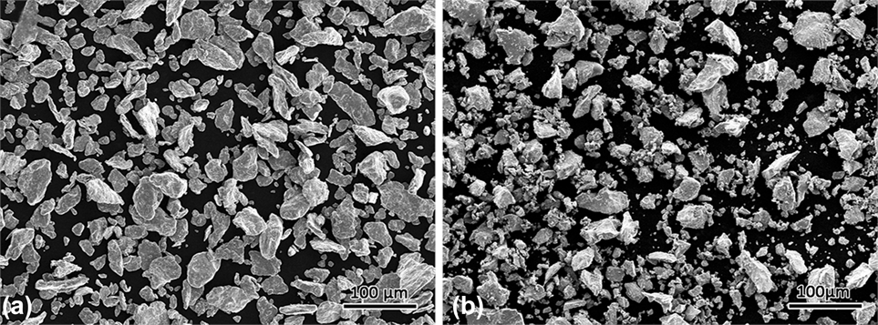
Bulk samples with the composition of Cr–18.5 at.% Nb were prepared using chromium (∼48 μm, 99.9%) and NbCr2 powders. To obtain the NbCr2 powder, bulk NbCr2 buttons were prepared by arc-melting using high purity metals (Nb: 99.99 wt% and Cr: 99.9 wt%) under a titanium-gettered argon atmosphere. The button ingots were made into powders by grinding and milling for 30 h. The average particle diameter of the sieved NbCr2 powder was measured to be about at 38 µm, which was analyzed using a laser scattering particle size distribution analyzer (LA-920, Horiba, Kyoto, Japan). The NbCr2 particles have a size distribution between 34.86 μm (D10) and 71.22 μm (D90) with mean volume (MV) diameter around 48.56 μm (D50), while the Cr particles have a size distribution between 33.04 μm (D10) and 68.06 μm (D90) with MV diameter around 46.12 μm (D50). Figure 1 summarizes the characteristics of Cr and NbCr2 powders used in the present study.
BSE images of NbCr2 (a) and Cr (b) powders showing the powder morphology.

Then, right amount of Cr powders were added into the milled NbCr2 powders to achieve the nominal composition. Prior to the SPS, the powder was mixtured in a shaker ball mill (GN-2, Shenyang Zhongbei Vacuum Tech Co., Ltd., Shenyang City, China) with a rotating speed of 200 rpm for 0.5 h. Then, the mixtures were poured into a cylindrical graphite die with an inner diameter of 20 mm. The SPS experiments were performed on a Sumitomo, Dr. Sinter, Model 1050 SPS apparatus (Sojitz Machinery Corporation, Tokyo, Japan) with a pulse pattern of 12:2 and pulse duration of 3.3 ms. The mixtures were sintered at 1473, 1573, and 1673 K for 5 min under a uniaxial pressure of 50 MPa with a heating rate of 100 K/min.
B. Microstructure characterization
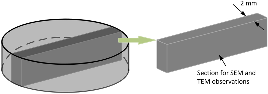
The electrodischarge machining was used to cut the samples for SEM and TEM tests. As shown in Fig. 2, the samples were taken from the cross section along the uniaxial pressure direction. A scanning electron microscope (SEM; JSM-6700F, JEOL Ltd., Tokyo, Japan) equipped with an Oxford detector was used for the electron backscattered diffraction (EBSD) measurements. The step size was 0.2 μm for all the EBSD scans. HKL Channel 5 software was used for the EBSD analyses. A transmission electron microscope (FEI Tecnai G2 F30, Hillsboro, Oregon) was used for the phase identification and high-resolution transmission electron microscopy (HRTEM) analysis. The sample was mechanically pre-thinned by hand to a thickness of less than 100 μm. Then, a dimple grinder (Model 656, Gatan Inc., Pleasanton, California) was used to thin the sample to a thickness of less than 50 μm. The final polishing was carried out on a precision ion polishing system (Model 691, Gatan Inc., Pleasanton, California).
Schematic of the cutting plane for SEM and TEM observations.

III. RESULTS
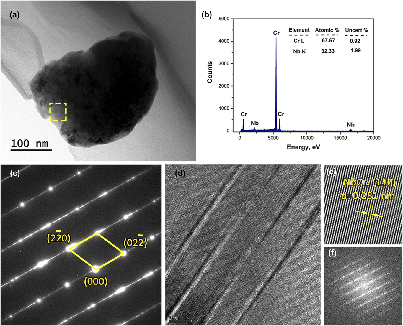
As the pre-alloyed NbCr2 powder was produced by high-energy mechanical milling, abundant distortion energy would be stored in the powders prior to SPS and would have an important effect on the sintering behaviour. The milled NbCr2 Laves phase powder needs to be examined first. Figure 3 presents the TEM micrographs along with the energy dispersive spectra (EDS), selected area diffraction pattern (SADP), and HRTEM recorded from the as-milled NbCr2 powder. With the EDS and SADP shown in Figs. 3(b) and 3(c), no other phases or oxide phases were detected, suggesting that the milled NbCr2 powders are consisted of fully NbCr2 Laves phase. However, lattice imperfections of nanotwins and stacking faults are observed in the milled powders, as indexed in Fig. 3(d). During the milling process, the increase of atomic level strain in the NbCr2 crystal lattice would activate slip and twinning, which might result in the formation of shear bands containing high densities of stacking faults and twins, as exemplified in Fig. 3(d). The distortion energy was stored in the NbCr2 powders prior to SPS mainly through the following ways: (i) severe deformation due to collisionReference Suryanarayana25; (ii) chemical short-range order may be decreased toward a random solid solutionReference Yavari26; (iii) chemical long-range order may disappear due to the vanishing of superlattice reflections; (iv) the basic topological order and fundamental unit cell of the crystal may change such as in a C14–C15 transformation.Reference Hadef27 The distortion energy stored in the milled NbCr2 powders would result in static and DRX during the subsequent SPS, and thus affect the phase and microstructure evolutions.
(a) Bright-field TEM image of the milled NbCr2 powders, (b) and (c) the corresponding EDS spectra and SADP of the area denoted in (a), respectively, (d) the HRTEM image of NbCr2 powders with corresponding IFFT (e) and FFT (f) images.

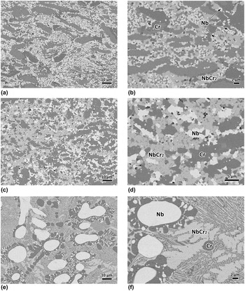
According to the existing Nb–Cr binary phase diagram,Reference Stein, He and Wossack28 the Cr–18.5 at.% Nb corresponds to the eutectic point, which should consist of fully NbCr2/Cr eutectic. Indeed, under normal solidification conditions, the Cr–18.5 at.% Nb alloy was indicated to consist of lamellar NbCr2/Cr eutectic.Reference Li, Li, Zhong, Xue and Fu29,Reference Bewlay, Sutliff, Jackson and Lipsitt30 However, the microstructures of the Nb–Cr eutectic alloy sintered in this study at different temperatures are quite unique as shown in Fig. 4. Backscatter electron (BSE) imaging indicates the Nbss and NbCr2 Laves phase as the white and gray phases embedded in the dark Cr matrix; this was confirmed using EDS. Interestingly, two novel microstructures are observed with respect to the conventionally fabricated Nb–Cr eutectic alloys, which at least consist of lamellar eutectic.Reference Li, Li, Zhong, Xue and Fu29–Reference Bewlay, Lipsitt, Jackson, Reeder and Sutliff31 At 1473 and 1573 K, the samples are consisted of elongated Cr phase along with ultra-fined NbCr2 Laves phase, Nbss (Nb solid solution), and Crss (Cr solid solution), as shown in Figs. 4(a)–4(d). The size of the interdendritic Nbss is in proportion to the sintering temperature, whereas the volume faction of Crss decreases with the sintering temperature. In addition, the elongated Cr phase was observed to distribute vertical to the load axis. As the Cr phase is softer than the Laves phase, it can deform under the load transmitted by harder phases and exhibit a kind of elongated shape oriented perpendicular to the load. However, the pressure applied SPS should have limited effect on the microstructure evolution, especially the formation of Crss and Nbss since it had been indicated that the applied pressure has little effect on the grain size, while has a marked influence on the density.Reference Munir, Anselmi-Tamburini and Ohyanagi32 A detailed discussion of the special arrangement of the Cr phase is beyond the scope of this paper, but it might be caused by the directional pulsed electric current that could lead to the formation of texture based on our preliminary research. With the sintering temperature increased to 1673 K, the microstructure evolves into coarsen NbCr2, Nbss, and Crss with lamellar structures as shown in Figs. 4(e) and 4(f).
BSE images of the Nb–Cr eutectic alloy sintered at different temperatures using Cr and NbCr2 powders: (a) and (b) 1473 K; (c) and (d) 1573 K; (e) and (f) 1673 K.

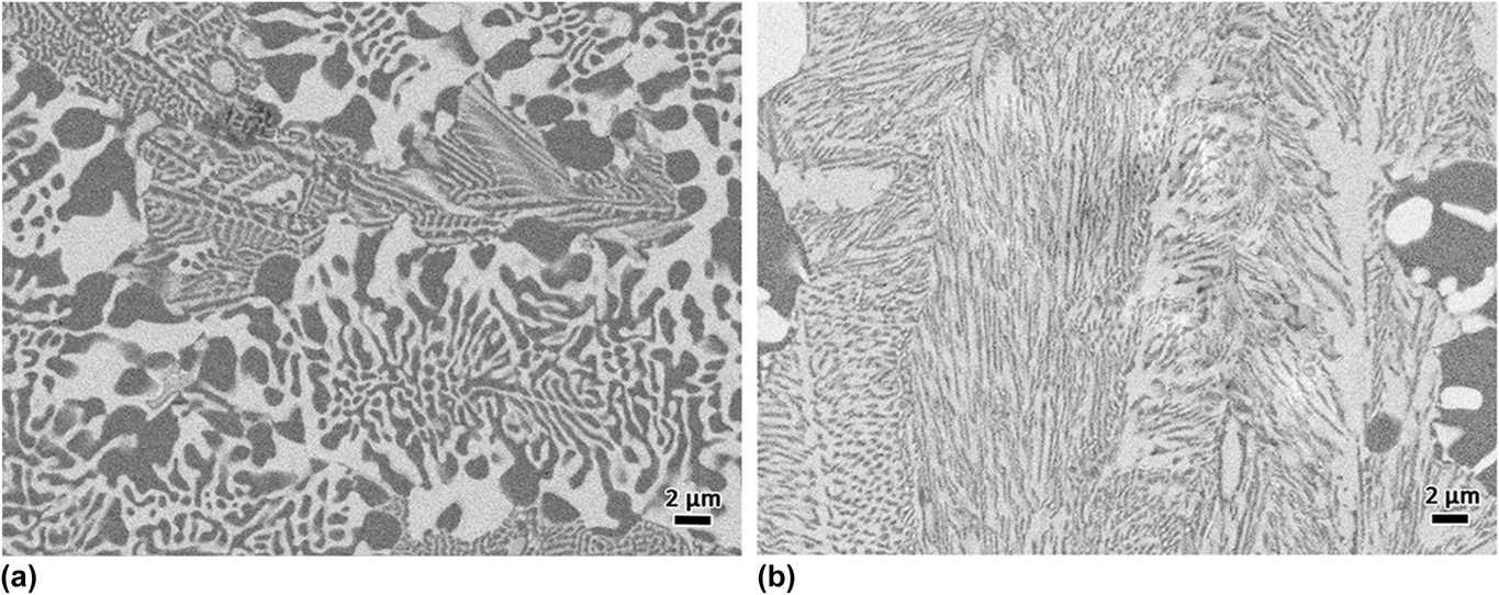
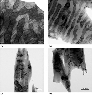
It is worth noting that there are two kinds of lamellar structures in the sample sintered at 1673 K, as shown in Fig. 5. The volume fractions of the NbCr2 Laves phase corresponding to Figs. 5(a) and 5(b) are measured to be about 50% and 65%, respectively, which are very close to the contents of NbCr2 in the Cr/NbCr2 and Nb/NbCr2 eutectics according to the phase diagram. From the TEM images illustrating in Figs. 6(a) and 6(b), it can claim that the lamellar structures presented in Fig. 4(e) are eutectics due to the good interface, while the microstructure of fine NbCr2 Laves phase and Crss shown in Figs. 4(a)–4(d) should not be eutectic as their distribution are rather disorder as shown in Figs. 6(c) and 6(d).
BSE images of the two types of eutectics present in the sample sintered at 1673 K: (a) Cr/NbCr2 eutectic; (b) Nb/NbCr2 eutectic.

Bright field TEM images of the samples sintered at different temperatures: (a) and (b) 1473 K; (c) 1573 K; (d) 1673 K.

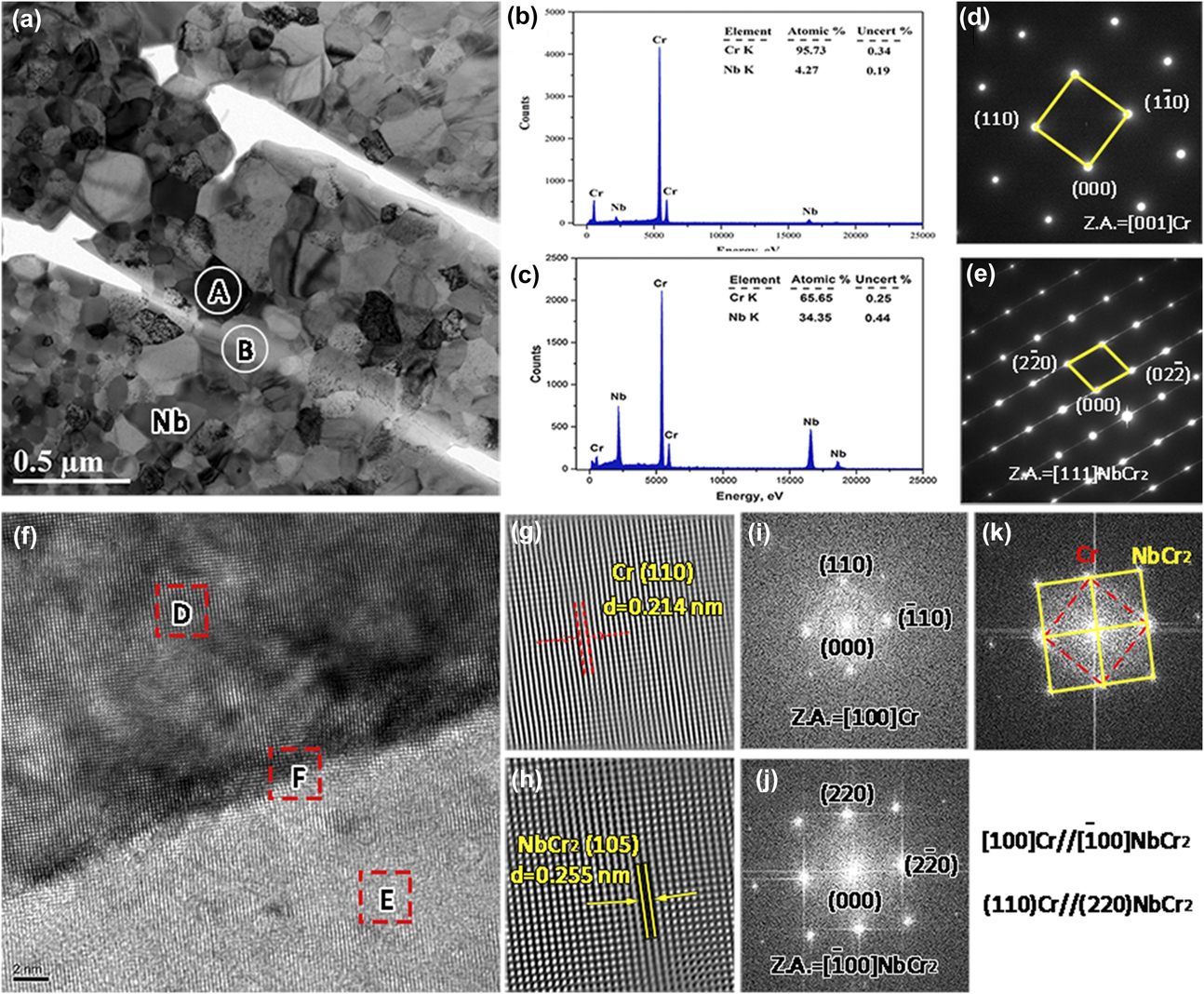
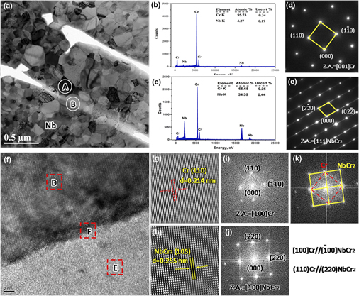
Furthermore, a strong orientation relationship between the fine Crss and NbCr2 Laves phase was detected in the samples sintered at 1573 K, as shown in Fig. 7. The EDS results presented in Figs. 7(b) and 7(c) indicate that the dark phase and light phase in Fig. 7(a) are Cr phase and NbCr2 Laves phase, respectively. Also, the corresponding SADPs shown in Figs. 7(d) and 7(e) are indexed as Cr and NbCr2 Laves phase, respectively. Meanwhile, the HRTEM image and the corresponding fast Fourier transformation (FFT) as well as the inversed fast Fourier transformation (IFFT) patterns shown in Figs. 7(f)–7(k) suggest that the Cr phase exhibited a strong orientation relationship with the NbCr2 Laves phase. The orientation relationship was ascertained to be as follows:
 $${\left[ {011} \right]_{{\rm{Cr}}}}//{\left[ {0\bar{1}\bar{1}} \right]_{{\rm{NbC}}{{\rm{r}}_2}}}\;{\rm{and}}\;{\left( {1\bar{1}0} \right)_{{\rm{Cr}}}}//{\left( {2\bar{1}2} \right)_{{\rm{NbC}}{{\rm{r}}_{\rm{2}}}}}\quad .$$
(a) Bright field TEM image of the sample sintered at 1573 K, (b) and (c) the EDS spectra of the areas A and B denoted in (a), respectively, (d) and (e) the corresponding SAED patterns of areas A and B denoted in (a), respectively, (f) HRTEM of the area NbCr2/Cr interface in (a), (g), and (h), the IFFT images of areas D and E denoted in (f), respectively, (i), (j), and (k) the FFT images of areas D, E, and F denoted in (f), respectively.

In the as-cast condition, the Cr phase and NbCr2 Laves phase did not show any orientation relationship.Reference Bewlay, Sutliff, Jackson and Lipsitt30 A strong orientation relationship was considered to be beneficial to the mechanical properties. It has been reported that an interface phase could be formed between the Laves phase and BCC solid solution in Laves phase related BCC solid solution alloy during the SPS process.Reference Pei, Song, Liu, Zhao and Chen33 The maximum hydrogen storage capacity of this alloy was increased by 24% compared with the arc melting alloy. In addition, the NbCr2 Laves phase exhibited little imperfections of twins and dislocations. This is quite different to the other Laves phase alloys processed by traditional methods. In the binary Cr/Cr2Nb, Cr/Cr2Ta, and Cr/Cr2Zr, a multitude of faults have been detected in the Cr2Nb, Cr2Ta, and Cr2Zr Laves phases.Reference Kumar, Pang, Horton and Liu34,Reference Kumar, Pang, Liu, Horton and Kenik35
IV. DISCUSSION
As described above, a series of phase evolutions along the sintering temperature occurred when sintered with pre-alloyed NbCr2 and Cr powders. Moreover, the fine Crss shows a strong relationship with NbCr2 Laves phase in the samples sintered at 1473 and 1573 K. In this case, the emphasis is focused on the phase morphological and microstructural evolution of the NbCr2 Laves phase during SPS.
As previously reported, a temperature increase will be created in the particles when the pulsed electric current passes through,Reference Song, Liu and Zhang36 and the temperature increase can be written as
 $$\Delta T = {{256} \over {{\pi ^2}}} \cdot {{I_{\rm{p}}^{\rm{2}}{r^4}\rho \Delta t} \over {{C_{\rm{v}}}{\rho _{\rm{m}}}{\varphi ^4}{{\left[ {{r^2} - {{\left( {r - x} \right)}^2}} \right]}^2}}}\quad ,$$
where Δt is the duration of pulsed current, ρ is the resistivity, ρm is the theoretical density, C v is the specific heat, φ is the inner diameter of the die, r is the particle size, I p is the local intensity of the current passing through the two particles, which can be estimated as
 $${I_{\rm{p}}} = {{4{r^2}} \over {{\varphi ^2}}}{I_{\rm{s}}}\quad ,$$
where φ is the diameter of the sample and I s is the intensity of the output current pass though the sample:
 $${I_{\rm{s}}} = {I_{\rm{T}}}{{{1 / {{R_{\rm{s}}}}}} \over {{1 / {{R_{\rm{d}}}}} + {1 / {{R_{\rm{s}}}}}}} = {I_{\rm{T}}}{{{\rho _{\rm{d}}}{S_{\rm{s}}}} \over {{\rho _{\rm{s}}}{S_{\rm{d}}} + {\rho _{\rm{d}}}{S_{\rm{s}}}}}\quad ,$$
where I T is the total input current intensity, S s and S d are the cross-sectional areas, and ρs and ρd are the resistivities of the sample and die, respectively. The main difference in temperature distribution calculation between pure metals and binary alloys is the resistivity. For the binary Cr/NbCr2 alloy, the resistivity of the Cr phase is not equal to that of the NbCr2 phase, while the difference should be smaller than one order of magnitude. Thus, this equation can be used to calculate the temperature distribution in dual phase alloys. As the resistivity of NbCr2 is unknown, the accuracy of theoretical calculation cannot be guaranteed. We calculate the temperature distribution in the powder by using the parameters of Cr metal. As the resistivity of NbCr2 powder should be larger than Cr powder due to the existence of ionic bond in the intermetallic compound, the calculated temperature increase should be a little smaller than the real value when calculated with the parameters of Cr metal.
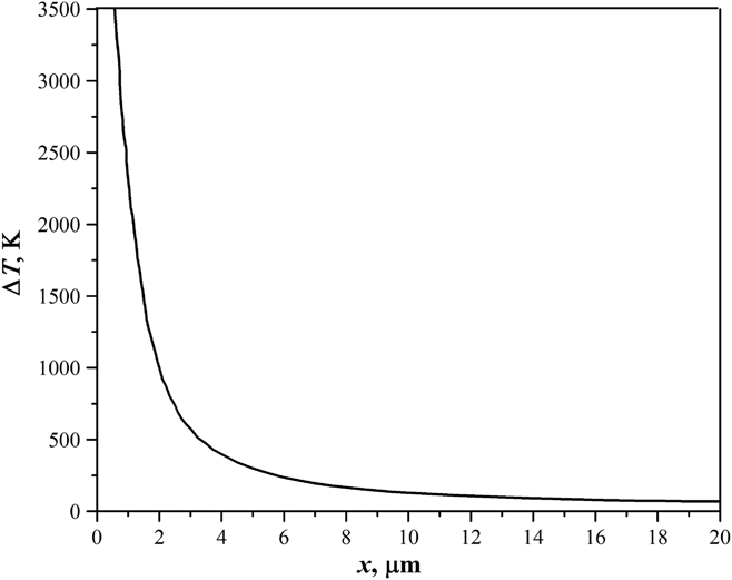
Figure 8 shows the calculated temperature distribution by substituting the parameters listed in Ref. Reference Li, Li, Gao and Gong24. It can be seen that there is a considerable temperature distribution in the particle-contacting surface, while the temperature increase at the center of powder particles is rather limited. The temperature at the particle-contacting region may even reach the boiling point of the powder, which would result in a local melting at the surfaces of the NbCr2 and Cr powders. The inhomogeneous temperature distribution would have an important influence on the phase evolution and microstructure formation.
The calculated temperature distribution during SPS.

As shown in Figs. 4(b) and 4(d), the size of the Nbss phase increases with the sintering temperature, whereas the size of Crss decreases with the sintering temperature. With higher sintering temperature, the newly formed Nbss has a greater tendency to grow, which would result into the formation of the coarser Nb phase. While, more Cr powders would react with the milled NbCr2 powders at higher sintering temperature, which would cause the quantity reduction of the residued Crss phase.
In addition to the local melting, the milled NbCr2 powders would experience a recrystallization due to the stored distortion energy. In this case, abundant grain boundaries would be generated in the milled NbCr2 powders. The locally melted Cr would permeate into the grain boundaries and divide the NbCr2 powders into many small blocks. Moreover, the atomic diffusion in the melt can be significantly accelerated by the pulsed electric current applied during SPS. The diffusion flux with pulsed electric current can be evaluated by the following equationReference Munir, Anselmi-Tamburini and Ohyanagi32:
 $${J_i} = - {{{D_{{\rm{ie}}}}{C_i}} \over {RT}}\left[ {{{RT\partial \ln {C_i}} \over {\partial x}} + F{z^ * }E} \right]\quad ,$$
where J i is the flux of the diffusing i th species, D ie is the diffusivity of the species, C i is the concentration of the species, R is the gas constant, T is the temperature, F is Faraday’s constant, z* is the effective charge on the diffusing species, and E is the field. It is seen that the applied pulsed electric current can not only create an extra term but also alter the diffusivity. The diffusivity D ie with pulsed electric current can be expressed asReference Tu, Yeh, Liu and Chen37
 $${D_{{\rm{ie}}}} = {D_0}\exp \left( { - {{Q - {Q_{\rm{e}}}} \over {kT}}} \right) = {D_0}\exp \left( { - {{Q - {Q_{\rm{e}}}} \over {RT}}{N_{\rm{A}}}} \right)\quad ,$$
where D 0 is the temperature independent factor; Q is the activation energy; k is the Boltzmann constant, T is the temperature, N A is the Avogadro constant, A 1 is the constant, and Q e, associated with electromigration, is given byReference Tu, Yeh, Liu and Chen37
 $${Q_{\rm{e}}} = A\left| {{z^ * }} \right|e\rho 'j\quad ,$$
where A is a constant, e is the charge of an electron, ρ′ is the resistivity, and j is the current density. In this case, the diffusion coefficient D ie with a pulsed electric current can be expressed as
 $${D_{{\rm{ie}}}} = {D_0}\left( { - {{Q'} \over {kT}} + {{{A_1}\left| {{z^ * }} \right|e\rho 'j} \over {RT}}} \right)\quad ,$$
where Q′ is the activation energy for a mole of atoms. The pulsed electric current can influence the activation energy of atoms by providing an additional driving force for atomic diffusion due to electromigration resulting from the collision between electron wind and metal ions.
With the enhanced atomic diffusion in the local melt, the nucleation behavior would be altered and thus affect the phase selection and microstructure evolution. The nucleation rate (I e) can also be enhanced with pulsed electric current,Reference Liu, Fan, Zhang, Jin, Dong and Xu38
 $${I_{\rm{e}}} = {I_0}\left( {{{{D_{\rm{i}}}} \over {{\lambda ^2}}}} \right) \cdot \exp \left( { - {{\Delta {G^0} + \Delta {G^{\rm{e}}}} \over {RT}}} \right)\quad ,$$
where I 0 is a constant, λ is the jump distance, D i is the diffusivity, R is the Boltzmann constant, T is the absolute temperature, ΔG d is the deformation stored energy, and ΔG e is an additional term in comparison with the system without electric current. It can be seen from Eq. (8) that the nucleation rate can be enlarged by the applied pulsed electric current, and thus facilitating the formation of nonequilibrium phases.
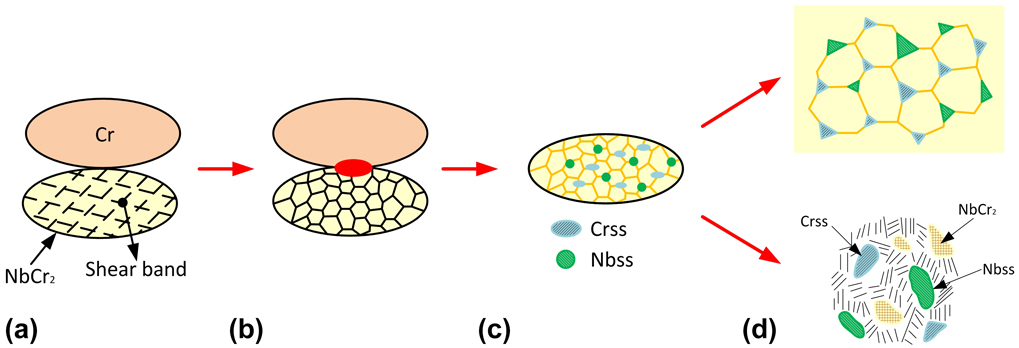
From Eqs. (2) and (8), both the mass transport and nucleation rate at the particle-contacting zone can be significantly enhanced due to the large temperature increase and the accelerated atomic diffusion. Thus, the melts can quickly attain intermediate compositions between NbCr2 and Cr elements. During the subsequent solidification process, Crss and NbCr2 Laves phase can precipitate from the particle-contacting zone according to the phase diagram. This will also facilitate the nucleation of Crss and Nbss at the shear bands as shown in Fig. 9(a). During the SPS, the milled NbCr2 powders would experience a DRX, as shown in Fig. 9(b). Thus, some Crss and Nbss blocks are observed to appear in the microstructures, as shown in Fig. 9(c). Moreover, the size of Nbss increases with the sintering temperature due to grain growth. While for the sample sintered at 1673 K, the thickness of the melt layer is increased with respect to the other two samples. With the growth of the precipitated Crss and Nss, the local composition would be altered and thus promote the formation of eutectics, as shown in Fig. 9(d). The formation of Crss and Nbss as well as the residual of coarse Cr phase is believed to be effective in hindering the propagation of cracks initiated from the NbCr2 Laves phase and thus are expected to markedly improve the room temperature fracture toughness.
Sketch illustrating the formation of Nbss, Crss, and NbCr2 Laves phase when sintered with Cr and NbCr2 powders: (a) prior to SPS; (b) the formation of local melting and DRX of NbCr2 powder; (c) the nucleation of Crss and Nbss; (d) the growth of Crss and Nbss.

In addition, the morphology of the newly formed Crss in the sample sintered at 1673 K is basically circular, which is quite different to that formed in the samples sintered at 1473 and 1573 K. However, it is still hard to say if there are some newly formed Crss in the samples sintered at 1473 and 1573 K. In theory, at least, both the Crss and Nbss have the potential to nucleate in the samples sintered at 1473 and 1573 K because the temperature at the particle contacting region is high enough to cause local melting. With the applied pulsed electric current, new nucleus of Crss and Nbss can be formed. Further work with respect to this issue is still needed. Controlling the formation of Crss and Nbss can provide benefits for the mechanical properties optimization, and further work is needed to assess the formation of Crss in lower sintering temperatures.
V. CONCLUSION
Bulk NbCr2 Laves phase matrix composites toughened with ductile Cr phase have been fabricated by SPS using pre-alloyed NbCr2 and Cr powders. Along the sintering temperature, a series of phase evolutions occurred: elongated Cr phase with uniform dispersion of fine NbCr2 and Cr phase → coarse Cr phase with matured fine NbCr2 and Cr → coarse Cr and Nb phases with lamellar eutectics. The phase morphological and microstructural evolution of the Nb–Cr eutectic alloy are analyzed by considering the inhomogenous temperature distribution and the accelerated atomic diffusion due to the applied pulsed electric current during SPS. The relatively high temperature and rapid atomic diffusion at the particle contacting area would facilitate the nucleation of Crss and Nbss at the shear bands of the NbCr2 Laves phase. Moreover, the size of Nbss increases with the sintering temperature due to grain growth. Increasing the sintering temperature to 1673 K, the thickness of the melt layer is remarkedly increased and thus facilitates the precipitation of eutectic.
ACKNOWLEDGMENTS
This work was supported by the National Natural Science Foundation of China under Grant No. 51604190 and the State Key Laboratory of Solidification Processing in NWPU under Grant No. SKLSP201824.