1. INTRODUCTION
Function modeling (FM) is the name given to the activity of developing models of devices, products, objects, and processes based on their functionalities and the functionalities of their subcomponents. Researchers acknowledge that developing such a high-level representation scheme provides useful facilities. These include an overall system description to facilitate the communication and understanding between engineers of various disciplines and means to make use of computers for reasoning purposes. The basic concern of FM is how to represent knowledge about function. The representation framework is important to serve as a general and common communication framework on the one hand and to facilitate the use of automated reasoning systems on the other hand.
FM constructs a basis for solving the representation problems of complex products and their complex development processes. The complexity in product development is a result of both the interdisciplinarity in the process and the physically, geographically, and temporally distributed nature of design teams (Szykman et al., Reference Szykman, Raez, Bochenek and Sriram2000, Reference Szykman, Fenves, Keirouz and Shooter2001; Tomiyama & Meijer, Reference Tomiyama, Meijer, ElMaraghy and ElMaraghy2005). As Szykman et al. (Reference Szykman, Raez, Bochenek and Sriram2000) state, “a single designer or design team can no longer manage the complete product development effort.” FM provides a framework for overall system description. The barriers between the subdisciplines can be overcome by using its common language of functionality. By supporting decomposition of functionalities, FM bridges the gap between the high-level requirements and the low-level details. Such a common model provides a holistic view of the system above the domains of different expertise and makes it possible to go back and forth in the design process to check the satisfaction of high-level requirements by the lower level specifications.
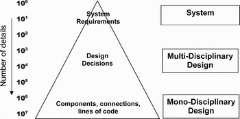
The conventional design processes, concerning both applications in industry and education of engineers, seem to promote one-way, top-down procedures, starting from the requirements going toward their realization. Because of the top-down nature of the procedures little iteration is performed between the design steps. After a decomposition process the high-level view of requirements is translated into low-level detailed component specifications. This is illustrated in Figure 1 (Muller, Reference Muller2007). The small number of statements at the top of the pyramid finally results in millions of details in the technical product description. The proliferation of details creates a gap of communication between the upper and lower levels. The requirement designers in the upper levels lose their grasp of what is performed in the lower levels, but the component designers in the lower levels miss the aim of their own work within the overall system. FM serves as a means of linking the upper and lower levels of system design and description. Therefore, it can be placed in the middle of the pyramid, in the multidisciplinary section in Figure 1.
An adaptation of the device pyramid of design according to Muller (Reference Muller2007). Adapted with permission of the author.

Referring to Figure 1, the transition from multidisciplinary design view to monodisciplinary subdesign problems usually follows the division of the conventional engineering disciplines like mechanical, electrical, and software. The separation of disciplines is more or less a consequence of the engineering education programs still anchored to a single domain (Rault, Reference Rault and Scintilla1992). The laws of physics in relation to a single product, however, are not always compatible with the separation of disciplines. Many phenomena that can be categorized in different engineering disciplines have strong physical interrelations (Tomiyama, Reference Tomiyama, Gu, Xue, Ramirez-Serrano, Park and Fletcher2006; Tomiyama & D'Amelio, Reference Tomiyama, D'Amelio and Krause2007a, Reference Tomiyama and D'Amelio2007b). Therefore, engineers of different disciplines working in the same design team have to communicate and cooperate with each other on various issues. But the solution to “how to bridge the multitude of models required to support a complex design” (Wang et al., Reference Wang, Shen, Xie, Neelamkavil and Pardasani2002) is not trivial. FM, being a common representation framework above the single domains, provides means of communication among the engineers of different disciplines. In this sense, FM does not only serve for vertical linking between the upper and lower levels, but also for horizontal communication within the lower levels in Figure 1.
In the second section, a review of FM approaches is given. This review is performed with the intention of building a general frame for FM as an intermediate category between the realms of human needs and objects. In the third section, the relation of FM with the research fields of artificial intelligence (AI), design theory and product development, and maintenance are discussed. In this section a review of implementation of FM approaches and the resultant computer-aided design (CAD) tools is also given by mentioning their reasoning mechanisms. In the fourth section, the ongoing research in the Intelligent Mechanical Systems Group is introduced by making use of the general FM frame. The aim is both to show the applicability of such a frame for different problem domains and to delineate the common denominator of the mentioned research efforts on the basis of FM. The basic concepts of these efforts, namely, evolvability, unpredicted interferences, intelligent maintenance, and service design are outcomes of the particular way of thinking with FM. The fifth section concludes the paper.
2. REVIEW OF FM APPROACHES
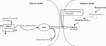
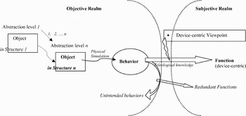
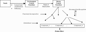
In this section, a review of FM approaches is presented based on the FM-oriented papers among the references. Specifically, the approaches for developing functional concept ontologies (Kitamura et al., Reference Kitamura, Kashiwase, Fuse and Mizoguchi2004) are detailed. The references that are not directly FM oriented are only mentioned whenever they are relevant. A generalized framework of FM is graphically represented in Figures 2–4. This framework is mainly based on the descriptions of Chandrasekaran and Josephson (Reference Chandrasekaran and Josephson2000), but it has been extended with the descriptions of other studies. The similarities and differences between the conceptions of Chandrasekaran and Josephson (Reference Chandrasekaran and Josephson2000) and other scholars are mentioned.
The environment-centric view of function modeling.

The device-centric view of function modeling.

Relations between needs, functions, and design object.

2.1. Function and functional ontology
A functional model shows how the general goal of a system is achieved by realization of subgoals via the subfunctions in the system. Quoting Kitamura et al. (Reference Kitamura, Kashiwase, Fuse and Mizoguchi2004), “functional models represent a part of (but not all of) the designer's intentions, so called design rationale.” A similar approach is implicitly used in other applications that are not directly FM oriented, such as failure mode and effect analysis (FMEA; Klein & Lalli, Reference Klein and Lalli1989; Rausand & Oien, Reference Rausand and Oien1996) and fault tree analysis (FTA; Lee et al., Reference Lee, Grosh, Tillman and Lie1985). However, the representation framework of those is noted to be task specific (Kitamura et al., Reference Kitamura, Kashiwase, Fuse and Mizoguchi2004). In contrast, FM needs generalized frameworks to support ease of description and knowledge retrieval in different domains. The framework that provides the viewpoints and the necessary vocabulary to represent functional knowledge is called a functional ontology (Kitamura & Mizoguchi, Reference Kitamura and Mizoguchi2003; Kitamura et al., Reference Kitamura, Kashiwase, Fuse and Mizoguchi2004).
It is possible to distinguish three domain ontologies intended to model and describe engineering products. Among those, device ontology regards a device or a system to be composed of black box modules connected with input–output relations. Device ontologies define agents of a system that process their own input data and produce outputs to be transferred to the other agents. The qualitative physics proposed by de Kleer and Brown (Reference De Kleer and Brown1984) is an example of device-centered ontology for artifacts. In addition, the design approach of Pahl and Beitz (Reference Pahl and Beitz1988), known as the German systematic design approach, makes use of the device-centered ontology (Kitamura et al., Reference Kitamura, Kashiwase, Fuse and Mizoguchi2004).
In the process ontology approach the focus is on the processes, rather than the components. Therefore, in process ontology there are no agents, but participants in the processes. The attributes of the entities are regarded as changing not as a result of their input–output relations, but as a consequence of the effect of processes (Kitamura & Mizoguchi, Reference Kitamura and Mizoguchi2004). The qualitative process theory (QPT) developed by Forbus (Reference Forbus1984) is the pioneering example of process ontology development.
The functional concept ontology, which is the basic concern of this paper, aims at developing a model of a device/system from a teleological point of view (de Kleer & Brown Reference De Kleer and Brown1984; Kitamura & Mizoguchi, Reference Kitamura and Mizoguchi2003, Reference Kitamura and Mizoguchi2004). Namely, FM seeks to develop a model based on the questions of what the device and its components do or what the purpose of the device and its components are. The functional concept ontology aims at developing the necessary framework and language to model the functionality of a system from the subjective viewpoint of human (the designer, user, or developer). Among others, the work of Chandrasekaran and Josephson (Reference Chandrasekaran and Josephson2000), Umeda et al. (Reference Umeda, Ishii, Yoshioka, Shimomura and Tomiyama1996), Umeda and Tomiyama (Reference Umeda and Tomiyama1995), Yoshioka et al. (Reference Yoshioka, Umeda, Takeda, Shimomura, Nomaguchi and Tomiyama2004), Gero (Reference Gero1990), Kitamura and Mizoguchi (Reference Kitamura and Mizoguchi2004), and Keuneke (Reference Keuneke1991) are attempts to build functional ontologies.
Function is considered by Umeda and Tomiyama (Reference Umeda and Tomiyama1995) as a bridge between human intention and physical behavior of artifacts. The authors state “there is no clear and uniform definition of a function, and moreover, it seems impossible to describe function objectively.” The subjective character of function and its being an intermediate between intentions and objects are acknowledged by many other FM researchers including Chandrasekaran and Josephson (Reference Chandrasekaran and Josephson2000), Deng et al. (Reference Deng, Britton and Tor2000), Keuneke (Reference Keuneke1991), and Balachandran and Gero (Reference Balachandran, Gero and Gero1990). However, in the literature there are conceptions of function that do not or partially share the idea of subjectivity. In these approaches functions are directly matched to some physical objects or components. In other words, functions are used no more than as labels for physical structures. Rodenacker (Reference Rodenacker1971) defines function as a relationship between input and output of energy, material, and information, and this definition is widely accepted in design research (Pahl & Beitz, Reference Pahl and Beitz1988; Welch & Dixon, Reference Welch, Dixon, Taylor and Stauffer1992). The functions defined by Pahl and Beitz (Reference Pahl and Beitz1988), although they share the idea of subjectivity to some extent, are considered to be too abstract to describe details of intentions (Kitamura et al., Reference Kitamura, Kashiwase, Fuse and Mizoguchi2004). Bracewell and Sharpe (Reference Bracewell and Sharpe1996) represent functions based on extending the bond graph technique (Rosenberg & Karnopp, Reference Rosenberg and Karnopp1983), which introduces the concepts of “flow” and “effort to cause a flow” in the system. Value engineering represents function in the form of “to do something” (Miles, Reference Miles1972). This representation as “verb + noun,” which again shares subjectivity to some extent, is noted to be incapable of avoiding inappropriate modeling (Kitamura et al., Reference Kitamura, Kashiwase, Fuse and Mizoguchi2004). In this paper, basically the conceptions of Umeda et al. (Reference Umeda, Ishii, Yoshioka, Shimomura and Tomiyama1996), Umeda and Tomiyama (Reference Umeda and Tomiyama1995), and Chandrasekaran and Josephson (Reference Chandrasekaran and Josephson2000) are followed. Function is considered as a subjective category that links the human intentions/purposes residing in the subjective realm to the behaviors and structures in the objective realm.
2.2. Function as an intermediate concept between needs and objects
This section gives an account of the concept of function from the semantics point of view. The concepts of function, behavior, structure, and their relation with the human needs are elaborated with the understanding of the division of subjective and objective realms, as indicated in Figures 2 and 3. The subjective realm corresponds to the mental conceptions and the mental planning, also named as mental simulation, of humans. These are performed on an abstract level, without consideration of the exact physical interactions. The phase of conceptual design in the design process, for example, takes place in this realm. In contrast, the objective realm corresponds to the physical relations and processes that apply to the object.
Chandrasekaran and Josephson (Reference Chandrasekaran and Josephson2000) identify two viewpoints of function. In the “environment-centric viewpoint,” function is a matter of the effect of the object on the environment in which it is placed (Fig. 2). The function from environment-centric viewpoint is called “function as effect.” In the “device-centric viewpoint” the function, which is called “function in device-centric terms,” is a matter of internal parameters of the object (Fig. 3). Chandrasekaran (Reference Chandrasekaran2005) mentions a priority between the two views. Function as effect is achieved as a result of the combination of the function in device-centric terms and the “mode of deployment” of the object (Fig. 4).
In the environment-centric view (Fig. 2), the intentions of human are linked to the objects via the realm of functions. The human needs undergo a few stages of “abstraction levels” (Chandrasekaran & Josephson, Reference Chandrasekaran and Josephson2000). The function that is related to the objective realm is defined in the last abstraction level. The object itself is placed in the objective “world” in a particular manner, which is conceptualized as a particular “mode of deployment.” Depending on its mode of deployment, the object realizes some “roles” in the world it is placed. The object, the mode of deployment, and the roles take place in the objective realm and are immune from the intent of human. It is when some of the roles of the object are recognized as functions as effect that the contact with the objective and subjective realms is maintained.
In the device-centric view (Fig. 3), the focus is not on the effect of the object on its environment, but on its internal configuration, namely, on its structure (Chandrasekaran & Josephson, Reference Chandrasekaran and Josephson2000). It is possible to identify different structures for the same objective system in different abstraction levels. For instance, it is possible to consider a calculator both as a structure of electrical circuits composed of transistors and as a structure of logic operation system composed of adders, logic gates, and so forth. Based on the abstraction level of the structure, some behaviors are observed with the object. Structure, abstraction level, and behaviors all take place in the objective realm. Some of the behaviors realized by the object are recognized as functions in the subjective realm.
The function–behavior–structure (FBStr)Footnote 1 model developed by Gero (Reference Gero1990) defines function as an intermediate between the goal of human and the behavior of a system. The focus of the FBStr model is more on the design process, which is considered to be a transformation from intentions to the structure. In Balachandran and Gero (Reference Balachandran, Gero and Gero1990), the authors define function, structure, and behavior as three classes of properties of a design object: “Function properties dictate its intended purpose, requirements, structure properties represent the description of the whole and its constituents, while the behavior properties spell out how the structure of the object achieves its function.” There are some behaviors of the object that realize the intended functions. Those behaviors are derived from the intended functions by making use of “teleological knowledge” (Fig. 3). This means that the selection of behaviors associated with the intended function is not explained by the physics underlying the behaviors, but by their consequences that are useful for the intentions. However, the actual physics underlying the behaviors result in behaviors other than the ones determined by the teleological knowledge. The difference between the set of all behaviors realized by the structure and the expected behaviors is named as unintended behaviors in Figure 3. Dorst and Vermaas (Reference Dorst and Vermaas2005) provide a detailed analysis of various papers of Gero and colleagues about the FBStr in order to identify the ambiguities of the model described in different papers.
In the function–environment–behavior–structure (FEBS) design model (Deng et al., Reference Deng, Tor and Britton1999, Reference Deng, Britton and Tor2000; Tor et al., Reference Tor, Deng and Britton1999; Deng, Reference Deng2002), “the working environment” signifies the environmental elements that contribute to the functions of the design. This conception is analogous to the conception of mode of deployment of Chandrasekaran and Josephson (Reference Chandrasekaran and Josephson2000), as indicated in Figure 2. “The physical structure” in FEBS signifies the object of the design. Similar to Balachandran and Gero (Reference Balachandran, Gero and Gero1990), the authors mention that an object exhibits many behaviors not necessarily recognized as functions. Among those, the ones associated with the intended functions are called “the intended behaviors.” The authors argue that only the intended behaviors need to be considered in the functional design process. In their scheme a function is defined by specifying the set of physical structures (objects) necessary to achieve it.
The environment-centric function is an intermediary step between the needs and the device-centric function (Fig. 4; Chandrasekaran & Josephson, Reference Chandrasekaran and Josephson2000). The needs are defined as functions when the possible lowest level of abstraction is achieved for their expression. For example, the illuminating function of a reading lamp is reached not directly from the need to read but after some transformations: the need to read is transformed into the need to illuminate the paper, and then the need to illuminate with proper lighting, and so forth. The environment-centric function of illuminating the paper is transformed into the device-centric function of “turning the light on when pushed on the button” via the specific mode of deployment, according to which a reading lamp is used in a room. This deployment dictates that the lamp should be turned on and off with the control of a button, the button should be close to the reading place, and so forth. Chandrasekaran (Reference Chandrasekaran2005) states the mapping between the needs and artifacts is a many to many mapping. This means an artifact can fulfill more than one need, as well as a need can be fulfilled by more than one artifact. For example, a lamp can fulfill the function of heating, in addition to providing light. Obviously, using a lamp is an inefficient way of satisfying the need of heating. Therefore, Chandrasekaran and Josephson (Reference Chandrasekaran and Josephson2000) mention the expression of needs as an environment-centric function should not only be in the lowest level of abstraction but also consider the efficient fulfillment of the need.
Once the need of humans is formulated as a device-centric function, the task is to decompose this function into subfunctions that can later be associated with some physical phenomena and components of the design object (Fig. 4). Umeda and Tomiyama (Reference Umeda and Tomiyama1995) suggest that the decomposition procedure be performed not through a single top-down direction but following a top-down–bottom-up approach simultaneously. Although the top-down process decomposes the functions into subfunctions, a bottom-up process results in the recognition of high-level functions from the lower level subfunctions. The decomposition is followed by the embodiment process, which instantiates the undecomposable functions with physical features (Umeda et al., Reference Umeda, Ishii, Yoshioka, Shimomura and Tomiyama1996). Association of the physical features with object components and integration of the components result in the actual design object.
2.3. Function and structure, mental simulation, and behavioral simulation
Keuneke (Reference Keuneke1991) considers functional representation as a means of constructing a new organizational structure. The actual physical structure of the system that resides in the objective realm corresponds to the visible topology, in which physical simulation can be performed. Qualitative physics, for example, can be used to simulate the physical structure. However, what is needed in the design phase is, in fact, a mental simulation, which tests if the design corresponds to the human needs. Functional representation transforms the behaviors in the physical structure into the realm of functions. A mental simulation is possible within the new organization achieved with functions. Keuneke (Reference Keuneke1991) defines explicitly four types to capture all possible functions: ToMake, ToMaintain, ToPrevent, and ToControl.
Far and Elamy (Reference Far and Elamy2005) consider functions as means of switching from model-based reasoning (MBR) technology to functional reasoning technology. Whereas MBR technology deals with “what a device does,” the functional reasoning technology deals with “what a device is for.” This understanding is very close to the understanding of the separation of objective and subjective realms. Whereas MBR takes place in the objective realm, functional reasoning takes place in the subjective realm.
In their function–behavior–state (FBS) model Umeda, Tomiyama, and colleagues (Umeda et al., Reference Umeda, Takeda, Tomiyama and Gero1990, Reference Umeda, Tomiyama and Yoshikawa1995a, Reference Umeda, Ishii, Yoshioka, Shimomura and Tomiyama1996, Reference Umeda, Kondoh, Shimomura and Tomiyama2005; Umeda & Tomiyama, Reference Umeda and Tomiyama1995, Reference Umeda and Tomiyama1997) develop a function representation in which the subjective and objective realms are related to each other with function–behavior relationship. The authors define the function as “a description of behavior recognized by a human through abstraction in order to utilize it.” They argue that it is difficult to disassociate function from the behavior; therefore, they represent function as a tuple in which both the human intention (function as to do something) and physical semantics (behavior) are represented. In this way they come up with a representation through which the subjective selection of some behaviors as a function is formalized. The objective realm is placed in a framework that they call an “aspect.” This aspect corresponds to the abstraction level, or, with their terms, “physical situations of the current interests” (such as the discipline of electrical or mechanical engineering), in which the entities, attributes, relations, and physical phenomena are defined in a particular way. (In Umeda et al., Reference Umeda, Takeda, Tomiyama and Gero1990, the authors use the term “view” instead of “aspect” with the same meaning.) The authors state that the selection of these views is subjective, and it affects the choice and decomposition of functions. The authors (Umeda & Tomiyama, Reference Umeda and Tomiyama1995) mention that their representation of function is less formal than that of Keuneke (Reference Keuneke1991), in the sense of being applicable to a wider range of functions including the ones that cannot be grasped by the latter's four types.
The physical phenomena taking place in the aspect results in the change of states of the system. A state corresponds to a particular set of entities, attributes of entities, and relations between entities. In Umeda et al. (Reference Umeda, Takeda, Tomiyama and Gero1990) the authors argue there is no meaningful distinction between state and structure. They claim the difference between the two in conventional usage is just a matter of duration: structures that change in a short time are generally called states. Therefore, they adopt the term state rather than structure in their FBS model, with the intention of covering both meanings in conventional usage. Sequences of one or more changes of states correspond to behaviors that take place in the objective realm. A behavior is therefore defined as a sequential change of states over time. As mentioned before, some of the behaviors taking place in the objective realm are recognized as functions in the subjective realm.
The structure–behavior–function (SBF) model developed by Goel and colleagues (Goel & Chandrasekaran, Reference Goel and Chandrasekaran1989, Reference Goel, Chandrasekharan, Tong and Sriram1992; Goel, Reference Goel1991) considers behavior as an intermediate concept between the structure and subjectively defined functional requirements (FRs). The structure in the modeling of SBF is composed of the components and the substances in the system. The substances in the system are defined by their location with respect to the components and the behavioral properties they have. The structure is represented as a hierarchy of these components, substances, and their relations. The relations are expressed with terms such as “part-of,” “includes,” and “parallelly connected” (Goel & Bhatta, Reference Goel and Bhatta2004). The behaviors in the SBF model are the concepts that are used to explain the realization of the functions with the concrete structural elements in the device. They can be considered as descriptions of what a component in the structure does. In this sense, behaviors are intention independent. Behaviors are represented as sequences of transitions between behavioral states. A function in the SBF model is an abstraction of behaviors, associated with an input–output relation. The behavioral states that realize the function are considered to be the input of the function. The behavioral states that are produced by the realization of the function are considered to be the outputs. In this scheme the subjective category of function can be considered to be a hypothetical link between structural behavioral states (Bhatta et al., Reference Bhatta, Goel and Prabhakar1994; Goel & Bhatta, Reference Goel and Bhatta2004).
2.4. No function in structure principle
The no function in structure principle proposed by de Kleer and Brown (Reference De Kleer and Brown1984) is intended for developing functional models of devices based solely on the functionalities of their components. The principle states that the descriptions of the behavior of any constituent part of a system should not refer to how the overall system functions. De Kleer and Brown (Reference De Kleer and Brown1984) aim to describe the behavior of a system based on the generic models of its components that are potentially listed in a model library. Such an understanding is claimed to ease the modular operation and replacement of any functional component (de Kleer & Brown, Reference De Kleer and Brown1984). Keuneke and Allemang (Reference Keuneke and Allemang1989) critically discuss the validity and applicability of the no function in structure principle.
In fact, de Kleer and Brown (Reference De Kleer and Brown1984) already mention about the potential difficulty of applying the principle in an absolute manner, and talk about a degree at which it is achieved. Moreover, they propose the understanding of “class-wide assumptions” to delineate the limits of the no function in structure principle. De Kleer and Brown (Reference De Kleer and Brown1984) state that assumptions for a general class of devices must be distinguished from assumptions for a particular device or a particular use of the device. Based on this distinction it is possible to come up with class-wide assumptions that are generic to that class. Making use of the idea of class-wide assumptions de Kleer and Brown (Reference De Kleer and Brown1984) relax the original definition of the principle as follows: “The laws for the components of a device of a particular class may not make any other assumptions about the behavior of the particular device that are not made about the class in general.” Although admitting that the original version of the principle is unachievable, the authors claim that its essential idea is preserved in this modified version.
Referring to the original version, Keuneke and Allemang (Reference Keuneke and Allemang1989) argue that the no function in structure principle is unrealistic to be a universal principle for model representation. They argue the representation of a device model is more concerned with achieving a proper level of representation depending on the task. Following such a universal principle does not ease the representation task, and many times introduces unnecessary burden for modeling. Based on the proper level and understanding for a particular task the degree of achieving the no function in structure principle changes. The “levels” mentioned by the authors can be considered as the abstraction levels mentioned by Chandrasekaran and Josephson (Reference Chandrasekaran and Josephson2000) and the view or aspect mentioned by Umeda and Tomiyama (Reference Umeda and Tomiyama1995; Umeda et al., Reference Umeda, Takeda, Tomiyama and Gero1990).
The level and type of understanding used in modeling is mostly determined by the assumptions used for the descriptions of the components and the theory used to explain the relations between the components (Keuneke & Allemang, Reference Keuneke and Allemang1989). The authors state that as the descriptions obey more to the no function in structure principle, the assumptions that should hold become easier, that is, simpler. This is stated to be the actual intent of the principle. The simpler the assumptions are, the easier to make use of the same device for different tasks and to replace it with another one. However, Keuneke and Allemang (Reference Keuneke and Allemang1989) further state that simpler assumptions are possible only with a more powerful theory, which is able to function with primitive level information. The authors give the example of a battery. If the assumption of “a battery is used in a closed electrical circuit” is made, it is easy to model it as a voltage source. However, instead, if the material decomposition of battery is considered, one has to deal at least with chemistry and physics besides electrical principles to model the battery as an integral part of an electrical circuit. It is true that the detailed material description provides making use of the device for other purposes. The battery can be used as a paper holder, which can be derived by making use of the theory of physics and the weight descriptions of the components. However, including such detailed description makes the derivation of the conventional function of the battery (voltage supply) computationally very complex. Based on these arguments the authors conclude that functional modeling of devices is context dependent and no function in structure is not a realistic principle.
Keuneke and Allemang (Reference Keuneke and Allemang1989) mention the idea of “guess,” belonging to Kuipers (Reference Kuipers1981), for the implicit assumption of context for making use of a device. The idea of guess is very close to the idea of mode of deployment by Chandrasekaran and Josephson (Reference Chandrasekaran and Josephson2000). It states the user can imagine the context for which the device is intended based on its general usage. For example, in the battery case, the guess that it is intended for an electrical circuit automatically brings about the description of a battery being a voltage supply. The guess of the context for which the device is intended makes it possible to define “classes of devices” that perform equivalent functions in the context. A battery is a device from the class of voltage supplies.
2.5. Functional decomposition
Umeda and Tomiyama (Reference Umeda and Tomiyama1995) consider the hierarchical decomposition of functions as one of the basic tasks in design. Decomposition is followed by embodiment to arrive at substantial components at the objective level. The authors argue that hierarchical decomposition is possible only in the subjective realm making use of functions, rather than the behaviors or any other objective category. Umeda et al. (Reference Umeda, Takeda, Tomiyama and Gero1990) argue that there is neither an objective method nor algorithm for functional decomposition. The functions are decomposed into subfunctions until they can be associated with some physical features. Physical features are a set of descriptions of entities, relations among entities, and physical phenomena.
In the FBS modeler, knowledge of decomposition of functions is stored in a knowledge base (Umeda et al., Reference Umeda, Takeda, Tomiyama and Gero1990, Reference Umeda, Tomiyama and Yoshikawa1995a, Reference Umeda, Ishii, Yoshioka, Shimomura and Tomiyama1996, Reference Umeda, Kondoh, Shimomura and Tomiyama2005; Umeda & Tomiyama, Reference Umeda and Tomiyama1995, Reference Umeda and Tomiyama1997). The decomposition process is divided into “task decomposition” and “causal decomposition” (Umeda et al., Reference Umeda, Ishii, Yoshioka, Shimomura and Tomiyama1996). Task decomposition results in subfunctions that are not causally related. Therefore, task decomposition is explicitly related to functional knowledge and maintained manually as a mental simulation activity. A causal decomposition, contrarily, results in subfunctions whose associated behaviors are causally related. Therefore, causal decomposition requires the knowledge of physical behavior. In the FBS modeler of Umeda et al. (Reference Umeda, Ishii, Yoshioka, Shimomura and Tomiyama1996) a subsystem called the qualitative process abduction system supports the designer for causal decomposition by making use of physical knowledge.
The KRITIK system developed by Goel and colleagues makes use of the SBF modeling of the design object (Goel & Chandrasekaran, Reference Goel and Chandrasekaran1989, Reference Goel, Chandrasekharan, Tong and Sriram1992; Goel, Reference Goel1991; Yaner & Goel, Reference Yaner, Goel and Gero2006). In this model functions and behaviors are represented at multiple levels of aggregation and abstraction in a hierarchical way. The decompositions of functions and behaviors are performed simultaneously in relation to each other. With the representation of the authors, their model has the scheme of F → B → F → B → … → F(S). The higher level functions are associated with some behaviors that realize them. Then those higher level behaviors are associated with some lower level subfunctions, which are again associated with lower level behaviors for their realization. This interdependent decomposition goes until the functions can be associated with concrete components of the structure (Yaner & Goel, Reference Yaner, Goel and Gero2006). Goel and Bhatta (Reference Goel and Bhatta2004) consider the function in this schema as an “index” to the internal causal behavior responsible for its realization. Then some of the behaviors (state transitions) are recognized (annotated) as subfunctions, which in turn, index the behaviors necessary to realize those. At the lowest level where the functions are associated with concrete components, the behavior of the component does not need any further specification, hence indexing, of its internal behaviors. Because the behaviors of the structure are decomposed into a number of smaller behaviors, Goel and Bhatta (Reference Goel and Bhatta2004) state that large problem spaces are partitioned into smaller spaces that are easier to be handled.
The Schemebuilder program developed by Bracewell and Sharpe (Reference Bracewell and Sharpe1996) is based on the bond graph ontology. It is a knowledge-based design environment that generates alternative schemes of solutions in the form of a function–means tree structure by making use of some decomposition principles. These decomposition principles are derived from the bond graph methodology. Bond graphs are formal representations of physical systems. They link the processes in a system with the understanding of energy flow. The decomposition principles, hence the generated graph structures, obey the rule of conservation of energy. Only compatible energy ports can be connected to each other. In the Schemebuilder the working principles of physical systems are functionally classified. The decomposition of a top-level function considers these already stored working principles while applying the bond graph-based decomposition principles. The decomposition is performed as a step-by-step embodiment of the required functions. In Schemebuilder embodiment of a function corresponds to relating it with a means (component) or a working principle (one or more required functions).
Snooke and Price (Reference Snooke and Price1998) introduce the idea of functional label to relate system components to the behaviors at various hierarchical abstraction levels, and apply their scheme to design and diagnose electrical devices (systems) in automotives. Welch and Dixon (Reference Welch and Dixon1994) develop behavioral primitives for conceptual mechanical design and name those as “features.” The implementation generates behavior graphs based on knowledge of available combinations of the primitives. Deng (Reference Deng2002) defines construction rules for function decomposition mapping model. Those rules syntactically support development of a function model. In ontological engineering of Kitamura and Mizoguchi (Reference Kitamura and Mizoguchi2004), the functionalities are defined in the basis of “is-a (function abstraction),” “a part of (function composition)” and “is achieved by (relation between function and structure or behavior)” relations. Kitamura and Mizoguchi (Reference Kitamura and Mizoguchi2003) propose the “function way server” as a knowledge-based function decomposition system, which helps the designers to decompose the function by showing various decompositions that will achieve the goal. Kitamura et al. (Reference Kitamura, Kashiwase, Fuse and Mizoguchi2004) introduce the SOFAST software, which was designed to support the description and sharing of functional knowledge in an intranetwork. Kitamura et al. (Reference Kitamura, Kashiwase, Fuse and Mizoguchi2004) report that the software is actively used in three companies and provided to 13 other companies. As the authors state SOFAST is yet serving as data storage software rather than an intelligent design support system.
2.6. Comparative recap of the review
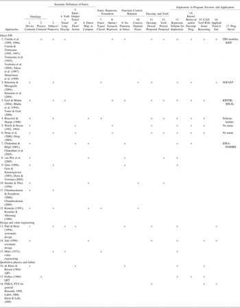
In this subsection the reviewed literature is recapped in Table 1. The 16 criteria used in the table are considered to delineate the differences and commonalities between the reviewed approaches. These criteria are classified under six items. Among those the item ontology delineates if the approach follows a device-centered or a process-centered perspective. Semantic definition of function identifies how the term function is defined. The criteria under this item are not mutually exclusive. As it is seen, there are various approaches that define function(s) as a subjective category as well as an input–output transformation performed by a component (Goel, Reference Goel1991; Goel & Chandrasekaran, 1992; Deng et al., Reference Deng, Britton and Tor2000), or in verb + noun form (Miles, Reference Miles1972; Umeda & Tomiyama, Reference Umeda and Tomiyama1997), or even as a direct mapping to components (Snooke & Price, Reference Snooke and Price1998; Chakrabarti & Bligh, Reference Chakrabarti and Bligh2001). Function representation formalism refers to the mode of function representation. Although some approaches cluster functions under different types, some approaches make use of syntactic representations. As an example to the former case, Keneuke (1991) was mentioned to define four function types. In the case of syntactic representation the representations of the function are more operational, either delineating the attributes, entities, phenomena, domain, and so forth (Welch & Dixon, Reference Welch and Dixon1994; Umeda & Tomiyama, Reference Umeda and Tomiyama1995), or the input–output variables (Deng et al., Reference Deng, Britton and Tor2000) associated with the function. The item of function–context relation identifies if the semantics of function is derived from the context or it is defined following the no function in structure principle. In the latter case, the definition of function allows modular operations, namely, making use of the subfunctions in different contexts exactly as they are defined and represented. The criteria under the last two items delineate the extent of applications of the methodologies as presented in the respective papers. Under the item of decomposition and verification it is mentioned if the authors propose methodologies for functional decomposition and verification of the functional design. The item of implementation in a programming environment and application checks if a representation scheme for computer programming is proposed, if a program is developed for functional decomposition and knowledge retrieval purposes, if the approach is integrated with some reasoning under a CAD tool, and if any industrial application of the methodologies/programs introduced in the paper exists, in addition to mentioning the names of the computer programs developed by application of the approaches.
A comparative view of the reviewed approaches

The demarcations in Table 1 should not be considered as a grading of the different FM approaches. Instead it indicates which trends are followed in FM and which approaches have been put in application up to this time. The plus signs in the table indicate that the feature represented by the relevant column is shared by the approach represented by the relevant row. The approaches are represented by referencing to a few pioneering papers of the author(s). Many of the places are left empty, either because the approach does not share the feature or there is no indication in the relevant papers that it shares. Among the indicated approaches the first group is the most relevant to the content of this paper because they directly aim at FM of complex systems. In the second group of references FM is not the prime objective but considered as a tool for the major concern of design or value engineering. In the third group are the references that develop either a qualitative physics theory potentially applicable for reasoning in FM applications or a framework for failure analysis in which FM can effectively be used.
The criteria for ontology development indicate that most of the approaches related to FM follow the device-centered ontology, which is pioneered by de Kleer and Brown (Reference De Kleer and Brown1984). In the case of Kitamura et al. (Reference Kitamura, Kashiwase, Fuse and Mizoguchi2004) and Kitamura and Mizoguchi (Reference Kitamura and Mizoguchi2004), it is explicitly stated that the developed functional ontology is based on device-centered ontology. This is implicitly the case with the others that are indicated to follow the device-centered ontology. It is only the approach of Umeda and Tomiyama (Reference Umeda and Tomiyama1995) that adapt the process-centered ontology proposed by Forbus (Reference Forbus1984). Regarding to the semantic definition of function, many of the approaches share the idea that function is a subjective category. However, as the frequency of the signs in the fifth and sixth columns indicate, this does not preclude defining the functions as a transformation between input and output values or as a relation to establish a direct mapping between the functions and components. These two seem to overwhelm the linguistically formed verb + noun approach especially among the papers directly related to FM. Among the design and failure analysis approaches the distribution seems to be equal, with less emphasis on the subjective character of function. Regarding the formal representation of function, the position of the approaches that have developed application programs are clearer than the others. Among those the representations in the form of function types and in a syntactic formalism are more or less in the same amount. Most of the approaches share the no function in structure principle. This does not mean that their approach obeys the principle in all extent, but it means that the principle is considered to be something worth achieving by the authors. Of course, there are approaches even among the ones that are implemented in programming environments that share the idea of context dependent functional definitions.
Decomposition and verification procedures are proposed together by most of the FM approaches that are implemented. Decomposition methodologies are proposed also by the purely design oriented classical theories of Pahl and Beitz (Reference Pahl and Beitz1988) and Suh (Reference Suh1990). It is common that the FM approaches propose representational schemes intended for computer implementation; however, until now a limited number of them have found implementation in computer environment. Moreover, only two of the approaches have been tried in the industrial environment. This indicates that the engagements with direct FM still remain in the research and experimentation phases. The design oriented approaches of Pahl and Beitz (Reference Pahl and Beitz1988) and Suh (Reference Suh1990), the qualitative physics theories developed by de Kleer and Brown (Reference De Kleer and Brown1984) and Forbus (Reference Forbus1984), and the failure oriented approaches have found application either in programming environments or in the industry.
3. RELATION OF FM WITH DIFFERENT RESEARCH FIELDS
One of the aims of FM is to make use of computers for reasoning in the level of modeling with functions. Reasoning with computers is most of the time implementation of AI techniques. Therefore, the relation between the AI research and FM is important for developing computer programs for FM. The research of design is, in fact, the major field from which the discussion of FM emerges. To make use of functions in the conceptual design phase and to develop tools to support design are crucially important. Finally, FM plays an important role throughout the life cycle of products. Maintenance, diagnosis, failure detection, failure recognition, and generation of solutions can be performed effectively in the realm of FM. Compared to the structural and behavioral analysis used for the same purposes FM analysis is expected to give results in the conceptual design phase. This section discusses the relation of FM with AI, design theory, and maintenance. In the discussion of each subsection, the relations of some classical approaches with FM are reviewed, and the directions of improvement by incorporating FM are mentioned.
3.1. AI and FM
Functional models of products/devices provide a high-level representational framework in which activities such as design, diagnosis, verification, and modification can be performed without reference to the actual structure of the system. Not only the FM itself but also the tasks performed on the model rely on human reasoning and recognition. Because AI techniques are aimed at modeling and assisting intelligent human activity and at reasoning, planning, diagnosis, and qualitative simulation, they can be utilized in product development-related activities, such as design and maintenance, with FM. This section provides a discussion of the application of AI techniques with FM.
Function reasoning (FR) is a research field that relates AI technology to FM (Chandrasekaran Reference Chandrasekaran1994a, Reference Chandrasekaran1994b). An FR scheme is composed of three elements (Far & Elamy, Reference Far and Elamy2005). “Ontology” describes the domain and the entities. “Representation scheme” models the entities and the relations between them. Finally, “reasoning” infers and explains how the entities function. An FR-based system can be used for planning and design purposes (verification, design), conceptualization purposes (representation, clustering), or explanation purposes (fault diagnosis and failure modes). FR adds functional concepts into MBR technologies (Umeda & Tomiyama, Reference Umeda and Tomiyama1997).
Specific AI techniques such as heuristic search (search for relevant functions), exploration and exploitation (designing higher level functions from sublevel ones and making use of the ones in the knowledge bases), pattern matching (comparing functionalities of different structures), clustering (composing classes of similar functions) have already been used for FR purposes. Far and Elamy (Reference Far and Elamy2005) consider such applications as the first generation FR systems and regards them as being restricted to direct list-matching inferences. There exist multiple correspondences between functional descriptions and behavioral descriptions, and between behavioral descriptions and a physical structure. In other words, function–behavior, behavior–structure couples are many-to-many mappings. However, it is a matter of reasoning to identify the most application relevant choices of functions, behaviors, and structures. Combining FM with MBR is useful to develop reasoning mechanisms for these purposes. Far and Elamy (Reference Far and Elamy2005) regard the combination of FM with MBR as the second-generation FR systems developed as an extension of the MBR technologies. In those the functional descriptions are related to a physical model of the system, namely, to the causal behavior relations in the system. FM equipped with MBR can be used for system simulations that involve the functionalities of diagnostics and failure analysis.
Far and Elamy (Reference Far and Elamy2005) mention four domain-independent tasks to which FR can be applied. Identification determines the functions associated with a given structure. Explanation gives answer to why a component is necessary to realize the intended purpose. Selection is used to determine and combine the components to perform the behavior necessary to realize the intended functions. Finally, verification is performed to test the functionality of the given structure under certain environmental constraints. The type of AI techniques applicable to these tasks can be mentioned as follows: direct matching (or mapping) of functional knowledge to physical structure and physical phenomena (e.g., catalog search in Parh & Beitz, Reference Pahl and Beitz1988), application of qualitative simulation of device and/or process models (de Kleer & Brown, Reference De Kleer and Brown1984; Forbus, Reference Forbus1984), and reasoning (verification and identification) about the relation between FRs and the physical phenomena (features) with qualitative physics (FBS model of 1990, 1995a, 1996, 2005; Umeda & Tomiyama, Reference Umeda and Tomiyama1995, Reference Umeda and Tomiyama1997).
Performance of functional modeling with AI-based techniques depends on the modeling approach. Modeling is affected by the representation of functions and their relations to the concepts employed in the modeling scheme (behavior, structure, etc.). The definition of function in the model is crucially important regarding applicability of AI techniques. The precision of the representation in the functional model defines a limit on the applicability of AI techniques that make use of those (Chandrasekaran, Reference Chandrasekaran2005). For instance, limiting the definition of function to a transformation between input and output variables results in difficulty in representing a function that does not transfer anything (Pahl & Beitz, Reference Pahl and Beitz1988; Welch & Dixon, Reference Welch and Dixon1994). Similarly, the representation of functions as limited numbers of discrete types cannot cover all possible functionalities. For example, it is not trivial how to represent a ToPrevent-type function of Keuneke (Reference Keuneke1991) with the three types, data function, energy function, and mass transfer function, in Schemebuilder (Bracewell & Sharpe, Reference Bracewell and Sharpe1996), or vice versa. With such definition of functions the search space of the AI techniques employed are restricted to a very narrow domain. Limiting the search space creates a major difficulty for application of AI techniques.
The FM approaches that adopt direct mapping of functions to components compose another case limiting the utilization of AI techniques. In such cases, the composition/decomposition of functions is solely managed by designers. Those methods conventionally describe the mappings in a matrix form (Suh, Reference Suh1990; Van Wie et al., Reference Van Wie, Bryant, Bohm, Mcadams and Stone2005). The application of AI techniques in these cases is limited to the search of matching functions to components, or to some matrix-based operations of multiple mappings. The difference between these direct mapping approaches and MBR-based approaches is as follows: the direct mapping approaches treat the compositional relation of functions and structures as explicitly given information. In contrast, MBR-based approaches reason out implicit causal relations. KRITIK is an analogy-based design support tool using case-based reasoning and MBR (Goel & Chandrasekaran, Reference Goel and Chandrasekaran1989, Reference Goel, Chandrasekharan, Tong and Sriram1992; Goel, Reference Goel1991; Bhatta et al., Reference Bhatta, Goel and Prabhakar1994; Yaner & Goel, Reference Yaner, Goel and Gero2006).
Application of AI techniques with FM is also important from product life cycle point of view. For instance, upgradeability is an important emergent concept currently inherited to the design paradigms for developing environment-friendly products. Partial functions of the products are upgraded or downgraded in either parametric or structural level. In this way the functionally different products, developed on the same original structure, share common modules or components over generations in time. For a FM scheme to support the design of upgradable products, the function representation should deal with multiple function models. Umeda et al. (Reference Umeda, Kondoh, Shimomura and Tomiyama2005) develop a design methodology of upgradeable products using FBS modeling. Association of different functions from the point of view of upgradeability, and building a structure that allows modular integration/disintegration and functional differentiation in time necessitate prediction and optimal design facilities during product development. These problems can effectively be formalized in an FM framework and addressed by application of AI techniques.
3.2. Design theory, product development, and FM
What FM provides for the design process is basically a model based on the functionalities and subfunctionalities within the system. Making use of such a model in the conceptual design phase is significant for managing the increasing complexity of the design processes. This is acknowledged by America and van Wijgerden (Reference America and van Wijgerden2000), who make use of extensive requirements modeling in a real industrial application. Bonnema and van Houten (Reference Bonnema and van Houten2006) investigate the use of models in conceptual design. They observe that models are used by designers to handle large amounts of data, for communication purposes and for analyzing of the problems. Yoshioka et al. (Reference Yoshioka, Umeda, Takeda, Shimomura, Nomaguchi and Tomiyama2004) demonstrate that functional models provide a structure for the design process and ease the handling of large amounts of data. In the following subsection a discussion of the two classical design methodologies that are in relation to FM is given. Then two design methodologies that are explicitly FM oriented are reviewed. Finally, some emergent CAD tools are introduced. These are implementations of the FM paradigms of their developers with some reasoning processes.
3.2.1. Sytematic design of Pahl and Beitz and axiomatic design (AD) of Suh
The systematic design developed by Pahl and Beitz (Reference Pahl and Beitz1988) divides the design process in four phases. In the first phase product planning and clarification of the task are performed. In this phase methods like market analysis, brainstorming, literature search, examination of existing solutions, and preparation of requirements lists are utilized. These activities can be regarded as taking place in the subjective realm. In the second phase conceptual design is performed. The most important steps in this phase are abstraction and systematic-logical thinking to identify the essential problems, setup function structures, setup classification schemes, and search for working principles. In the conceptual design phase the step from the subjective realm to the objective realm is made. The third phase is the embodiment of design. Based on the requirements, the functional structure, solution concepts, and preliminary layouts of main function carriers are developed iteratively. After selection and evaluation of the layout of the main function carriers the layout for the auxiliary function carriers are developed and evaluated. This phase is finalized by creating a preliminary parts list and possibly production documents. Considering the FM framework, this phase corresponds to the transition from behaviors to the design object. The fourth and last phase is detailed design. Detailed analysis on a component level and preparation of mechanical component drawings take place in this phase.
Pahl and Beitz (Reference Pahl and Beitz1988) define function as the general input/output relationship of a system whose purpose is to perform a task. It represents a flow, possibly, of energy, materials, or signals. Functions are decomposed into subfunctions and usually have the verb + noun form. The decomposition is presented as a block diagram of subfunctions, and is referred to as the function–structure. The functions in the structure are related to each other with the logical operators of AND, OR, and NOT.
Many FM techniques (Pahl & Beitz, Reference Pahl and Beitz1988; Suh, Reference Suh1990; Umeda & Tomiyama, Reference Umeda and Tomiyama1995; Chandrasekaran & Josephson, Reference Chandrasekaran and Josephson2000) decompose functions into lower levels of subfunctions. The resulting function–structure assists the designer with providing an overview of the system. Pahl and Beitz (Reference Pahl and Beitz1988) do not use the function representation for automated reasoning purposes. Many of the FM developers propose to do so (Umeda et al., Reference Umeda, Takeda, Tomiyama and Gero1990, Reference Umeda, Ishii, Yoshioka, Shimomura and Tomiyama1996; Umeda & Tomiyama, Reference Umeda and Tomiyama1995, Reference Umeda and Tomiyama1997; Chandrasakaran & Josephson, 2000; Kitamura & Mizoguchi, Reference Kitamura and Mizoguchi2004; Yoshioka et al., Reference Yoshioka, Umeda, Takeda, Shimomura, Nomaguchi and Tomiyama2004; Chandrasakaran, 2005), and among those, Umeda and Tomiyama implement an automated reasoning system with FM by making use of the QPT (Forbus, Reference Forbus1984). The systematic design of Pahl and Beitz (Reference Pahl and Beitz1988) does not provide a CAD tool to support design.
The AD developed by Suh (Reference Suh1990) is aimed toward a quick and systematic development of complex systems. It proposes a method to structure and organize the design process. AD starts with considering high-level FRs. The goal is to satisfy the FRs independent of one another. The high-level FRs are embodied by high-level design parameters (DPs). Then, the high-level FRs are decomposed into lower level FRs, which should be satisfied by DPs. This zigzag process continues until the FRs can no longer be decomposed. Within this method, design is considered to be the mapping process between the FRs in the functional domain and the DPs in the physical domain. The result of this process is a functional decomposition of the design and a decomposed physical embodiment.
The main ideas behind the AD are summarized by Suh (Reference Suh1990) with two axioms. The first axiom, called “the independent axiom,” forces to maintain the independence of FRs. During the design process, the designer goes from the FRs in the functional domain to DPs in the physical domain. The mapping between these two must be such that a perturbation in a particular DP should not affect any other functional requirement than its referent. Within a matrix representation of FRs and DPs, such an “uncoupled design” corresponds to a diagonal matrix, whereas a “coupled design” to a triangular matrix. The second axiom, called “the information axiom,” enforces to minimize the information content. It states, among all the designs satisfying the first axiom, the one with minimum information content is the best. In other words, the best design is a functionally uncoupled design that has the minimum information content. However, considering many complex systems, it is not always possible to decouple the FRs. Suh (Reference Suh1990) states that decoupled FRs are desirable, but there are no developed means or tools to achieve this. This issue remains as a research topic where FM can effectively be used. In contrast to many FM techniques (Umeda & Tomiyama, Reference Umeda and Tomiyama1995; Chandrasekaran & Josephson, Reference Chandrasekaran and Josephson2000) AD does not make a separation of objective and subjective realm in design.
3.2.2. FBStr model of Gero and FBS model of Umeda and Tomiyama
The FBS model of Umeda and Tomiyama (Umeda et al., Reference Umeda, Takeda, Tomiyama and Gero1990, Reference Umeda, Tomiyama and Yoshikawa1995a, Reference Umeda, Ishii, Yoshioka, Shimomura and Tomiyama1996, Reference Umeda, Kondoh, Shimomura and Tomiyama2005; Umeda & Tomiyama, Reference Umeda and Tomiyama1995, Reference Umeda and Tomiyama1997; Yoshioka et al., Reference Yoshioka, Nomaguchi and Tomiyama2001; Cagan et al., Reference Cagan, Campbell, Finger and Tomiyama2005) and the dynamic design model proposed by Gero (Reference Gero1990) present design processes that are more FM oriented. Gero (Reference Gero1990) defines the design activity “as a goal-oriented, constrained, decision-making, exploration, and learning activity that operates within a context that depends on the designer's perception of the context.” He points to two research issues for design: “representation frameworks,” and “transformation processes.” He develops a representational frame with using the concepts of function, behavior, and structure, and then explains the steps of transformations between these. The design procedure, which is a gathering of these steps, is an iterated comparison of the structural behaviors and expected behaviors (associated with the intended functions) and updating the structure to match these two. The following steps are delineated as activities in design: formulation, synthesis, analysis, evaluation, reformulation, and production of design description. Gero and Kannengiesser (Reference Gero and Kannengiesser2004) consider design as a dynamic process in which the view of the designer changes in time depending on the outcome. The change of the external world and the internal world of the designer determine the dynamic “situatedness” throughout the process. Whereas Gero and colleagues describe their design methodology within the framework of their FBStr model, they do not propose a formalized systematic to decompose the functions or to associate the functions with behaviors and structure. Although their FBStr scheme is useful to demonstrate the conceptual relation between function, behavior, and structure, the FBS model of Umeda and Tomiyama (Umeda et al., Reference Umeda, Takeda, Tomiyama and Gero1990, Reference Umeda, Tomiyama and Yoshikawa1995a, Reference Umeda, Ishii, Yoshioka, Shimomura and Tomiyama1996, Reference Umeda, Kondoh, Shimomura and Tomiyama2005; Umeda & Tomiyama, Reference Umeda and Tomiyama1995, Reference Umeda and Tomiyama1997) provides a systematic method for decomposition and embodiment of functional design.
Umeda and Tomiyama (Reference Umeda and Tomiyama1995) mention that although the manipulation of the behavioral structure is possible by making use of qualitative physics, the mental simulation of functions is still difficult to be done by computers. The FBS modeling is proposed as a new knowledge representation scheme to systematize functional decomposition in the subjective realm and then to develop a CAD system that helps the embodiment of the designed functions into a behavioral and structural system in the objective realm (Umeda et al., Reference Umeda, Takeda, Tomiyama and Gero1990, Reference Umeda, Tomiyama and Yoshikawa1995a, Reference Umeda, Ishii, Yoshioka, Shimomura and Tomiyama1996, Reference Umeda, Kondoh, Shimomura and Tomiyama2005; Tomiyama et al., Reference Tomiyama, Umeda and Yoshikawa1993; Umeda & Tomiyama, Reference Umeda and Tomiyama1995, Reference Umeda and Tomiyama1997; Yoshioka et al., Reference Yoshioka, Nomaguchi and Tomiyama2001, Reference Yoshioka, Umeda, Takeda, Shimomura, Nomaguchi and Tomiyama2004; Cagan et al., Reference Cagan, Campbell, Finger and Tomiyama2005). The authors delineate two phases of the design process. In the first phase, the user specifies the required functions and decomposes them independent of any physical behavior or system structure. The designer is aided by the decomposition knowledge of function prototypes in this phase. In the second phase, the designer enters the objective realm by embodying the functions into behaviors and structural models. The functional decomposition comes to an end when the function–behavior relations are related with some physical features. The designer chooses physical features that can embody each subfunction. A physical feature consists of physical phenomena, entities, and relations among entities. The FBS model assumes knowledge bases for function prototypes, physical features, and physical phenomena. After instantiating physical features, the designer might discover that some features cannot be realized. As will be explained in the next section, the FBS modeler assists the designer to overcome such situations. Furthermore, the authors propose the understanding of function redundant design, which aims at realizing functions with other means than the ones in the initial design (Tomiyama et al., Reference Tomiyama, Umeda and Yoshikawa1993; Umeda & Tomiyama, Reference Umeda and Tomiyama1995; Umeda et al., Reference Umeda, Ishii, Yoshioka, Shimomura and Tomiyama1996). The authors give the definition of a redundant function as follows: “A redundant function is a function that can be realized by other physical features than the feature that realizes the function in its normal state” (Umeda & Tomiyama, Reference Umeda and Tomiyama1995). This means that the physical structure does more than what is needed to realize the function. They apply such a design to maintain the operation of the system in case some functions are not realized regularly.
Umeda and Tomiyama (1997) propose the understanding of “innovative design” (a term also used by Gero, 1990Footnote 2; Bhatta et al. Reference Bhatta, Goel and Prabhakar1994) against the conventional understanding of conceptual design methodology. The conventional conceptual design methodology is based on configuration design, and makes use of a catalog in which functions are associated with some elements/components. Innovative design, contrarily, does not only make use of such a catalog, but also aims to propose new functionalities by new compositions and new usages of components in response to the dynamically arising needs. In other words, the innovative design does not follow only the top-down design path, from function to structure, but also the bottom-up design path, from structure to function. In this way the innovative design is performed in an interactive way between the designer and the structure designed. Throughout this interaction the intermediate level functions between the global intentions and structure evolve with the structure itself. In Shimomura et al. (Reference Shimomura, Yoshioko, Takeda, Umeda and Tomiyama1998), the authors explicitly mention “discovery of functions” as an operation of a functional evolution process. The idea of top-down–bottom-up design aims to achieve theory and phenomena at the same time throughout the design process. Accordingly, Kitamura and Mizoguchi (Reference Kitamura and Mizoguchi2004) mention that function decomposition should not be performed only in the functional domain but by going back and forth between functional, behavioral, and structural domains.
3.2.3. Emergent CAD tools making use of FM
Developing CAD tools for design purposes is one of the important aims of FM researchers. As Table 1 indicates, there have been FM approaches that are already implemented in computer programming environments and developed into CAD programs. What is meant with a CAD program here is a computerized design environment in which modeling, data base storage, and retrieval facilities, and most importantly, reasoning algorithms are utilized to support the human designer. All the CAD programs indicated in Table 1 are in their research and development phases, but they share the potentiality to be applied in industry in the near future. In the following we introduce the FBS modeler and knowledge intensive engineering framework (KIEF) of Umeda, Tomiyama, and colleagues (Tomiyama et al., Reference Tomiyama, Umeda and Yoshikawa1993; Yoshioka et al., Reference Yoshioka, Umeda, Takeda, Shimomura, Nomaguchi and Tomiyama2004); KRITIK and IDeAL of Goel and Bhatta (Reference Goel and Bhatta2004); IDEA-INSPIRE of Chakrabarti et al. (2005); and function embodiment structure-extended recursively (FEST-ER) and Schemebuilder of Bracewell and Sharpe (Reference Bracewell and Sharpe1996).
The FBS modeler is a design support tool developed by implementing the FBS modeling introduced in the previous section. The modeler contains two types of knowledge. The physical features, namely, physical phenomena (process), entities, and spatial relationships of entities, correspond to the knowledge about the objective behavior of the system. The knowledge about the subjective functionalities is stored in two forms: as decomposition knowledge (how functions are decomposed into subfunctions) and behavioral knowledge (which physical feature realize the functions). In designing a product with the FBS modeler, the designer first defines and decomposes the required functions. Then physical features are instantiated to realize the functions.
If the realization of any of the instantiated physical features needs some state transitions that are not possible with the existent physical features, the situation is automatically detected by the modeler. The designer initiates the required physical features by selecting from the candidate solutions suggested by the modeler. Accordingly, the functions corresponding to the newly initiated physical features are automatically instantiated. Finally, the relations between the entities are defined based on the instantiated physical features (unification). A behavior simulation based on QPT can be used to envision the behavior of the product. The simulation identifies unrealized phenomena, side effects, and unrealized functions. The FBS modeler is equipped with a function redundancy designer, which generates candidates of function redundancy by searching for potentially similar functions in the model. The function redundancy designer has been successfully applied to a photocopy machine (Tomiyama & Umeda, 1993; Umeda et al., Reference Umeda, Ishii, Yoshioka, Shimomura and Tomiyama1996). The FBS modeler is also equipped with a control program generator, which generates a sequence of behaviors to satisfy the transition sequence of functions. The sequence control program first generates transition rules making use of qualitative reasoning and quantitative information for state transitions. Then it outputs a C code for the implementation of these rules (Tomiyama et al., Reference Tomiyama, Umeda and Yoshikawa1993).
KIEF is a physical ontology based support system to integrate multiple engineering models and to allow their flexible usage throughout the design process (Yoshioka et al., Reference Yoshioka, Umeda, Takeda, Shimomura, Nomaguchi and Tomiyama2004). The physical ontology that underlies KIEF is composed of the following five conceptual categories: “Entity,” denoting an atomic physical object; “relation” denoting the static structure between the entities; “attribute,” indicating the state of the entity; “physical phenomena,” designating physical laws and rules; and “physical law,” representing relations among attributes. Based on this ontology the designer uses KIEF to construct and develop a metamodel of the design. The metamodel mechanism is pluggable, in the sense it integrates and maintains the relationships and consistency among multiple models that represent a design object from different views or aspects. This feature enables the system to integrate the knowledge derived by using different domain theories, such as electronics, dynamics, and so forth. Explicit representation of the physical phenomena underlying all domain theories is therefore crucial in KIEF. In the design process with KIEF, the designer first builds an initial metamodel by selecting and combining physical features from the knowledge base of the system. In this stage, the FBS modeler and a qualitative process abduction system are utilized for functional decomposition and physical feature selection. Then, KIEF automatically reasons out the physical phenomena that can occur to the design object and detects the unintended ones, namely, the ones that were not foreseen by the designer. Next, the designer analyses the design object by evaluating it with different modelers. KIEF supports the exchange of data and maintenance of consistency in between the different modelers. Currently, seven design modeling systems are plugged to the KIEF system: a qualitative physics reasoning system, ProEngineer, which is a two-dimensional draw modeling system; the FBS modeler; the qualitative process abduction system; a catalog-retrieving system; and Mathematica-based engineering analysis systems.
The KRITIK system developed by Goel and colleagues (Goel & Chandrasekaran, Reference Goel and Chandrasekaran1989, Reference Goel, Chandrasekharan, Tong and Sriram1992; Goel, Reference Goel1991; Yaner & Goel, Reference Yaner, Goel and Gero2006) takes the specifications of desired functions as the input and produces the specifications of the structure that realizes those functions as the output. The specifications of the output correspond to the symbolic representation of the configuration of the components and the connections between them. The IDeAL program developed by Goel, Bhatta, and colleagues (Goel & Bhatta, Reference Goel and Bhatta2004; Bhatta et al., Reference Bhatta, Goel and Prabhakar1994) can be considered as the succeeding program of KRITIK. It is based on the SBF ontology (mentioned before); generic teleological mechanisms (GTMs) to represent the causal design patterns in behavior–function models making use of the concepts of the SBF ontology; and a model-based analogy (MBA) to reason about the similarity, transfer, and learning of GTM patterns. The MBA reasoning takes the specifications of a target design in the form of FRs and structural constraints and outputs both an SBF model and a structure as the solution. For doing this, the MBA makes use of the database of existing GTMs, which correspond to the already stored or learned design patterns. The GTM patterns correspond to designs of pieces of structures that perform some function. A function corresponds to producing some particular output behaviors when input with particular behaviors. The SBF representation, which is in the form of function–behavior–function … F → B → F → …→ F(s), hierarchy, breaks down the behaviors into smaller ones easier to search, transfer, and manipulate. IDeAL retrieves the pieces of designs in database by comparing their patterns of functions (input–output behaviors) with those of the desired design. If any stored design piece is found to match to some degree to the desired one, IDeAL modifies it to deliver exactly the desired function. It first tries to identify and modify a component. If it fails, it attempts to modify the device topology using the knowledge of GTMs it has in the database. For the latter purpose, IDeAL uses the identified difference between the desired and candidate designs in terms of input output states (behaviors) of functions. If any existing design piece (mechanism) reduces the same difference as identified, that mechanism is retrieved. The program tries to integrate the retrieved mechanism to the candidate design to make it identical with the desired. Another advantage of IDeAL is that it can learn the required GTM pattern once it is provided with a sample solution by an oracle in order to fulfill a desired design. It identifies the GTM pattern it needs by differential diagnosis of the candidate solution it composes and the solution provided by the oracle. Model-based learning and analogical reasoning are central to all these reasoning activities that take place within IDeAL. Finally, IDeAL evaluates the candidate designs by a qualitative simulation of the generated model.
Chakrabarti proposes a functional representation to support idea generation for product design using the analogy between the knowledge of natural and artificial systems (Chakrabarti et al., Reference Chakrabarti, Sarkar, Leelavathamma and Nataraju2005). The SAPPhIRE model consists of seven concepts to represent function, behavior, and structure of instances. The model is implemented as a software program called IDEA-INSPIRE. The program supports the designer with an automated analogical search. Initially, the designer represents a function with a set of verb, noun, and adjective (called behavioral language). Then the program performs an analogical search in the hierarchical network of those seven concepts to find the motions and realization structure in the both domains. Although the system helps the designer to generate new ideas, design evaluation has to be manually performed.
The Schemebuilder program developed by Bracewell and Sharpe (Reference Bracewell and Sharpe1996) is based on the bond graph ontology and the information structure of FEST-ER. Schemebuilder is a knowledge-based design environment that generates alternative schemes of solutions in the form of a function–means tree structure by making use of some decomposition principles, which are mentioned in Section 2.5. During this decomposition the required functions must be present in the hierarchy classified functional embodiment knowledge base of Schemebuilder. The decomposition and embodiment process develops an instance of FEST-ER, which is an acyclic directed graph-based information structure (a tree structure of functions). FEST-ER supports referencing to already embodied functions, in case they appear more than once, and embodiment of more than one functions by single means. All possible alternative schemes are created by using an assumption-based truth maintenance system. The designer is free to extend the alternatives until the embodiment phase or to choose any of them and stop proceeding with the others in any stage. Schemebuilder provides also a simulation engine that can be used for verification.
3.3. Maintenance and FM
AI techniques such as expert systems and MBR are commonly used for fault diagnosis purposes. Expert systems make use of the subjective information of humans. However, it is not always easy to access to expert knowledge and to translate it into computer language. Moreover, expert systems are not adaptable to changes. A model-based diagnostic system uses a model of the system (product, service, software, etc.) to reason about its behavior. It simulates the model, finds out what the system is supposed to do, and compares this with what the actual system does. Model-based diagnostic systems are more robust in comparison to the ones making use of expert systems.
The most common methods dealing with maintenance are driven by failure analysis. These include, besides expert systems and model-based diagnostic systems, reliability-centered maintenance (RCM), FMEA, failure mode and effect and criticality analysis, functional failure analysis (FFA), FTA, and total productive maintenance. Usually the common aim of these methods is to reduce the cost, either by increasing the reliability of the system and/or by improving and optimizing maintenance strategies. Definitions and some applications of these methods can be found in Rausand (Reference Rausand1998), Labib (Reference Labib2006), and Klein and Lalli (Reference Klein and Lalli1989). Description and categorization of functions are used in methods such as FFA. Techniques such as FTA or functional block diagrams can be used to track causes and consequences of faults in a system. These techniques are often used in RCM and model-based diagnostic systems.
Umeda and Tomiyama (Reference Umeda and Tomiyama1995) state that a component of a system can be used in other ways than the ones intended by the designer. For instance, in a failure situation, another component, rather than the faulty one, can perform the function, perhaps in a less efficient way. As mentioned in Section 3.2.2, the authors name such a situation as functional redundancy. Conventional redundancy methods aim to increase reliability by adding redundant components to the system. These differ from the functional redundancy proposed by Umeda and Tomiyama (Reference Umeda and Tomiyama1995). In the latter, redundancy does not refer to a physical component but to the capability of performing a function. Redundant functions are intended to be found among the components of the system, without addition of new parts. FM and qualitative physics are potential tools to develop a framework in which functional redundancies can be systematically generated. A fault diagnostic system based on FM can make use of the functional redundancies to find out repair methods to deal with the encountered faults.
4. APPLICATIONS OF FM IN ONGOING RESEARCH
In this section an introduction of the ongoing research in the Intelligent Mechanical Systems Group is given. The work reported is inspired by and makes use of the ideas developed within the FM framework. The basic issues of the projects, such as evolvability, unpredicted interferences, intelligent maintenance, and service modeling, are explained in the context of the FM.
4.1. Evolvability
There are usually considerable differences between the functional description of contemporary systems and those of their first releases in the past. With ever-growing functional changes, the complexity of the systems tends to increase, sometimes to unmanageable degrees. How we deal with increasing complexity attributable to system modifications in time is not trivial. To have good control of complexity it is necessary to have a good system overview. However, the large amount of data and large teams of design engineers from diverse disciplines make it difficult to construct this overview.
A system overview is important to understand the relation between subsystems and to judge the information stream in the process. Overlooking the relations between diverse disciplines often results in unexpected problems in the design. Regarding the interaction of different disciplines, one can argue that the vertical traceability and horizontal traceability are both important (Fig. 1). Horizontal traceability is in direct relation to managing the dependencies between separate disciplines.
A system is called evolvable if its complexity does not increase in unmanageable amounts when new functionalities are introduced. To achieve evolvability, the new or modified behaviors introduced to the system should minimally disturb the functions inherited from the previous architecture.
Evolution of a system corresponds to equipping it with new functionalities by introducing new behaviors. The handling of this activity can be termed as change management. Introducing new behaviors corresponds to adding new components to the system architecture. Any modification in the architecture results in an effect on the existing parts of the system. In fact, it is the undesired interactions between these components that result in the increase in complexity. The questions, “how the different parts are affected,” “how these effects can be minimized,” and “how to organize the design, at the very beginning, in order to minimize the number of interactions” are crucial from change management point of view. An overall system view based on FM constructs a framework within which such questions can be answered. Another issue regarding evolvability is interface management, which can be described as managing all sorts of connections between different parts of the system. Interface management is particularly important for complex systems in which some of the modules can temporarily be replaced to modify the functionality of the overall system.
One of the researches going on in the Intelligent Mechanical Systems Group is about developing an automated robotic system for disassembly tasks. To achieve this, a robot arm must be able to perform various tasks, such as pushing/pulling big masses, lifting/cutting single pieces, carrying/placing parts to be recycled, extracting/storing delicate usable parts, and perhaps some more that cannot be anticipated in the design phase. Considering that all these will be performed by a single robot arm, the design should support the change of the robot hand at the tip of the arm. The mechanical, power and sensory interface of the arm with the hands and control of different hands with the same platform are two challenging tasks in this research. What is aimed at is to prepare a common mechanical–power–communication frame to which all different hands can be attached in the same way. The design of the attachment frame in the robot arm and the generic frame for the various hands is an issue. A common control frame should be able to control all kinds of hands. For example, a few generic commands such as act, stop, redirect, release_hand, attach_hand should be enough to utilize different hands for pushing, pulling, holding, cutting, screwing, and placing purposes. The ongoing research aims at preparing the interfaces to support the various robot hand modules, and to be prepared to adapt to the new ones that will potentially appear in future.
4.2. Detection of unpredicted interference problems
This section introduces the ideas to develop a method to deal with unpredicted problems as the consequences of destructive couplings of engineering domains. Tomiyama and D'Amelio (Reference Tomiyama, D'Amelio and Krause2007a, Reference Tomiyama and D'Amelio2007b), D'Amelio and Tomiyama (Reference D'Amelio and Tomiyama2007), and Tomiyama et al. (Reference Tomiyama, D'Amelio, Urbanic and ElMaraghy2007) present the background research in relation to these ideas. The system to detect the unpredicted interference problems is called a design interferences detector (DID). DID enables one to envision the destructive couplings in advance, in the early phases of conceptual design. Destructive couplings correspond to the undesired and unpredicted interactions that result in undesired and unpredicted behaviors. A MBR and an extension of FBS model (Umeda & Tomiyama, Reference Umeda and Tomiyama1995) constitute the foundations of the methodology for the DID.
There are already some techniques intended to deal with complexities. The approach based on the design structure matrix (Browing, Reference Browing2001) and the methodology of AD (Suh, Reference Suh1990) can be cited in this regard. Suh (Reference Suh1990) suggests a method for the elimination of the “spaghetti” code by identification of a logical structure. His aforementioned independence axiom aims to maintain the independence of FRs. These two methods are based on the analysis of well-formulated interactions of which the designer is already aware. They are not aimed at dealing with unpredicted interactions among subsystems. In contrast, the DID method aims at developing an automated analysis tool that finds out unpredicted interactions that are not trivially recognized within the design paradigm.
The DID is composed of a conceptual design model described by the engineer, a qualitative reasoning system (QRS) to detect all possible behaviors, and a filter to distinguish unpredicted problems (Fig. 5). The designer describes conceptual description of the system with the behaviors that are required. The DID reasons out all possible physical behaviors that can occur by making use of QPT (Kuipers, Reference Kuipers1994). The generated behaviors include both intended and unintended behaviors (Fig. 3). The unintended behaviors are filtered out by separating intended behaviors from all possible behaviors. Unintended behaviors are the source of unexpected functions realized by the system and recognized by the user. Once the unintended behaviors are filtered out the designer can reason out the unpredicted problems as the potential problems for future.
The design interferences detector process.

The FBS model provides both a methodology to structure knowledge and a framework for the application of qualitative reasoning to perform verification and identification of FRs. In FBS, the relation between a behavior and state is based on the physical principles applicable to the system. Once all entities and relations among them are defined in the FBS framework, the QRS reasons out physical behaviors based on the QPT. DID is an extension of FBS, obtained by incorporation of the QRS module. The original FBS, which does not contain the QRS module as proposed here, does not deal with physical phenomena explicitly; therefore, it cannot reason out unpredicted functions. A behavior can lead to new states that in turn initiate new behaviors. The mutual dependency between behaviors and states (hence, structure) are governed by physical phenomena, but they cannot be directly reasoned out without a QRS making use of fundamental physical principles.
Figure 6 illustrates the general model of the proposed DID tool, called function–behavior–physical phenomenon–state model (FBPhPhS). FBPhPhS integrates FBS and QRS by explicitly including the physical phenomena between behaviors and states. The concept of attributes of relations is included in the FBPhPhS model to prioritize the behaviors. The attribute of connected, belonging to relation, signifies the distance of the connection between entities. If two entities are not physically connected, the original FBS does not consider that there might be a coupling between the two. Such a situation happens when physical phenomena affect each other from a distance, as in the cases of electromagnetic field and heat transfer effects. The difference of FBPhPhS with the original FBS is illustrated in Figure 7. In the first figure the physical phenomenon acts on the two directly connected entities. In the second figure, the physical phenomenon acts on two disconnected entities and results in their state transition. However, it should be noted here that the described scheme also results that the QRS reasons out a huge number of unfeasible (superfluous) behaviors.
The function–behavior–physical phenomenon–state general model description.

Differences between function–behavior–state (Umeda & Tomiyama, Reference Umeda and Tomiyama1995, Reference Umeda and Tomiyama1997) and function–behavior–physical phenomenon–state model given by attributes of relations. [A color version of this figure can be viewed online at www.journals.cambridge.org]

4.3. Reliability, availability, maintainability, and safety
The objective of this research is to develop a design methodology to increase the availability for complex systems such as offshore wind farms (Van Bussel & Zaaijer, Reference Van Bussel and Zaaijer2001, Reference Van Bussel and Zaaijer2003). The aim is to develop an intelligent maintenance system capable of responding to faults by reconfiguring the system or subsystems, without increasing the service visits, complexity, or costs. The idea is to make use of the existing functional redundancies within the system and subsystems to maintain operation, even at a reduced capacity if necessary. The possible solutions can range from using the capabilities of the adjacent components or subsystems to setting up different operational modes. There are usually functional redundancies in the system provided by its components, which are overlooked because of the lack of information. Typically, each component in a system is selected by the designer to perform a specific task. However, most of the time the components can be used for purposes not specified in the particular design. This feature can be used to provide a required function in the case of a fault. Umeda et al. (Reference Umeda, Tomiyama, Yoshikawa, Kimura and Rolstadas1989, Reference Umeda, Tomiyama, Yoshikawa and Shimomura1994, Reference Umeda, Tomiyama and Yoshikawa1995b) and Echavarria et al. (Reference Echavarria, Tomiyama and van Bussel2007a, Reference Echavarria, Tomiyama and van Bussel2007b) present the background research for this project.
The intelligent maintenance methodology proposed here (Fig. 8) involves two main modules: one applied at the design stage and the other at the operational stage. At the design stage, the FBS model feeds the functional redundancy designer, which is responsible for providing the information on potential existing redundancies of the system. This is intended to support the component selection. At the operational stage, there is a fault diagnosis system composed of a qualitative physics simulator and a model-based reasoner. In this stage, two types of repair methods can be followed: control type and reconfiguration (functional redundancy type; Umeda & Tomiyama, Reference Umeda and Tomiyama1995). Control-type repair methods correspond to strategies that can be applied by a controller in a way of instant response (Shimomura et al., Reference Shimomura, Tanigawa, Umeda and Tomiyama1995). Reconfiguration corresponds to compensating the functionality of a failed component with the redundant functions of other components (Umeda et al. 1995). The proposed methodology here follows the idea of reconfiguration-type repair method.
Intelligent maintenance methodology. [A color version of this figure can be viewed online at www.journals.cambridge.org]

To understand the causes of the failures it is important to understand how the system works, and what the interactions between the domains are. In addition, tools such as a tree-fault diagram or FMEA are useful to identify connectivity and criticality of components, which are important for system reliability. This information points out to critical components for the designer to give special attention when locating functional redundancies within the system. As a first step this knowledge should be expressed in qualitative terms to facilitate the reasoning process. In the proposed methodology knowledge is represented using the FBS modeling. The system description within the FBS model provides the knowledge of connectivity between the components by a hierarchical network of functions. The model-based reasoner makes use of this structure to build the object model and make reasoning with qualitative physics.
4.4. Service modeling
Service engineering is an emerging discipline studying the design, production, and maintenance of services. Service engineering aims at establishing a methodology to improve the quality and productivity of service processes using the techniques developed in the field of engineering (Tomiyama et al., Reference Tomiyama, Shimomura and Watanabe2004). Service modeling is positioned as one of the essential research issues to connect services as design objects with engineering as a means.
FM contributes to the improvement of product design processes by providing guiding strategies to incorporate computational supports (Section 3.2.3). This facility is due to the fact that FM enables designers to efficiently use and organize the conceptual knowledge such as function, behavior, structure, and state. To apply the results of FM work to service modeling, the representation of services and related concepts should be clarified and formalized in an analogy and in comparison to those in FM. There are few studies conducted to develop methods and tools for service design (Arai & Shimomura, Reference Arai and Shimomura2004, Reference Arai and Shimomura2005). Arai and Shimomura (Reference Arai and Shimomura2004, Reference Arai and Shimomura2005) do not formally define the representation of service, and in their papers the relation between the service modeling and FM is not mentioned. Particularly, activities, which are the design objects of service, their values, which delineate the performance of the service, and the relations between activities and value, have not been explicitly defined as the relation between the function and structure in product design. In FM, functions are treated as specifications given or developed during the design process and structure is designed to satisfy the functions. In service modeling, value is the final goal to be attained or increased. The concept value is in relation with the question, What is the service for? A set of activities represent the design objects of the service domain. They answer the question, What is the service?
Currently, a theory of service modeling, borrowing the concepts of FM, and a service CAD tool are being developed in the Intelligent Mechanical Systems group. The representation of service is based on the formalization introduced by Tomiyama et al. (Reference Tomiyama, Shimomura and Watanabe2004): “Service is an activity (or a set of activities) that the service provider offers to the service receiver through service channels in a service environment and generates values for the service receivers.” In developing the service modeling theory, the following conceptions are borrowed from FM.
1. Development of primitives: Function primitives help designers describe and classify functions and the relations to other concepts in product design. One of objectives of researchers in FM is to develop function primitives varied in terms of the domain of applications (e.g., design of mechanics; Chandrasekaran, Reference Chandrasekaran2005). Similarly, services and the related concepts should be analyzed and classified to develop the primitives of service. For instance, “message type services” and “massage type services” provide different effects on service receivers (i.e., increase of the receiver's knowledge and state transition of the receiver's physical attribute; Tomiyama et al., Reference Tomiyama, Shimomura and Watanabe2004). The difference can be identified in terms of the primitives employed in a service model.
2. Composition knowledge: In analogy to hierarchical function decomposition, value and activity are decomposable elements in a service model. Hierarchical relations among values and causal relations among activities should be explicitly considered, or implicitly obtained by reasoning techniques.
3. Correspondence between objective realm and subjective realm: One of the main contributions of FM is the separation of the objective concepts (e.g., structures and their behaviors) from the subjective (e.g., functions and the relations to the corresponding behavior). A similar separation is necessary in service modeling so as to distinguish the objective descriptions of activities (e.g., manuals and activity flow charts) from the subjective perception of the values of the activities.
4. Description of specifications (requirements): It is often the case that functional knowledge is not well documented in practice. This situation is comparable to the lack of descriptions about value of the services in service modeling. Without the descriptions of values designers cannot explain or reason about a certain activity with reference to user needs. Therefore, development of an overall description framework is crucial also for service modeling.
4.5. The contributions of the ongoing research to FM
After mentioning how FM will be used in the ongoing research, here is given a discussion of how these researches will contribute to FM. The idea of evolvability does not only aim at designing changeable structures with flexible interfaces, but also developing a representation framework adaptive to the modifications in the structure. Such a framework should reveal the possibilities of change and modification of system functionalities. It should easily handle the change in the representational framework. In this way the evolvability research will contribute to FM by developing a dynamic representation model. The research on unpredicted interference problems necessitates representing not only the functionalities within the system but also the interactions that occur within the functionalities, modules, and components. Once the interactions of structural elements are made explicit by using the FM framework, their future effects can be predicted. The research will develop FM by introducing representational and reasoning tools to detect sources of future problems. The work on intelligent maintenance will extend the use of FM into life cycle aspects. The research will develop tools to detect and represent redundant functions. With this project the use of FM will be extended to out of the borders of the conceptual design. It will allow making use of the functional model of an existing system for maintenance purposes. Finally, service modeling develops a representation of service with an analogy to FM. The concepts developed for the service modeling will also influence the understanding of FM. The requirements of services are usually more than what a single product or subsystem can deliver. A function in a service can be fulfilled by the cooperation of various subservices, systems, and products. This requires defining functionalities that consider cooperated usage, rather than a mere aggregation, of subfunctions provided by subsystems, as well as human-centered activities. The service modeling project will also provide FM with the new types of functions corresponding to those human-centered (friendly attitude, effective talk) means of service.
5. CONCLUSIONS
In this work a review of FM approaches and applications is performed. The review of FM approaches intends to build up a general FM framework by bringing together and relating conceptions and ideas proposed by various FM researchers. The basics of the framework is the separation of the subjective and objective realms regarding to design objects and considering functions as subjective categories linking these two. The linking is achieved by the subjective recognition of some objective behaviors as functions. The review is based on a discussion of the fundamental notions and principles in FM: the concept of function and functional ontology, the intermediate nature of functions between needs and objects, function structure relation, no function in structure principle, and functional decomposition. Having a grasp of these discussions in the literature is considered to be crucial for building up a FM framework. The considerably more relevant approaches are compared in a tabular form based on criteria reflecting these notions. This tabular comparison is believed to reveal the mainline trends of handling these issues.
There are various approaches to FM, not all of them compatible with each other. The variety seems to be a result of the different disciplines in which the FM engineers are educated as well as the different application domains the particular FM are aimed at. This situation brings up the question if there is any FM representation that is applicable to all domains or that can cover all possible modeling schemes. The KIEF program (Yoshioka et al., Reference Yoshioka, Umeda, Takeda, Shimomura, Nomaguchi and Tomiyama2004) should be considered to achieve this partially as it integrates different modeling schemes by representing the physical phenomena underlying all, and as it does not construct an explicit functional model that covers all. Seemingly the FM research is on the level of integrating/relating different modeling schemes by preserving their own existence, but not yet on a level to develop an encompassing FM paradigm.
The relation of FM with the research fields of AI, design theory, and maintenance are considered. This is because these are the research fields through which FM can jump over the borders of research and be put in application for practical purposes, such as design, diagnosis, and maintenance. In the discussion basic classical approaches and theories are reviewed mentioning their relation with FM and the promises of FM to advance those. Some FM approaches that are developed into concrete CAD tools are detailed to emphasize the contributions of FM and function-based reasoning, particularly to the design process.
Finally, the basic ideas underlying the research activities in the Intelligent Mechanical Systems Group are introduced. These ideas have emanated as a result of approaching to different systems and problems with the FM perspective. Evolvability of systems, detection of unpredicted interference problems, intelligent maintenance making use of redundant functions, and service modeling are possible to be formalized as concrete research issues either within the functional modeling framework or by establishing an analogy with its concepts. The ongoing research activities mentioned here should be regarded as the future work that will evolve on this paper.
This paper reveals that there are two fundamental advantages that FM provides for engineering. The first one is an overview of the whole system with terms (functions), which are easy to comprehend. By making use of such an overview the link between the higher and lower levels of system description is achieved. In addition, the interactions of different engineering domains in the lower levels are clarified. These are crucial for design, improvement, and maintenance purposes. The second facility provided by FM is that it constructs a framework in which computer reasoning can be performed. As the examples in Section 3.2.3 reveal, functional decomposition, verification, qualitative simulation of behaviors, delineation of the unexpected behaviors, diagnosing the unrealized functions, finding out the unrealized behaviors, and finding out redundant functions are all possible with computer reasoning within the FM framework. Making use of those for intelligent design and maintenance purposes is a matter of near future work. With these two facilities FM provides both a better understanding of increasingly complex systems and possibility for making use of ever increasing computation capabilities for high-level reasoning.
ACKNOWLEDGMENTS
This work was carried out jointly by the authors who are participating in and supported by the following projects: Darwin (T.J.V.B., M.S.E., T.T.), Smart Synthesis Tools (V.D., T.T.), PhD@Sea (E.E., T.T.). We gratefully acknowledge the support of the sponsors. The Darwin project is under the responsibility of the Embedded Systems Institute, Eindhoven, The Netherlands, and is partially supported by The Netherlands Ministry of Economic Affairs under the BSIK Program. The Smart Synthesis Tools Project is funded within the Dutch Innovation Oriented Research Program “Integrated Product Creation and Realization (IOP-IPCR)” of the Dutch Ministry of Economic Affairs. The PhD@Sea (2004-012) is substantially funded under the BSIK Program of the Dutch Government and supported by the Consortium WE@Sea (BSIK03041).
Mustafa Suphi Erden is a Postdoctoral Researcher in the Intelligent Mechanical Systems Group under the Department of Biomechanical Engineering at Delft University of Technology. Dr. Erden received his BS, MS, and PhD degrees from the Electrical and Electronics Engineering Department of Middle East Technical University, Ankara, Turkey. He worked as a Research Assistant in the same department between 1999 and 2006. His research interests are robotics, control, intelligent systems, machine learning, and system modeling.
Hitoshi Komoto is a doctoral candidate at Delft University of Technology. He received BS (2003) and Dipl Ing (2004) degrees from University Karlsuhe (TH), Germany, both in mechanical engineering. His research interests include life cycle simulation, service CAD, product service systems, and design theory and methodology.
Thom van Beek is a PhD student at the Intelligent Mechanical Systems Group of Prof. T. Tomiyama in the Mechanical Engineering Department at Delft University of Technology. He attained his MS degree at the same university in 2006. His PhD research is in the field of engineering design, and it focuses on finding methods and tools to aid system architects in their architecting and design processes. The basis for these methods and tools is often FM.
Valentina D'Amelio is an Aerospace Engineer. She has been working on her PhD in the Department of Biomechanical Engineering at the Delft University of Technology for 2 years. The topic of her PhD project is Design Methodology for Mechatronics Systems. Valentina graduated from the Department of Aerospace Engineering at the University of Rome La Sapienza with a final thesis concerning a haptic system for an unmanned aerial vehicle. Then she worked for Alitalia Maintenance Systems in the production planning and financial management of aircraft engines maintenance and repair events.
Erika Echavarria is a PhD student at Delft University of Technology. Her BS degree (1997) is from EAFIT University, Medellin, Colombia, in the field of production engineering and her MS in aerospace engineering is from West Virginia University (1999). Her research project is part of the WE@SEA program, specifically RAMS for offshore wind turbines. Erika's aim is to develop a design methodology to increase reliability and availability for offshore wind farms without sacrificing economy and complexity. Her past working experience is in wind farm developments in the United States, where she was involved in site selection, data collection and evaluation, permits, and wind farm design.
Tetsuo Tomiyama has been a Professor of intelligent mechanical systems in the Faculty of Mechanical Engineering and Marine Technology, Delft University of Technology, since July 2002. Between 1998 and 2002 he was a Professor for research into artifacts in the Center for Engineering at the University of Tokyo, and between 1987 and 1998 he was an Associate Professor in the Department of Precision Machinery Engineering at the same university. Dr. Tomiyama's current research projects include multidisciplinary product development, bioinspired intelligent mechanical systems (such as cellular machines, self-maintenance machines, evolvable machines, and adaptable machines), control software generation, life cycle simulation, and service CAD.