NOMENCLATURE
-
 $c_{n}, c_{e}, c_{d}$
-
north, east and downward components of orbit path centre position vector c
-
$\textbf{c}_{e}, \textbf{c}_{s}$
-
end and start centres of Dubins arc paths
-
$\textbf{c}_{l}, \textbf{c}_{r}$
-
centres of the left- and right-hand arcs
- D
-
distance from UAV to orbit path centre
-
$e_{pn}, e_{pe}, e_{pd}$
-
north, east and downward errors of relative position vector e p
-
$e_{py}$
-
lateral distance bias
-
$h_{c}$
-
altitude command
-
$H_{1}, H_{2}, H_{3}$
-
state switching half-planes on the Dubins path
-
${k_{path}}$
-
gain of the heading angle command change
-
$\overline {{k_{path}}} $
-
ratio between
${k_{path}}$
and airspeed - k i
-
unit vector in the downward direction
- N
-
unit vector normal to the q-k i plane
-
$p_{n}, p_e, p_d$
-
north, east and downward components of position vector p
-
$\textbf{p}_{\textrm{s}}, \textbf{p}_{\textrm{e}}$
-
start and end position vector of path
-
$P_{line}, P_{helix}$
-
target straight-line path and helical path
-
$q_{n}, q_{e}, q_{d}$
-
north, east and downward components of unit vector q of target path
-
$\textbf{q}_{1}, \textbf{q}_{2}, \textbf{q}_{3}$
-
unit vector of the intersection of the Dubins path and half-plane H i
-
$r_n, r_e, r_d$
-
north, east and downward components of unit vector r of target path initial
-
$R, R_{min}, R_h$
-
arc radius, minimum arc radius, helical path radius
-
$s_n, s_e, s_d$
-
north, east and downward components of projection vector s of e p in the q-k i plane
-
$V_a, V_g, V_{TD}$
-
airspeed, ground speed and touch down speed in landing
- w
-
waypoint position and heading angle vector
-
$\textbf{z}_1, \textbf{z}_2, z_3$
-
position vector of half-plane H i
-
${\alpha _{cylinder}}$
,
${\alpha _{plane}}$
-
cylindrical surface and inclined surface
-
${\gamma _h}$
,
${\gamma _{app}}$
,
${\gamma _{sapp}}$
${\gamma _{flare}}$
-
glide path angles for helical path, approaching, short approaching and flaring
-
$\varepsilon $
-
gain of flaring path
-
$\eta $
-
gliding angle of the reference glide path
-
$\vartheta $
-
heading angle of start and end centres
-
${\vartheta _2}$
-
the reference angle of
$\vartheta $
-
$\lambda $
-
direction of orbit or arc path
-
$\varphi $
-
angular position of the UAV to the orbit
-
${\phi _{\max }}$
-
maximum roll angle of UAV
-
$\chi $
,
${\chi _q}$
,
${\chi ^\infty }$
,
${\chi _c}$
-
heading angle, desired heading angle, reference heading angle, heading angle command
-
${\psi _h}$
-
desired course angle of helical path


Abbreviations
- CSC
-
circle straight-line circle path
- L-L, L-R, R-L, R-R
-
four kinds of Dubins path modes
- MPPT
-
maximum power point tracking
- PV
-
photovoltaic
- VF
-
vector field path following method
1.0 INTRODUCTION
With the development of photovoltaic (PV) technology, energy and aeronautical technology, solar-powered unmanned aerial vehicles (UAVs) have attracted the attention of many areas such as clean energy and sustainable development(Reference Zhu, Guo and Hou1–Reference Guo, Zhou, Zhu and Zhao3). These vehicles use the aircraft as the platform, the integrated PV cells and the Maximum Powered Point Tracking (MPPT) as the energy harvesting system, the battery as the energy storage system and the motor propeller as the engine system. This kind of charging-storage-discharging system from energy input to output confers the UAV to fly for more than 24h(Reference Kyosic, Hoyon and Jon4,Reference Wu, Shi and Xiao5) . These UAVs usually use a large-scale, lightweight, large aspect ratio and low wing loading design scheme to achieve high efficiency utilisation of energy. The integrated design of fuselage and wing maximise the laying of PV cells. The UAV has no tail, aileron, and rudder, with the landing gear also serving as the vertical stabiliser(Reference Ma, Zhu and Zhou6). Compared with the normal configuration, its structure is simple and is a strong candidates for aerodynamic efficiency and solar energy collection. Representative full-wing configuration UAVs include the Pathfinder series(Reference Colella and Wenneker7) and the Helios series(Reference Delfrate8).
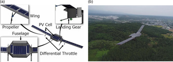
Figure 1 shows a full-wing solar-powered UAV with a wingspan of 7m and a fuselage of 1.2m. The UAV is powered by a twin propeller mounted on the wing, utilising an elevator placed at the rear of the fuselage for longitudinal control and a differential throttle for lateral control. At present, the UAV has completed several flights in different areas and altitudes, with a maximum flight endurance of 27h and a maximum flight altitude of 5,000m, with total flights exceeding 100 and total endurance exceeding 1,000h. With the long endurance verification completed, there are still some deficiencies that need to be further researched and improved, such as a more accurate state estimation algorithm(Reference Guo, Zhou, Zhu and Bai9), an optimal energy utilisation path planning(Reference Li, Sun and Li10,Reference Bolandhemmat, Thomsen and Marriott11) and a stable control in landing. Unlike a normal control scheme, which directly performs roll control by aileron or rudder(Reference Beard12), the differential throttle generates the yaw moment first and then the roll moment. When the UAV performs a right roll, the differential throttle directly produces a right yaw moment, then a left side slip occurs; as the vertical stabiliser is fixed under the wing, it produces a right roll moment. This indirect lateral control scheme reduces the lateral response speed and trajectory tracking accuracy. The scheme does not affect the autonomous control and path following in cruising, but there are more stringent runway restrictions and control accuracy requirements in landing, and the UAV is vulnerable to environmental factors.
Full-wing configuration solar-powered UAV. (a) 3D model. (b) Full-wing solar-powered UAV.

This UAV adopts the Total Energy Control System (TECS) and L1 control method for longitudinal and lateral trajectory tracking and a Proportion-Integration-Differentiation (PID) structure for inner loop control, which has been widely used in low-cost flight controller hardware (ArduPilot, Pixhawk)(Reference Oettershagen, Stastny and Hinzmann13). This control structure is applicable for longitudinal motion but is not suitable for the differential throttle control mode. To improve the control performance and increase the stability in landing, a more applicable path generation and following methods combined with its characteristics need to be explored.
There are several path following methods that have been proposed as the UAV guidance law that can be divided into two categories: geometry methods, and control techniques(Reference Sujit, Saripalli and Sousa14). The geometry methods include the line-of-sight (LOS), linear and nonlinear guidance law(Reference Zhao, Wang and Lin15), L1(Reference Park, Deyst and How16), and so on, which construct a visual waypoint and then force the UAV to track it. The control technology generates control commands according to the control theory and the characteristics of the UAV to ensure the cross-track error converges to zero, and the VF-based path following is a representative(Reference Beard, Ferrin and Humperys17). Due to its stable performance and easy implementation, the VF method has been widely used in a variety of unmanned vehicles. Nelson(Reference Nelson, Barber and McLain18) and Beard(Reference Beard and Mclain19) proposed a path following method based on the notion of VF and gave the proof of stability and showed that it can achieve stable trajectory tracking in windy conditions. Sujit compared the VF path following method with other guidance law and found that the VF has a lower cross-track error(Reference Sujit, Saripalli and Sousa14). Zhao completed the curved path following for a fixed-wing UAV based on the VF and proved the robustness and validity by the input-to-state-stable (ISS) properties(Reference Zhao, Wang and Lin15). Wilhelm also found that the heading angle guidance generated from VF is a candidate for obstacle avoidance implementation in windy conditions(Reference Wilhelm and Clem20). Fari demonstrated that the VF approach works perfectly for ideal first-order course angle dynamics and improved standard VF to compensate for wind uncertainty and unmodeled dynamics(Reference Fari, Wang, Roy and Baldi21). In path generation, the Dubins path has been proved to be time-optimal(Reference Beard and Mclain19) and widely applied in path planning for autonomous vehicles(Reference Belvins, Keshmiri, Shukla and Godfrey22). Manyam(Reference Manyam, Casbeer, Moll and Fuchs23) and Chen(Reference Chen24) studied the Dubins path from an arbitrary point to a circle and found that Circle Straight-line Circle (CSC) is optimal. Beard(Reference Owen, Beard and McLain25) extended the 2D Dubins path to 3D and designed a guidance law for the aircraft to follow a straight-line and helical paths. Singh(Reference Singh and Hota26) completed obstacle avoidance and path planning in a complex environment based on the 3D Dubins path and obtained the optimal CSC path.
The purpose of this paper is to address the problem in landing path following with a special control mode of the full-wing solar-powered UAV in real-life applications in order to improve the landing performance from the perspective of path following and generation. Inspired by the VF path following and Dubins path, this paper first applies the VF-based path following method to the outer loop of the lateral control and then proposes a landing path generation method with two novel 3D Dubins landing paths to improve the trajectory tracking accuracy and reduce the initial bias of approaching. Finally, a comprehensive simulation system including path generation, path following, control system and UAV module is established to complete the verification of different land paths. The results show that the combination of Dubins path and VF method achieves higher lateral control accuracy and it is suitable for the large-scale UAV with weak lateral control capability.
This paper is organised as follows. Section 2 introduces the practical multiple landing failures of the full-wing solar-powered UAV. The straight-line and orbit-path-following methods and applications are proposed in Section 3. Section 4 proposes the Dubins path-generation algorithm, and two landing path modes are proposed for the landing simulation. Section 5 presents the conclusion.
Different throttle control scheme.

2.0 PRACTICAL PROBLEM FORMULATION
The throttle command is composed of a base and a differential throttle. The former performs speed control, and the latter performs roll control. When the UAV is turning, the yaw moment is increased by increasing the differential throttle or the base throttle. The increase of the differential throttle directly increases the thrust difference between the left and right propellers, and the increase of the base throttle brings different thrust increments for the two propellers, as shown in Fig. 2. For example, when the UAV is cruising at an altitude of 3,000m with an airspeed 13m/s, a base throttle 0.57 and a differential throttle command 0.15 can produce a roll angle of 10°. However, during landing, the altitude is reduced to 20m above the ground, the airspeed is reduced to 9.5m/s, and the base throttle command is then reduced to 0.3. To achieve the same roll angle, the differential throttle command needs to be increased to 0.25 or the base throttle command increased to 0.4. The landing is an energy-consuming process with decreasing airspeed and altitude. The increase in throttle ensures that the UAV has sufficient turning ability, but the increase in total thrust injects energy into the system and ultimately increases airspeed or altitude. The increased energy cannot be dissipated in a short period of time, making it difficult to control the lateral distance, altitude and airspeed simultaneously. Especially under crosswind conditions, the lateral distance bias suddenly increases, and the differential throttle starts to oscillate and saturate, resulting in an “S-shape” trajectory, which eventually makes multiple landing failures, as shown in Figs 3 and 6.
Land flight data in the field test. (a) First six landing trajectories. (b) Last six landing trajectories.

Figure 3 shows the multiple failed landing paths in Gansu, China (102.358E, 34.258N). The flight took place on October 11, 2017, at a site altitude of 3,840m, a temperature of −10°C, a command airspeed of 15.0m/s and a crosswind speed of 5.5m/s on approach. After 11 failed landings, the trajectory tracking accuracy requirements were lowered and finally succeeded. The landing path was a rectangle (1,000 × 300m2) including 10 waypoints connected by nine straight-line paths, with the highest waypoint 50m above the ground, as shown in Fig. 4. The whole process was composed of climbing, altitude holding, descending, approaching, short approaching, flaring and finally taxiing to stop.
Typical rectangular landing waypoints and straight-line path.

In Fig. 4, A is the start or re-landing waypoint, and B to E are four waypoints of the four-sided route at the same altitude. After reaching E, the UAV starts to glide, and the FG and GH sections are the approaching and short approaching phases. When reaching G, the state of the UAV needs to be checked to ensure that it is safe after touching the ground. If the state parameters are within the range of the landing window, it turns to short approaching; otherwise, it climbs to A and starts re-landing. Figure 5 shows a typical landing window at G. This window is determined by the lateral distance, altitude and speed bias of 6m, 4m and 3m/s, respectively. In multiple failed landings, there is a crosswind near the landing window, causing the lateral distance bias of DC and FG to exceed the limit, as shown in Fig. 3. Table 1 summarises the parameters of the 12 landings. Under crosswind conditions, a smaller differential throttle command is insufficient for the lateral distance bias correction, resulting in an excess the lateral bias. However, a larger command causes the altitude or speed bias to exceed the limit, such as the 1st, 2nd, 4th and 9th landings. The large lateral bias at the beginning of approaching not only increases the difficulty of lateral control, but also leads to the coupling of lateral distance, altitude and airspeed control, resulting in multiple landing failures.
Land window at waypoint G.

State parameters in the multiple landings

According to Table 1, the lateral distance exceeds the limit seven times, the altitude exceeds the limit three times, and the airspeed exceeds the limit two times. The order of influence of landing window parameters: lateral distance > altitude > airspeed. Therefore, the lateral control accuracy is crucial for a successful landing. Figure 3 shows that the differential throttle control capability is insufficient and that the UAV is in an S-shapetrajectory in CD and EF.
Differential throttle control mode is easily coupled with the speed and altitude, which reduces the overall control accuracy. In addition, the limited control capability leads to throttle command saturation and oscillation when faced with a large initial lateral bias. Figure 6 shows the differential throttle comparison between a successful landing and a failed landing after approaching with a differential throttle limit is 0.3. The throttle command changes significantly with high saturation of the failed landing, while the command of the successful landing changes continuously with almost no saturation.
Successful and failed landing differential throttle comparison.

In general, the special configuration of the UAV brings benefits of excellent aerodynamic efficiency and optimal energy harvest and utilisation, but tailless and aileron-less design weakens the lateral damping. In addition, the different throttle control responds slowly, which is prone to oscillate and saturate. If there is a large lateral distance bias in approaching, the longitudinal parameters are easily coupled, and it is difficult to control the lateral distance, altitude and airspeed simultaneously. To make up for these defects of the UAV, this paper proposes two novel 3D Dubins paths and uses VF path following to improve landing performance.
3.0 VF PATH FOLLOWING METHOD
Figure 7 shows the lateral control structure of the UAV based on L1(Reference Park, Deyst and How16) and VF methods. The control flow is from the lateral distance to heading angle, then to roll angle, and finally to differential throttle. L1 guidance is a roll angle-based control method and VF path following is a heading angle-based control method. Because the differential throttle of a large-scale aircraft acquires a large yaw moment, a heading angle-based control method is more appropriate. Ma(Reference Ma, Zhu and Zhou6) used the VF method to improve the trajectory tracking accuracy in taxiing, and in this paper, the method is applied to the straight-line and orbit paths following of a full-wing solar-powered UAV.
Lateral trajectory tracking control structure.

Straight-line and orbit path following based on VF method. (a) Straight-line path following. (b) Orbit following.

Figure 8 shows the straight-line and orbit paths following based on the VF method, the red line represents the target path, and the blue arrow represents the heading command. The objective of the VF method is to construct a vector field to adjust the change of heading angle. When the lateral distance bias e
py
is large, the UAV is directed to approach the target path with reference heading angle
 ${\chi ^\infty } \in (0,\pi /2]$
, and when e
py
approaches zero, the UAV is on the target path and the desired heading angle is
 ${\chi _q}$
, as shown in Fig. 8(a).
3.1 Straight-line path following
The purpose of path following is to obtain the altitude command
 ${h_c}$
and heading angle command
 ${\chi _c}$
through the relative position of UAV and target path. Figure 9(a) shows several position vectors between the UAV and the target path, P
line
(r, q). Define r as the initial vector of the path, r = (r
n
, r
e
, r
d
)T; p as the current position vector of UAV, p = (p
n
, p
e
, p
d
)T; q as the unit vector of the target path direction, q = (q
n
, q
e
, q
d
)T; e
p as the relative path error vector, e
p
= p – r = (e
pn
, e
pe
, e
pd
)T; k
i as a unit vector in the downward direction; and s as the projection of e
p in the q-k
i plane, s = (s
n
, s
e
, s
d
)T.
Longitudinal straight-line path following. (a) Longitudinal straight-line path following. (b) Straight-line path following in q-k i plane.

Using the similar triangles in Fig. 9(b), it can be concluded that
 \begin{equation}\frac{{{h_c} - \left( { - {r_d}} \right)}}{{\sqrt {s_n^2 + s_e^2} }} = \frac{{ - {q_d}}}{{\sqrt {q_n^2 + q_e^2} }}\end{equation}
where s can be expressed as
 \begin{equation}{\bf{s}} = {{\bf{e}}_p} - \left( {{{\bf{e}}_p} \cdot {\bf{n}}} \right){\bf{n}}\end{equation}
n is the unit vector normal to the q-k i plane is calculated as
 \begin{equation}{\bf{n}} = \frac{{{\bf{q}} \times {{\bf{k}}^i}}}{{\left\| {{\bf{q}} \times {{\bf{k}}^i}} \right\|}}\end{equation}
Then,
 ${h_c}$
is given by
 \begin{equation}{h_c}\left( {{\bf{r}},{\bf{p}},{\bf{q}}} \right) = - {r_d} + \sqrt {s_n^2 + s_e^2} \left( {\frac{{ - {q_d}}}{{\sqrt {q_n^2 + q_e^2} }}} \right)\end{equation}
The course angle of P line (r, q) is given by
 \begin{equation}{\chi _q} = \arctan \frac{{{q_e}}}{{{q_n}}}\end{equation}
Due to reference heading angle
 ${\chi ^\infty } \in \left( {0,\left. {\pi /2} \right]} \right.$
, if e
py
approaches to zero,
 ${\chi _c}$
approaches to
 ${\chi _q}$
, and if e
py
approaches to infinity,
 ${\chi _c}$
also approaches to
 ${\chi _q} \pm {\chi ^\infty }$
. It can be written as
 \begin{equation}{\chi _c} = {\chi _q} - {\chi ^\infty }\frac{2}{\pi }\arctan \left( {{k_{path}}{e_{py}}} \right)\end{equation}
where
 ${k_{path}}$
is a positive constant that influences the rate of the transition from
 ${\chi ^\infty }$
to zero. The control characteristics of the UAV are sensitive to airspeed. To improve the stability of the heading angle change,
 ${k_{path}}$
is considered as a function of airspeed, and the equivalent heading angle gain
 $\overline {{k_{path}}} $
is introduced, as shown in Equation (7). The actual airspeed of the UAV ranges from 10 to 20m/s, and
 $\overline {{k_{path}}} $
for straight-line following is usually selected from 0.05 to 0.1.
 \begin{equation}{k_{path}} = \overline {{k_{path}}} /sat\left( {{V_a},{V_{\min }},\inf } \right)\end{equation}
3.2 Orbit path following
Figure 10 shows an orbital path following in the horizontal plane. The UAV is located at (p
n
, p
e
), the distance from it to orbit centre (c
n
, c
e
) is d, and the angular position from it to the orbit is
 $\varphi $
.
 $\chi $
is the heading angle, V
g
is the ground speed, and
 $\rho $
is the orbit radius.
Relative position of the UAV to orbit path.

The kinematics equation in the horizontal plane of UAV in an inertial coordinate system is given by
 \begin{equation}\left[ {\begin{array}{c}{{{\dot p}_n}}\\[4pt]{{{\dot p}_e}}\end{array}} \right] = \left[ {\begin{array}{c}{{V_g}\cos \chi }\\[4pt]{{V_g}\sin \chi }\end{array}} \right]\end{equation}
The velocity vector can be transformed into polar coordinates by multiplying a rotational matrix, described as
 \begin{equation}\left[ {\begin{array}{c}{\dot d}\\[4pt]{d\dot \varphi }\end{array}} \right] = \left[ {\begin{array}{c@{\quad}c}{\cos \varphi } & {\sin \varphi }\\[4pt]{ - \sin \varphi } & {\cos \varphi }\end{array}} \right]\left[ {\begin{array}{c}{{{\dot p}_n}}\\[4pt]{{{\dot p}_e}}\end{array}} \right] = \left[ {\begin{array}{c}{{V_g}\cos \left( {\chi - \varphi } \right)}\\[4pt]{{V_g}\sin \left( {\chi - \varphi } \right)}\end{array}} \right]\end{equation}
For a clockwise orbit, the desired course angle when the UAV is located on the orbit is given by
 ${\chi _q} = \varphi + \pi /2$
. Similarly, for a counter-clockwise orbit, the desired angle is given by
 ${\chi _q} = \varphi - \pi /2$
. When
 $d \gg \rho $
, the heading command is given by
 ${\chi _c} \approx {\chi _q} + \pi /2$
and the UAV is flying towards the orbit centre. Similarly, when
 $d = \rho $
, the desired course is given by
 ${\chi _c} \approx {\chi _q}$
and the UAV is flying tangent to the orbit. The course angle command is therefore given by
 \begin{equation}{\chi _c} = {\chi _q} + \lambda \arctan \left( {{k_{path}}\left( {\frac{{d - \rho }}{\rho }} \right)} \right)\end{equation}
where
 $\lambda = \pm 1$
, represents the clockwise or counter-clockwise direction. To ensure the desired heading angle
 ${\chi _c} \in \left( { - \pi ,\left. \pi \right]} \right.$
, Equation (10) is further written as
 \begin{equation}{\chi _c} = \varphi + \lambda \arctan \left( {{k_{path}}\left( {\frac{{d - \rho }}{\rho }} \right)} \right) + 2\pi n\end{equation}
where n is an integer, and
 $\overline {{k_{path}}} $
is selected from 0.1 to 0.2 when the UAV performs orbit following control.
Straight-line path-following simulation. (a) Trajectory tracking. (b) Trajectory tracking error.

3.3 Path following simulation
3.3.1 Straight-line path following verification
In this paper, a six-degree-of-freedom (6-DOF) model of the UAV is used for straight-line and orbit paths following verification. The initial conditions of straight-line path following are an altitude 600m, an airspeed 12.5m/s and a target path is start from (0, 0) to end of (−300, −600). The trajectory tracking and lateral distance bias of L1 and VF methods are shown in Fig. 11, with the gain parameters L
1 = 50m,
 $\overline {{k_{path}}} = 0.1$
, and
 ${\chi ^\infty } = \pi /6$
. The initial position of the UAV is (0, 0), and the velocity is in the positive direction along the x-axis. The solid line represents the real state, and the dotted line represents the estimated state from the sensor measurement to the Extended Kalman Filter (EKF) based data fusion model(Reference Guo, Zhou, Zhu and Bai9). Implementing sensor measurement and state estimation is to increase the credibility and fully analyse the source of error.
According to Fig. 11(a), both methods achieve straight-line path following and the UAV keeps a stable tracking state after point (−100, −200). The L1 method has a larger overshoot, with an “S-shaped” trajectory. The heading angle of the VF method changes gently, and the trajectory exhibits a damping characteristic. Figure 11(b) and Table 2 show that the maximum tracking error of both methods is the same. The VF method responds slowly but the lateral distance overshoot is reduced to 5m, and the overshoot of the L1 is 15.5m. The stable time of roll angle is shortened from 15 to 8s, and the stable heading angle bias is decreased from 3° to 1.2°. The distance estimation error of the two methods is nearly 1.5m, which is smaller than the stable control bias. However, L1 has a nearly 5m estimation error at 17s, which is located at the point (−80, −105), caused by the sudden change in the heading angle. Therefore, a larger bias not only reduces the accuracy of the path following, but also affects state estimation accuracy. In the straight-line path following, the heading angle-based VF method is more suitable for the UAV with differential throttle control.
Parameters of two path-following methods

3.3.2 Orbit path following verification
Using the same UAV model and initial conditions for simulation, the target orbit path is centred at (1, 1) and
 $\rho $
= 80m. The UAV follows it in a counter-clockwise direction with the initial point is at (0, 0) and the speed direction is along the positive direction of x-axis, and the gain parameters are: L
1 = 50m and
 $\overline {{k_{path}}} = 0.2$
. Figure 12 shows the path following results and lateral distance bias. The steady-state bias and steady response time of two methods are summarised in Table 2.
Orbit path-following simulation. (a) Trajectory tracking. (b) Trajectory tracking error.

The control accuracy of lateral distance bias, roll and heading angle of the two-orbit path-following methods is close. Figure 12(b) shows that the lateral distance stable error of L1 is 8.6m and VF is 6.5m. The respond speed and state estimation error of both methods are close, with a stable time 17s and lateral distance estimation error 1.3m. In straight-line path following,
 ${\chi _c}$
is fixed and the steady state error quickly approaches zero. However, in orbit path following,
 ${\chi _c}$
is changed and the response speed is slow, so the steady state error takes a long time to approach zero. The VF method improves the damping in trajectory tracking but cannot change the response speed. When a large initial lateral bias occurs from waypoint D to F, the application of VF alone cannot ensure the landing parameters meet the requirements. The landing control accuracy is not only related to the trajectory tracking method but also to the path pattern, and the landing path generation is another factor worth exploring.
4.0 DUBINS PATH-BASED LANDING TRAJECTORY GENERATION
The landing waypoints in Fig. 4 are switched through the relationship between the UAV position p and the waypoint position w
i. When
 $\left\| {{\bf{p}} - {{\bf{w}}_i}} \right\| \lt b$
, it is considered that the UAV reaches w
i and switches to w
i+1, where b is the threshold for waypoint tracking(Reference Beard and Mclain19). This waypoint switching method causes a sudden change in
 ${\chi _c}$
, leading to a large initial lateral distance bias. If the right-angle path from D to F in the landing path is changed to an arc,
 ${\chi _c}$
changes continuously, which avoids differential throttle saturation and control overshoot. This path between two different waypoints consisting of an arc, a straight line, and another arc to the final waypoint is a Dubins path. It is time and transition optimal(Reference Ambrosino, Ariola and Ciniglio27) and is suitable for the UAV with weak trajectory tracking ability.
4.1 Algorithm for Dubins path generation
The purpose of the Dubins path-generation algorithm is to construct a shortest Circular Straight-line Circular (CSC) path between two adjacent waypoints, then force the UAV to follow the path continuously until the last waypoint. The waypoint w is defined as (p,
 $\chi $
), with the start waypoint denoted as (p
s
,
 ${\chi _s}$
), and the end waypoint denoted as (p
e
,
 ${\chi _e}$
). The Dubins path consists of a start and an end arc of radius R and a straight line of length l. R is given by
 \begin{equation}R \ge {R_{\min }} = \frac{{V_g^2}}{{g\tan \left( {{\phi _{\max }}} \right)}}\end{equation}
where R
min is the minimum turning radius, which is derived by the maximum roll angle
 ${\phi _{\max }}$
and coordinated turn equation of UAV.
Total path length for four transition modes

Definition of three switching half planes for Dubins paths.

For any given start and end waypoints, there are four possible Dubins paths: right-hand arc starts to end of the right-hand arc (L-L), right-hand arc to left-hand arc (R-L), left-hand arc to right-hand arc (L-R) and left-hand arc to left-hand arc (L-R)(Reference Beard, Ferrin and Humperys17). Figure 13 shows the waypoint switching in L-R mode, where c
r
and c
l
represent the centres of the right and left-hand arcs, the subscripts s and e represent the start and end centres,
 $\vartheta $
is heading angle of start and end centres, and
 ${\vartheta _2}$
is the reference angle of
 $\vartheta $
. The centres of right- and left-handed circular arcs are obtained by p and
 $\chi $
are given by
 \begin{align}{{\bf{c}}_r} = {\bf{p}} + R{\left( {\cos \left( {\chi + \frac{\pi }{2}} \right),\sin \left( {\chi + \frac{\pi }{2}} \right),0} \right)^T}{\rm{ }}{{\bf{c}}_l} = {\bf{p}} + R{\left( {\cos \left( {\chi - \frac{\pi }{2}} \right),\sin \left( {\chi - \frac{\pi }{2}} \right),0} \right)^T}\nonumber\\\end{align}
These four path length calculation equations are listed in Table 3, where
 $R\left\langle \vartheta \right\rangle $
represents the arc length of
 $\vartheta $
. The Dubins path is then parameterised by a start circle c
s
with direction
 ${\lambda _s}$
, an end circle c
e
with direction
 ${\lambda _e}$
and three half-planes H
1
, H
2
and H
3
, as shown in Fig. 13. The UAV starts at an arc c
s; when enters H
1
, it tracks a straight line until it enters H
2
, when it switches to an orbit following at an arc c
e. After passing through H
3
, the waypoint is updated, and this process is repeated. The parameters of the half-plane H
i
are expressed as z
i and q
i, which represent position and normal vector. The parameters of Dubins path are therefore expressed as
 $\left( {L,{{\bf{c}}_s},{\lambda _s},{{\bf{c}}_e},{\lambda _e},{{\bf{z}}_1},{{\bf{q}}_1},{{\bf{z}}_2},{{\bf{z}}_3},{{\bf{q}}_3}} \right)$
. In the Dubins path waypoint switching, five states are defined to describe the CSC path from number 1 to 5, and they are switched according to the position of the UAV to the target path. State 1 represents UAV is tracking to the start waypoint, 2 represents it is on the arc of the left half-plane of H
1
, 3 represents it is on the straight-line section, 4 represents it is on the arc of the right half-plane of H
2
, and 5 represents it is on the arc of the left half-plane of H
3
. When it passes through H
3
, w
i switches to w
i+1 and the state restarts to 1.
Figure 14 is the flowchart of the Dubins path generation algorithm, which consists of initialisation, parameters update and state switching. Initialisation is to input the waypoint information and the current position of the UAV to obtain the centre position of the four CSC paths. Using angle() represents the angle between vectors, flag to distinguish different path modes, 1 represents the straight-line following and 2 represents the orbit following. The length of the four path modes is calculated according to Table 3, choosing the shortest one as the optimal and updating the Dubins path parameters. Then, the UAV is forced to track the CSC path through continuous state switching.
Dubins paths generation algorithm structure.

4.2 Landing trajectory generation algorithm
To improve the trajectory tracking accuracy of approaching, this paper uses a 3D helical path to replace the straight-line transition path of the E. Unlike the 2D path, the radius of the 3D helix is determined by the minimum turning radius of the UAV, the shape of the landing path and the continuity conditions of the waypoint transition. Figure 15 shows the different helical paths from DE to EF, with one or two helical paths are determined by the turning radius, R, and the length of DE, l DE . If R ≥ 1/2l DE , waypoints E and F are connected by a single helix, as shown in Fig. 15(a), and centred on O5; if R < 1/2l DE , the approaching path is similar to the L-L mode of the Dubins path, such as helices centred on O1 and O6.
Helical approaching path with different radii. (a) 2D arc path. (b) 3D arc path.

4.2.1 Case 1: Single helical landing path
Figure 15(b) shows the maximum and minimum radii of the helical path from waypoint D’ (E’) to F. When
 $R = {R_{\max }}$
, D’ and E’ are coincident. To ensure that the heading angle changes continuously, the tangential vector at point D’ (E’) is parallel to DE and the tangential vector at point F is parallel to EF. Therefore, in the single helical path generation, the radius needs to be determined first, derived as
 \begin{equation}\sqrt {l_{DE}^2 + h_{EF}^2} \gt R \ge \frac{1}{2}{l_{DE}}\end{equation}
This path is composed of a 3D helix and several straight-line paths, as shown in Fig. 16. The single helical path is the intersection of a cylinder surface with the centre O and an inclined surface ODF. Once the landing conditions are determined, D and F are also determined by the runway limitation and UAV performance. Then, the centre of the helix O and reference waypoint E’ are determined according to the height of EF and radius R h .
Single helix approaching landing path.

A time parameterised helical path is given by
 \begin{equation}{\bf{r}}\left( t \right) = {{\bf{c}}_h} + \left( {\begin{array}{c}{{R_h}\cos \left( {\lambda t + {\psi _h}} \right)}\\[4pt]{{R_h}\sin \left( {\lambda t + {\psi _h}} \right)}\\[4pt]{ - t{R_h}\tan {\gamma _h}}\end{array}} \right)\end{equation}
where
 ${\bf{r}}\!\left( t \right) = {\left[ {{r_n},{r_e},{r_d}} \right]^T}\left( t \right)$
is the position along the helical path,
 ${{\bf{c}}_h} = {\left[ {{c_n},{c_e},{c_d}} \right]^T}$
is the centre of the helix,
 $\lambda = \pm 1$
represents a clockwise and counter-clockwise helix,
 ${\psi _h}$
is the angle position of helix, and
 ${\gamma _h}$
is the desired flight path angle along the helix. The east and north component of Equation (15) is used to obtain
 \begin{equation}{\left( {{r_n} - {c_n}} \right)^2} + {\left( {{r_e} - {c_e}} \right)^2} = R_h^2\end{equation}
 \begin{equation}\tan \left( {\lambda t + {\psi _h}} \right) = \frac{{{r_e} - {c_e}}}{{{r_n} - {c_n}}}\end{equation}
Solving for t and plugging the inverse of Equation (17) into the third component of Equation (15) gives
 \begin{equation}{r_d} - {c_d} = - \frac{{{R_h}\tan {\gamma _h}}}{\lambda }\left( {{{\tan }^{ - 1}}\left( {\frac{{{r_e} - {c_e}}}{{{r_n} - {c_n}}}} \right) - {\psi _h}} \right)\end{equation}
Normalising the Equation (16) and (18) by R h results in a cylinder and an inclined surface equation
 \begin{align}{\alpha _{cylinder}}\left( {\bf{r}} \right) & = {\left( {\dfrac{{{r_n} - {c_n}}}{{{R_h}}}} \right)^2} + {\left( {\dfrac{{{r_e} - {c_e}}}{{{R_h}}}} \right)^2} - 1\nonumber\\[5pt]{\alpha _{plane}}\left( {\bf{r}} \right) & = \left( {\dfrac{{{r_d} - {c_d}}}{{{R_h}}}} \right) + \dfrac{{{R_h}\tan {\gamma _h}}}{\lambda }\left( {{{\tan }^{ - 1}}\left( {\dfrac{{{r_e} - {c_e}}}{{{r_n} - {c_n}}}} \right) - {\psi _h}} \right)\end{align}
The helical path is defined as
 \begin{equation}{P_{helix}}\left( {{{\bf{c}}_h},{\psi _h},\lambda ,{R_h},{\gamma _h}} \right) = \left\{ {r \in {\Re ^3}:{\rm{ }}{\alpha _{cylinder}}\left( {\bf{r}} \right) = 0\ \&\ {\alpha _{plane}}\left( {\bf{r}} \right) = 0} \right\}\end{equation}
Therefore, a single helical landing path is obtained by connecting A to D with three straight lines, D to F with a helix, and F to J with four straight lines.
L-L mode approaching landing path.

4.2.1 Case 2: L-L mode landing path
The L-L mode landing path is composed of several straight-line paths, three 2D arcs and a 3D helix, as shown in Fig. 17. All four waypoints from B to E are transitioned through a left-hand arc, where from E to F is a 3D helix. Similar to the single helical landing path, the radius of the L-L mode path also needs to be determined first. Equation (21) is the radius range of this path mode, where R is greater than the minimum radius and less than half of the length of DE.
 \begin{equation}\frac{1}{2}{l_{DE}} \ge R \gt \left\{ {\begin{array}{c}{\frac{{V_g^2}}{{g\tan {\phi _{\max }}}}}\\[6pt]{{d_{EF}}}\end{array}} \right.\end{equation}
For the 2D arcs at waypoints B, C, and D, the location of arc centre is directly determined by the waypoint position and radius, and each arc is tangent to the straight lines on the left and right sides of each waypoint; it is thus a quarter circle. For the 3D helical path at E, after the location of the helix centre is determined, the cylindrical surface
 ${\alpha _{cylinder}}\left( {\bf{r}} \right)$
and the inclined surface
 ${\alpha _{plane}}\left( {\bf{r}} \right)$
need to be determined according to Equation (19). Next, all waypoints are connected by straight line, arc and helix to generate the L-L landing path.
Different landing path generation diagram.

Figure 18 summarises the three different landing path generation processes, with the path mode is determined by R. A state variable CASE is introduced to describe different modes, with 0, 1, 2 represents straight line, single helical, L-L path. The landing process after E is composed of four stages, approaching, short approaching, flaring and runway taxiing, and the control laws of these stages are different. The approach control mode includes longitudinal descent and heading control, and the main difference with short approach is the glide path angle,
 ${\gamma _{app}}$
and
 ${\gamma _{sapp}}$
, generally
 $\left| {{\gamma _{app}}} \right| \gt \left| {{\gamma _{sapp}}} \right|$
. Before the short approach, the landing window states need to be checked and the entry condition is h = h G. The control law of the flaring includes vertical flare curve path following and roll angle hold, and the flaring path angle is given by(Reference Zhang and Wang28)
 \begin{equation}{\gamma _{flare}} = \arctan \frac{{[(1 - \varepsilon ){h_H} - {h_I}]\tan \eta }}{{\varepsilon {h_H}}}\end{equation}
where
 $\varepsilon $
is the gain of flaring and
 $\eta $
is the gliding angle of the reference glide path.
In the runway taxiing, the base throttle is set to idle throttle and the differential throttle controls heading angle until UAV stops. Four Boolean variables are defined to describe the landing state switches, LAND_NO_RETURN, if the state of UAV is within the landing widow limits, it switches to short approaching path; GO_AROUND, if the state exceeds the landing window limits, it returns to waypoint A and starts re-landing; FLARING, if LAND_NO_RETURN = TRUE and current reference altitude and airspeed are reduced to the flare altitude and speed, i.e. h = h flare and V = V TD , it follows the flare curve to touch down on the runway; TAXIING STOP, the UAV switches to runway taxiing control until stops to J.
4.3 Simulation verification
Figure 19 shows a complete full-wing solar-powered UAV simulator concept from path generation to following to flight control. The system is a continuous closed-loop structure composed of the top, middle and bottom layers. The path planning and management modules are the top layer, which consists of landing waypoints storage and path generation and output a straight-line or Dubins landing path. The path following and flight controller modules are the middle layer. The former consists of straight-line and orbit paths followed by VF and L1 methods, and the latter consists of sensors, state estimation and control laws at different stages. This layer generates altitude, airspeed and heading angle commands according to the relationship between the UAV position and the target path, and then output the actuator commands through the flight controller. The UAV module is the bottom layer composed of environment, energy system, aerodynamic force, gravity, ground taxiing and 6-DOF equation of motions (EOM) that outputs and displays the full state. The wind field and runway conditions are set in the environmental model. The energy system of the UAV consists of PV cells, MPPT and batteries for energy collection, consumption and storage. Based on this platform, this paper has completed the simulation of 2D “8-shape” path and three different 3D landing paths.
Mission waypoints information

Component-level simulation system concept.

4.3.1 2D Dubins path simulation
In this verification, an 8-shape mission path starting from (0, 0) and finally back to initial point is designed as the target, and the five waypoints are listed Table 4. This path has a larger heading angle command change and a greater lateral distance bias at waypoint switching. The simulation conditions are an altitude command 600m, an initial speed 12.5m/s, a cruise speed 13m/s, a crosswind in the x-direction 3m/s and a simulation time 180s. The trajectory tracking, heading angle and roll angle of the straight-line and Dubins path are shown in Fig. 20, and the tracking error is summarised in Table 5.
Parameters of straight-line and Dubins 8-shape path following. (a) Straight-line mode path following. (b) Dubins path mode path following. (c) Heading angle of straight-line mode. (d) Heading angle of Dubins path mode. (e) Roll angle of straight-line mode. (f) Roll angle of Dubins path mode.

Roll angle, heading angle and trajectory tracking error

The results show that the state estimation error is considerably smaller than the control bias and can be ignored. The Dubins path is better than straight line in lateral control, mission area coverage, roll angle and heading angle tracking. Figure 20(a, b) and Table 5 show that there is a clear deviation between the straight-line path and target path, with the lateral distance bias is the largest when the waypoint is switching, 110m for the straight-line path and 53m for the Dubins mode, with less overshoot. Figure 20(c, d) indicates that the Dubins path avoids the sudden change of the heading angle command and changes it to a slope line. The accuracy of heading angle is significantly improved, with the average heading tracking error is reduced from 10.6° to 4.7°. Because the roll control is indirect, the roll angle accuracy of the two is close, but the Dubins path is less saturated. The continuous change of the heading angle during waypoint switching compensates for the indirect control mode, avoids saturation of the differential throttle, and effectively improves the accuracy of the trajectory tracking.
Land waypoints information

4.3.2 Straight-line and single helical landing paths simulation
Table 6 shows the 10 landing waypoints with the runway altitude of 550m, length of 300m and width of 50m, as shown in Fig. 21(a). The initial position of the UAV is at the re-landing waypoint with a landing airspeed of 13m/s, an approach airspeed of 11m/s, an eastward crosswind of 3m/s, a differential throttle limit of 0.25 and a simulation time of 165s.
Two kinds of landing paths simulation. (a) Straight-line landing path. (b) Single helical approaching landing path.

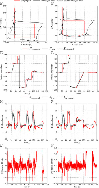
Figure 21 shows straight-line and single-helical landing paths following simulation results, and 2D landing path, heading angle, roll angle and differential throttle are shown in Fig. 22. The difference between the two is in the approach phase, where the corresponding simulation time is from 85 to 120s. The state of the UAV on the straight-line landing path at waypoint G exceeds the landing window limits, while the state of the helical path is within the limits. Since the re-landing procedure is not executed in simulation, both UAVs finally land on the runway. According to Fig. 22(a), the lateral distance bias gradually increased from B to E. The bias at E is 87m and that at G is 26.5m, which is considerably larger than the lateral bias limit. As shown in Fig. 22(g, h), the large initial lateral distance bias leads to the differential throttle susceptible to saturation and results in a significant altitude control bias between the true and the target approaching path, as shown in Fig. 22(a). Table 7 summarises the estimated and true state tracking errors of the landing window, and the state estimation error is much smaller than the control bias. The estimated error of altitude, airspeed, lateral distance and attitude angle are 0.4–1.8m, 0.5–1.2m/s, 2.1–3.5m, and 0.5°–2°, respectively. It should be noted that a larger lateral distance bias causes a larger estimation error and affects the parameter accuracy near the landing window, which is consistent with the phenomenon-of multiple landing failures in Section 2.
Parameters of straight-line and Dubins landing path following. (a) 2D straight-line landing path following. (b) 2D single-helix landing path following. (c) Heading angle of straight-line mode. (d) Heading angle of single-helix mode. (e) Roll angle of straight-line mode. (f) Roll angle of single-helix mode. (g) Differential throttle of straight-line mode. (h) Differential throttle of single-helix mode.

The single helical landing path uses a helix from waypoint D to E as a transition of approaching, shown in Fig. 21(b). The lateral distance bias at E and G in Fig. 22(b) are 9.7 and 3.9m, and the altitude control bias of the two waypoints is 4.8 and 3.6m, which are much smaller than the straight-line path. The trajectory tracking accuracy of this mode is better, with the airspeed, altitude and lateral distance bias all meet the requirements. Figure 22(c, d) show that the heading angle command of the turning at D and E is changed from abruptly increasing to a slope line, which reduces the speed requirements for lateral control and keeps a stable tracking of the heading, similar to Fig. 20(d). Figure 22(f) shows that the roll angle command is reduced to 9° and the stable time is extended to 30s, indicating that a slow change and stable tracking of the heading angle reduces the roll angle command and extends the control time. The single helical path converts the sudden change of heading angle command into a continuous slow change, which makes up for the weak control capability of the differential throttle and reduces the initial lateral distance bias of approaching. Due to the large lateral distance bias of CD, a large differential throttle command is required in correction of the bias and heading tracking, and the differential throttle of two paths are saturated, as shown in Fig. 22(g, h). Therefore, this mode does not change the saturation of the differential throttle.
4.3.3 L-L mode landing path simulation
Under the same input condition, the L-L mode landing path of Fig. 17 is used as the target path for landing simulation comparison. The true and estimated landing paths are shown in Fig. 23, and 2D landing path, heading angle, roll angle and differential throttle are shown in Fig. 24. The overall path following accuracy is significantly better than the straight-line path in Fig. 22(a). Table 7 shows that altitude, airspeed and lateral distance bias of this path at waypoint G are 3.3, 2.1 and 3.0m, which meet the landing window requirements. Finally, the UAV successfully landed on the runway.
Control error of three landing paths simulation at waypoint G

L-L mode approaching landing path simulation.

L-L mode landing-path simulation. (a) 2D L-L mode landing-path following. (b) Heading angle of L-L mode path. (c) Roll angle of L-L mode path. (d) Differential throttle of L-L mode path.

The lateral distance bias at waypoints C, D and E in Fig. 24(a) are 32.1, 10.5 and 33.6m, which are nearly half of that in Fig. 22(a), ensuring that the bias at G does not exceed the limit. Compared with the single helix path, each arc path of the L-L mode is shortened, equivalent to reducing the time of the lateral distance correction. The lateral bias of DE of these two modes is close, and the L-L mode has a larger bias in EF. Figure 24(b) shows that L-L mode achieves a stable tracking of the heading angle by switching the heading angle command at each waypoint from suddenly changing to a short slope line. Both Dubins modes are effectively improve the control accuracy of the heading angle. The single helix mode is to merge the heading angle command from D to E into a slope line, and the L-L mode converts the heading angle command of each waypoint separately. Table 7 shows that the heading angle and lateral distance tracking accuracy sequence of the three modes are single helical mode > L-L mode > straight-line mode. The sudden change of the roll angle command in Fig. 24(c) is reduced, the roll angle control accuracy is improved compared to Fig. 20(e), and the differential throttle command in Fig. 24(d) is almost not saturated.
In general, the reasons for the landing failure of the straight-line mode in a crosswind condition are a weak lateral capability cannot eliminate a large initial lateral bias at the beginning of approaching, and differential throttle coupled with speed and height control causes the UAV deviates from the target path. In addition, a larger bias also increases the state estimation error, which is consistent with the practical landing failure. For large-scale UAVs with weak lateral control capability, the application of the VF method improves the tracking accuracy of the straight-line path within a certain range, and the landing path mode is another important factor worth exploring. Two types of Dubins landing paths reduce the control bias at the beginning of approaching, improving the lateral distance control accuracy, and increasing the chance of successful landing. The lateral control accuracy of the single helix mode is higher and more suitable under the conditions of the complex wind field or higher requirements for lateral control accuracy. The L-L mode is regarded as dividing a single helix into multiple arcs, which effectively improves the overall tracking accuracy of landing and avoids saturation of the differential throttle command.
5.0 CONCLUSIONS
Multiple landing failures indicate that a large initial lateral distance bias at the beginning of the approach causes saturation of the differential throttle and leads to an S-shaped trajectory. Moreover, a large differential throttle command is easily coupled with airspeed and altitude control, making the parameters exceed the limit. In addition, a large control bias increases state estimation error, which also reduces the accuracy of landing control.
The heading angle-based VF path following is more suitable for the large-scale UAV with a differential throttle. This method only increases the control damping without changing the response speed. Therefore, the benefits of applying it alone in trajectory tracking are limited, and the modes of landing path needs to be redesigned.
The Dubins path effectively reduces the initial control bias during waypoint switching, improves the accuracy and stability of the heading angle control and avoids a command suddenly changing. The proposed two Dubins landing paths can reduce the initial lateral control bias of approaching, thereby improving the chance of successful landing. The single helix mode has the highest lateral distance control accuracy after approaching, and the L-L mode improves the overall control accuracy and avoids saturation of differential throttle. The redesigned 3D Dubins landing paths and its generation method are applicable for the UAV with weak lateral control capabilities. In the next step, we plan to load the VF path following and Dubins landing path into the controller of the full-wing solar-powered UAV for real landing test to complete the validation of the proposed algorithms.
Acknowledgements
This work was supported in part by the Equipment Pre-research Project of China under Grant 41411010401, the National Key R&D Program in Shaanxi Province under Grant 2018ZDCXL-GY-03004, and the Innovation Program of Research Institutions under Grant TC2018DYDS24. The authors would like to express their sincere gratitude to the editor-in-chief, the guest editors and the anonymous reviewers whose insightful comments have helped to improve the quality of this paper considerably.
SUPPLEMENTARY MATERIAL
To view supplementary material for this article, please visit https://doi.org/10.1017/aer.2021.26