I. INTRODUCTION
Over more than 30 years, monolithic alumina is being used as the bearing component in hip prosthetic devices due to its superior wear resistance, chemical durability, and bio-inertness, Reference Hamadouche, Boutin, Daussange, Bolander and Sedel1,Reference Sedel and Kokubo2 but it is liable to fracture. To improve its reliability, stabilized zirconia Reference Clarke, Manaka, Green, Williams, Pezzotti, Kim, Ries, Sugano, Sedel, Delauney, Ben Nissan, Donaldson and Gustafson3 or zirconia–alumina composites Reference Begand, Oberbach and Glien4,Reference Burger and Richter5 with high fracture toughness have been fabricated. However, the possibility of fracture of these composite ceramics cannot be eliminated. These disadvantages have spurred exploration of thin zirconia ceramic layers on metallic substrates as an alternative to monolithic ceramics. For this purpose, a ∼5 µm thick layer of zirconia was formed on the surface of a Zr–2.5% Nb alloy using heat treatment at 500 °C. Reference Hobbs, Rosen, Mangin, Treska and Hunter6 This hybrid design of the zirconia layer on the Zr–Nb alloy has been successfully applied to a femoral head, commercialized as Oxinium™ (Smith & Nephew, Memphis, Tennessee). However, some reports have revealed the extensive damage and delamination of zirconia layer during bearing operations. Reference Evangelista, Fulkerson, Kummer and Di Cesare7,Reference Jaffe, Strauss, Cardinale, Herrera and Kummer8 In some cases, ultra-hard ceramic layers of diamond-like carbon Reference Lappalainen, Anttila and Heinonen9,Reference Choudhury, Lackner, Major, Morita, Sawae, Bin Mamat, Stavness, Roy and Krupka10 or titanium nitride Reference Pappas, Makris and Buechel11 have been fabricated on Ti–6Al–4V alloy. However, both of these layers showed poor adhesion with the substrate and released wear debris enhanced third body wear which has limited their use for long term structural applications in industry. Reference Hauert, Falub, Thorwarth, Thorwarth, Affolter, Stiefel, Podleska and Taeger12,Reference Raimondi and Pietrabissa13
In this perspective, we previously proposed a new hybrid approach that combines superior wear resistance of ceramics with superior mechanical strength and fracture toughness of metals by forming a dense layer of α-alumina onto Ti–6Al–4V alloy. Reference Khanna, Kokubo, Matsushita, Nomura, Nose, Oomori, Yoshida and Takadama14,Reference Khanna, Kokubo, Matsushita and Takadama15 Alumina was chosen as the surface layer due to its superior wear resistance as compared with zirconia; Ti–6Al–4V alloy was chosen as the substrate material due to its high mechanical strength and fracture toughness as compared with Zr–Nb or Co–Cr alloys. Surface modification of Ti alloy substrate by a thin layer of dense alumina can be beneficial to retain superior wear resistance of alumina and mechanical strength of the Ti alloy which in turn can improve poor toughness of alumina and wear resistance of the Ti alloy simultaneously. To address the critical issue of failure of ceramic coatings on metal due to residual stress at the interface, it is hypothesized that the adhesion between the ceramic layer and metal substrate might be improved if a thin and dense reaction layer with metallurgical bond-like characteristics can be formed at their interface. In this regard, previously we demonstrated that a thin, dense reaction layer of Al3Ti intermetallic compound at the interface is needed to improve adhesion. Reference Khanna, Kokubo, Matsushita, Nomura, Nose, Oomori, Yoshida and Takadama14,Reference Khanna, Kokubo, Matsushita and Takadama15 A reaction layer with gradient compositions could further promote adhesion and reliability of the ceramic-metal joint. Reference Khanna, Kokubo, Matsushita, Nomura, Nose, Oomori, Yoshida and Takadama14
Conventionally, alumina layers are deposited on metals by plasma spraying of α-alumina powders. However, plasma sprayed alumina contain porous microstructures with predominantly γ-alumina phase. Moreover, dense α-alumina is very difficult to form directly on the Ti alloy since it requires high sintering temperatures Reference Trunov, Schoenitz, Zhu and Dreizin16 above 1200 °C and such high temperatures cannot be applied to Ti–6A–4V alloy because heat treatment at 995 °C transforms α → β Ti, that results in decrease in the mechanical strength of the alloy, which defeats the purpose of using high strength Ti alloy. Reference Semiatin, Seetharaman and Weiss17 To overcome these problems, we previously proposed to a new processing method to form alumina layer on the Ti alloy by formation of dense Al layer by cold spraying, followed by a heat treatment at 640 °C in air to form a reaction layer at the interface to improve adhesion and finally, micro-arc oxidation (MAO) treatment to transform Al to dense alumina layer with high Vickers hardness ∼1900 HV. Reference Khanna, Kokubo, Matsushita and Takadama15 In this work, we explore the alternate cost-effective methods of depositing Al on the Ti alloy which could show potential to adhere strongly with the substrate without additional heat treatments deemed necessary previously Reference Khanna, Kokubo, Matsushita, Nomura, Nose, Oomori, Yoshida and Takadama14,Reference Khanna, Kokubo, Matsushita and Takadama15 which could also reduce the cost of manufacturing of our advanced hybrids. In this regard, weld cladding is a commonly used method to deposit metal coatings on the substrates using Gas Metal Arc Welding (GMAW), or Laser cladding. However, dilution is a key concern in these methods. A higher dilution results in mixing of the metal substrate with the material to be deposited, leading to change in chemistry of the coated material and could adversely affect the thickness of intermetallics formed at the interface between the coating and the substrate in case of Al/Fe, Al/Ti coating/substrate systems. It is noteworthy that for a good reliability of the designed alumina/Ti alloy hybrid, thickness of intermetallic layer should be less than 5 μm which otherwise can result in cracks within the AlTi intermetallics Reference Xu, Cui, Hao and Yang18 and/or at the interface between alumina and the Ti alloy. A promising alternative to minimize dilution is to use a low heat input method which could result in minimal diffusion of the substrate material into the coating thereby forming a thin layer of intermetallics. Due to a very low heat input process, cold metal transfer (CMT) method has been shown to result in 2–4 µm thick intermetallic layers in joints of Al and Zn-coated steels. Reference Zhang, Feng, He, Zhang, Chen and Wang19 CMT is a modified GMAW method characterized by low heat input and is the chosen method in this work to deposit thick Al coatings on the Ti alloy. CMT method has been used in joining Al with Ti, Reference Cao, Sun and Chen20 Cu, Reference Cai, Ai, Cao, Lin and Chen21 Ti and Cu Reference Cao, Feng and Chen22 and Al–Si–Mn alloy layer on pure Al plate. Reference Rajeev, Kamaraj and Bakshi23 However, CMT method has not been used to deposit Al layer on the Ti alloys yet, which requires process optimization.
Furthermore, to oxidize Al metal, we used micro-arc oxidation (MAO) method, a plasma-assisted electrochemical surface treatment that combines electrochemical oxidation with a high voltage spark treatment (400–700 V) to form dense oxide layers. Reference Krishna, Somaraju and Sundararajan24–Reference Yerokhin, Shatrov, Samsonov, Shashkov, Pilkington, Leyland and Matthews26 MAO treatment of pure Al plates forms a graded oxide layer with mainly γ-alumina at outer surface and with increasing depth, the amount of γ-alumina decreases and α-alumina increases and mainly, dense α-alumina is formed in innermost regions. Reference Khanna, Kokubo, Matsushita and Takadama15,Reference Krishna, Gupta and Sundararajan27 For tribological applications, outer porous regions of oxide layer containing mixed α and γ-alumina must be abraded to expose underlying dense functional layer of α-alumina with high hardness. The specific objectives of this work are: to deposit thick and dense layers of pure Al on the surface of Ti–6Al–4V alloy by CMT method (a); to determine the possibility of reaction layer formation during Al deposition itself (b); to oxidize deposited Al layers to dense alumina layers on the Ti alloy by MAO method (c).
II. MATERIALS AND METHODS
A. Materials
Ti–6Al–4V alloy plates, 2 mm in thickness were used as substrates. Commercially pure AA1100 Al wire 1.2 mm in diameter was used for deposition of Al layers on the Ti alloy by CMT method. Electrolytic solution for MAO treatments was prepared using sodium meta-silicate and potassium hydroxide.
B. Deposition of Al layer on Ti–6Al–4V alloy substrate using CMT method
Al layer was deposited on 2 mm thick Ti–6Al–4V plate using CMT method using 1.2 mm diameter AA1100 wire electrode. A CMT Trans plus Synergic 4000 equipment (Fronius International GmbH, Wels, Austria) mounted on a linear carriage was used with a welding speed of 40 mm/min with a continuous flow of Ar gas at a flow rate of 12 L/min to deposit the Al coating by deposition of over-lapping beads. Several 10 cm long Al beads were deposited on the Ti alloy plate to form Al coating. The wire feed rate was changed from 2.6 to 3.7 m/min and arc force correction was kept around 2.5–3.0 and its effect on the shape of the bead was observed. The current (40–60 A) and voltage (10.8–11.5 V) were automatically set by the program in the microprocessor. The optimal parameters were chosen for depositing the Al coating. The deposited coating was processed further for MAO studies.
C. Micro-arc oxidation treatments
CMT-Al/Ti samples were cut into 15 ×10 × 2 mm3 in size and the CMT-Al layer was abraded with #400 diamond plates to thickness of ∼50–150 μm, and subsequently, cleaned using an ultra-sonicator for 10 min in acetone and dried in air. Fresh alkaline electrolytic solution containing 2 g/L sodium meta-silicate and 1 g/L potassium hydroxide was prepared using deionized water. The pH of the electrolytic solution was 12.38. For MAO treatments, a customized bipolar pulse power supply was used as reported elsewhere. Reference Matsushima, Noda, Yoshida, Kato, Kalita, Kizuki, Uchida, Umeno and Wakita28 The CMT-Al/Ti sample was connected to the anode and a separate Al plate was connected to the cathode using clips. Cleaned CMT-Al/Ti samples were immersed in prepared electrolytic solution in an electrolysis tank of stainless steel. The electrolytic solution was mixed thoroughly by a magnetic stirrer for the entire duration of MAO treatments. The temperature of the electrolytic solution was maintained below 40 °C by a water cooling system during the MAO treatments. The optimal electrical parameters of 500 Hz pulse frequency, 60% duty cycle, positive current density of 1.5 A/cm2, and treatment time of 60 min were used following our previous study Reference Khanna, Kokubo, Matsushita and Takadama15 and used in all the experiments. After all the MAO treatments, the samples were taken out of the electrolytic solution, washed thoroughly in cold running water, ultrasonically cleaned in acetone for 5 min and air-dried before performing materials characterization. At least three samples were used for MAO treatment at each set of parameters and all the experiments were repeated at least three times to ensure repeatability and reproducibility, and representative data was reported.
D. Materials characterization
Phase analyses of the surface of samples were performed by a thin film X-ray diffractometer (TF-XRD; RINT 2500, Rigaku Corporation, Tokyo, Japan). Sequential TF-XRD, abrasion, and optical microscopy observations were performed to reveal the structure of alumina with increasing depth from the outer surface of oxide layer formed by MAO of CS-Al/Ti. Phases of oxide layers were matched with standard JCPDS # 004-0787 for Al, JCPDS # 010-0425 for γ-alumina and JCPDS # 01-083-2080 for α-alumina. The microstructures of CS-Al/Ti after MAO treatments were observed using a field emission scanning electron microscope (FE-SEM; S4300, Hitachi Corporation, Tokyo, Japan, and Inspect-F, FEI Company, Hillsboro, Oregon) using secondary and back-scattered electron mode, denoted as SE and BSE, respectively. The X-ray elemental mapping was performed by an energy dispersive X-ray spectrometer (EMAX-7000, Horiba Ltd., Kyoto, Japan).
E. Hardness measurements
The hardness measurements of oxide layer samples containing mainly α-alumina in their inner-most region, were performed by Vickers indentation method. To determine the thickness of the α-alumina layer in MAO treated sample, outer oxide layers containing a mixture of γ and α-alumina were carefully removed by abrasion, followed by TF-XRD to confirm the formation of α-alumina and subsequently, observed under the optical microscope to measure the thickness. Subsequently, Vickers indentations were performed at a load of 980.7 mN with a dwell time of 10 s, within the α-alumina layer on the mirror-polished cross-sectional samples.
III. RESULTS AND DISCUSSION
A. Deposition and microstructure of CMT Al coated Ti alloy
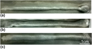
Figure 1 shows the beads deposited at low and high wire feed rates of 2.6 and 3.7 m/min respectively. It is observed that at lower wire feed rate of 2.6 m/min (current = 40 A), thin nonuniform beads were deposited, as shown by a typical image in Fig. 1(a). At a higher wire feed rate of 3.7 m/min (current = 60 A), thicker beads were observed. But these beads were larger and rounder in shape indicating poor wetting characteristic, as shown by a typical image in Fig. 1(b). Decreasing the wire feed rate to 3.5 m/min (current = 55 A) and increasing the arc force correction to +2.5 resulted in visibly improved wetting as shown by a typical image in Fig. 1(c). This parameter was used for depositing the Al coating on the Ti alloy which was further used for MAO treatment. It is noted that as the welding progresses, the substrate temperature increases and this improved the wetting. The exact mechanism of improvement in wetting and the effect of these parameters require the study of their effect on the variation of current and voltage during each CMT cycle and is outside the scope of the present work.
Picture of beads deposited using different welding parameters. (a) Wire feed rate = 2.6 m/min, arc force correction = 0; (b) Wire feed rate = 3.7 m/min, arc force correction = 0 and (c) Wire feed rate = 3.5 m/min, arc force correction = +2.5.

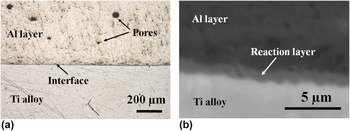
Figure 2(a) shows the picture of the cross-section of deposited Al layer on Ti alloy substrate. Close observations within the CMT-Al layer revealed almost dense microstructural regions with a few irregular and circular pores about 20–50 µm size trapped within the outer regions of the layer, as shown in optical micrograph, Fig. 2(a). It is commonly known that pores in Al welds are due to higher solubility of hydrogen in molten Al that are released upon solidification. Nevertheless, inner regions of CMT-Al layer i.e., within 150 μm from the interface did not reveal big pores. This is due to the fact that the solidification of the bead progresses from the substrate to the surface which leads to accumulation of hydrogen in the liquid closer to the surface. Furthermore, CMT-Al layer appears to have good adhesion with the Ti alloy since there were no gaps or cracks seen at the interface between the layer and the substrate. High magnification BSE image of cross-section of CMT-Al/Ti sample near the interface between CMT-Al layer and the Ti alloy in Fig. 2(b), revealed three regions-dark gray (top), gray (middle), and light gray region (bottom) which corresponds to CMT-Al layer, reaction layer, and the Ti alloy, respectively. The thickness of reaction layer appears to be about 1.5 μm. As shown in Fig. 2(b), the reaction layer appears to be dense and no cracks are observed at the interface which suggests a good adhesion between the CMT-Al layer and the Ti alloy.
(a) Optical micrograph of cross-section of CMT-Al/Ti showing almost dense, adherent CMT-Al layer formed on the Ti alloy; (b) High magnification BSE image of the cross section showing thin reaction layer at the interface between CMT-Al layer and the Ti alloy substrate.

B. Characterization of the reaction layer between CMT-Al layer and the Ti alloy
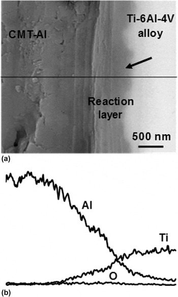
To understand the underlying mechanism of good adhesion of CMT-Al layer with the Ti alloy substrate, compositional analyses by EDS and phase characterization by thin film XRD (TF-XRD), were performed near the interface. High magnification BSE image of cross-section of CMT-Al/Ti clearly revealed the composition contrast near the interface between reaction layer and the Ti alloy, as shown by an arrow in Fig. 3(a). EDS line profile plot in Fig. 3(b) and compositional data, revealed gradient elemental profiles in Al and Ti in which Al was gradually decreased and Ti gradually increased across CMT-Al-Reaction layer-Ti alloy which suggests gradient compositions of intermetallic structures rich in Al (90.6% Al, 2.41% Ti, and 6.97% O) on Al side, vary gradually across the interface as (87.8% Al, 7.2% Ti; 5.0% O), (67.4% Al, 20.7% Ti, 11.9% O); (50.4% Al, 34.8% Ti, 14.9% O), and rich in Ti (11.9% Al, 82.3% Ti, 5.7% O) on Ti side. Elemental ratio of Al/Ti of within the reaction layer is about 3/1, that indicates the possibility of formation of Al3Ti intermetallic compound within the reaction layer. In addition, small amount of O ∼12–15% was also detected mainly close to or within reaction layer which suggests the possibility of small amount of oxides composed of Al, Ti, O elements, which might have formed due to high activity of oxygen during welding of Al with Ti alloy. It is noteworthy that a small amount of oxygen is necessary to promote adhesion between the layer and the substrate. Reference Borbidge, Allen and Whelan29 Characterization of interface structures by TEM is expected to reveal the structure of oxides within the reaction layer, which is outside the scope of this work.
(a) BSE image of cross-section of CMT-Al/Ti showing CMT-Al layer, Reaction layer and Ti alloy; (b) EDS line profile showing gradient elemental profiles in Al and Ti across interfaces between CMT-Al, Reaction layer and the Ti alloy.

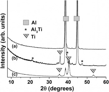
To reveal the phase of reaction layer, attempts were made to remove the top CMT-Al layer by abrasion, followed by TF-XRD directly on the surface of reaction layer. Due to thin reaction layer, it was abraded away along with CMT-Al layer even with the careful abrasion. To detect the phase of reaction layer, CMT-Al layer was not abraded completely, instead incident angle of TF-XRD was changed to 3° which revealed phase of reaction layer in addition to phases of top CMT-Al and underlying the Ti alloy substrate, as shown in TF-XRD patterns in Fig. 4. TF-XRD pattern of top surface of CMT-Al layer revealed the characteristic peaks of Al at 38.74°, 44.67° 2θ in Fig. 4(a), which matched with standard JCDS pattern # 00-004-0787. TF-XRD pattern of partially abraded CMT-Al layer clearly revealed the small intensity peaks at 2θ = 20.7°, 39.2°, 42.4°, and 47.3° which corresponds to Al3Ti phase according to standard JCPDS pattern #00-037-1449 in Fig. 4(b). TF-XRD was performed onto the Ti alloy substrate as shown in Fig. 4(c), to characterize the additional small peaks that appeared in Fig. 4(b), due to detection of Ti alloy substrate underneath the thin reaction layer.
(a) TF-XRD patterns showing characteristic peaks of (a) CMT-Al layer, (b) CMT-Al and reaction layer and (c) Ti alloy substrate, respectively.

Overall, microscopic observations, compositional and phase analyses suggest that a thin reaction layer composed of Al3Ti intermetallic compound was formed in situ during deposition of Al on the Ti alloy by CMT method. Intermetallic structure of Al3Ti seems to be formed by diffusion of Al into Ti during welding of Al on Ti alloy which seems to be thermodynamically feasible as Al3Ti starts forming above 525 °C. Reference Xu, Cui, Hao and Yang18 Our EDS composition data showed the possibility of presence of structures with gradient compositions in Al, Ti, and O, especially within and near the reaction layer, which were not detected by TF-XRD due to probably their small amounts. In our previous work, similar kind of reaction layer of Al3Ti intermetallic compound was formed by deposition of Al layer onto the Ti alloy by cold spraying, followed by a heat treatment at 640 °C for 1 h in air or Ar gas atmosphere. Reference Khanna, Matsushita, Kokubo and Takadama30 Comparing previous results of reaction layer Reference Khanna, Kokubo, Matsushita, Nomura, Nose, Oomori, Yoshida and Takadama14 with current results, dense reaction layer between CMT-Al and the Ti alloy can be formed directly in situ by deposition of Al layer by CMT method without requiring an additional heat treatment, which is a new finding.
C. Characterization of oxide layer formed by MAO of CMT-Al layer
1. Microstructural analysis by SEM imaging/EDS
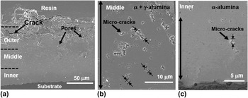
BSE image of the cross-section of CMT-Al/Ti after MAO treatment for 60 min showed three regions of the oxide layer; an outer porous region, a middle dense region and inner dense region in Fig. 5(a). The total thickness of oxide layer was about 100–120 μm containing outer region ∼40–50 μm thick, middle region ∼38 μm thick and inner region ∼30 μm thick. With increasing depth from outer to inner regions of the oxide layer, gradual variation in microstructures was observed. For instance, outer regions were composed of porous microstructures with big cracks and irregular pores as shown in SEM image, Fig. 5(a). Relatively dense microstructures with micro-cracks in the range of about 0.5–4.2 μm in size were observed in middle regions as shown in high magnification cross-sectional SEM image, Fig. 5(b). It is noteworthy that within middle regions of oxide layer, gradients in micro-crack size and distribution was observed as shown by almost gradual decrease in size range of micro-cracks from a broad range of ∼0.5–4.2 μm to ∼0.5–1.6 μm. With increasing depth, size of micro-cracks was skewed more toward 0.5 μm in bottom regions in cross-sectional SEM image, Fig. 5(b). With further increasing depth, almost dense microstructure with only a few tiny micro-cracks in the range of 0.2–1.4 μm in size with mostly skewed to about 200 nm within inner regions were revealed at high magnifications as shown in corresponding cross-sectional SEM image, Fig. 5(c). These results suggest that gradients in microstructures were formed by MAO of CMT-Al layer, which is a new finding. EDS composition data acquired from outer to inner regions of oxide layer revealed that ∼10 at.% Si was detected in outer porous regions in addition to Al and O and trace amounts of Na and K; whereas less than 1 at.% Si, Na and K were detected in the middle and inner regions of the oxide layer formed by MAO of CMT-Al/Ti samples. Combined EDS data and SEM imaging suggest that about 10–15 μm thick regions of pure alumina were formed in the inner regions of oxide layer by MAO of CMT-Al layer. Further, sequential abrasion and TF-XRD of abraded oxide layers were performed to confirm the phase of alumina layer.
(a) SEM images of cross-section of CMT-Al/Ti after MAO treatment showing ∼100–120 μm thick oxide layer with outer regions containing pores and cracks, (b) gradual decrease in size of micro-cracks from top to bottom of middle regions and (c) relatively, dense microstructure of inner regions with a few micro-cracks and almost dense regions in the bottom.

D. Depth-wise phase analysis by TF-XRD
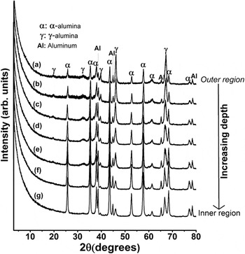
Figure 6 shows the TF-XRD patterns of CMT-Al/Ti alloy after MAO treatment for 60 min with major characteristic peak of α-alumina at 43.3° 2θ and that of γ-alumina at 45.8° 2θ, respectively. The higher intensity peaks of γ-alumina and small intensity peaks of α-alumina revealed γ-alumina as the predominant phase in the outer region of oxide layer as shown in Fig. 6(a). Further, the sequential abrasion and TF-XRD measurements were done on the abraded samples to study the phase evolution of α-alumina and γ-alumina with increasing depth from the outer surface. With increasing depth from outer to inner region of oxide layer, the amount of α-alumina increased and that of γ-alumina decreased gradually as shown by their corresponding peak intensities in TF-XRD patterns of abraded samples in Figs. 6(a)–6(g). It is to be noted that Al peaks are detected since the Al-layer was not fully oxidized since the purpose of this experiment was to study the phase and microstructures formed by MAO of CMT-Al layer while avoiding MAO treatment of reaction layer and underlying Ti alloy substrate. This approach allowed easy handling of the sample during rigorous polishing to remove dense alumina and followed by subsequent TF-XRD measurements.
(a) TF-XRD patterns of CMT-Al/Ti after MAO treatment showing phases of oxide layers with predominant γ-alumina in the outer region; (b–f) with increasing depth from outer regions, the peak intensities of γ-alumina gradually decreased and that of α-alumina gradually increased and (g) TF-XRD pattern of inner regions showing high intensity peaks of α-alumina indicating almost pure α-alumina phase.

E. Hardness measurements by Vickers indentation method
The micro-hardness measurements of the oxide layer were performed by making Vickers indentations across the oxide layer at a distance of 20, 40, and 50 μm from the substrate-coating interface. The oxide layer exhibited a significant variation in micro-hardness with a maximum of ∼1700 HV (average value: 1592 ± 96 HV) around 20 μm from the interface and decreased gradually toward the coating surface to 1400 ± 67 HV and 1300 HV at around 40 and 50 μm from the substrate-coating interface. The dense regions of oxide layer more than 50 μm from the substrate-coating interface were overlapping with outer porous microstructures (data not shown), which made it difficult to interpret the hardness values.
F. Microstructure-phase-hardness correlations in the alumina layer
Structure-phase-property relationships can be discussed using combined microscopic observations, TF-XRD and hardness results. Outer porous region in Fig. 5(a) contains γ-alumina as the predominant phase as shown by TF-XRD of outer regions of oxide layer in Fig. 6(a). Due to porous microstructures and predominant presence of γ-alumina with lower hardness, lower mean Vickers hardness ∼1300 HV was measured in outer regions about 50 μm from the coating-substrate. With increasing depth from the outer regions of oxide layer, gradient microstructural regions were revealed as shown by gradual decrease in size of micro-cracks from ∼0.5–4.2 μm to ∼0.5–1.6 μm within middle regions in Fig. 5(b) to 0.2 μm in innermost regions close to substrate in Fig. 5(c). Similarly, the amount of α-alumina also increased with increasing depth as shown by higher characteristic peak intensity ratios of α-alumina (43.3 2θ)/γ-alumina (45.8 2θ), in Fig. 6. Although, direct comparison between SEM observations and TF-XRD results were not made in this work, some trends in gradients in phase of oxide layer are evident since sequential abrasion and XRD of abraded layers in Figs. 6(a)–6(g) revealed that the amount of γ-alumina decreased and that of α-alumina increased with increasing depth from outer to inner regions of the oxide layer. In a nutshell, with increasing depth from outer to inner regions of oxide layer, amount of α-alumina increases, the spatial distribution and size of micro-cracks decreases, which led to increasing hardness from ∼1300 to 1700 HV in almost pure dense α-alumina regions. In a previous study, phase–hardness relations developed in oxide layers obtained by MAO treatments of Al alloy revealed that increasing amount of α-alumina in the coatings increases the composite hardness of coatings that contain a mixture of γ and α-alumina, Reference Krishna, Gupta and Sundararajan27 which is in agreement with our results. Nonetheless, microstructural details such as the size and distribution of micro-cracks in oxide layer formed by MAO treatments, were not closely observed at high magnifications in these studies, which affect the hardness of pure α-alumina layer significantly, as revealed by microstructure-phase-hardness relations in our previous study. Reference Khanna, Kokubo, Matsushita and Takadama15 In this study, we observed the microstructures of the whole oxide layers containing a mixture of α and γ-alumina and revealed that hardness of oxide layer was increased gradually with a concomitant decrease in size of micro-cracks, which is a new finding. These findings lead to an important conclusion that both the micro-cracks and amount of α-alumina govern the mechanical properties of alumina layers formed by MAO of Al.
It is noteworthy to mention here that in our previous study, the hardness of inner pure α-alumina regions formed by MAO of cold sprayed Al was close to ∼1900 HV as compared to ∼1700 HV measured in this work. It could be because of some porosity in CMT-Al layer which is a characteristic of weld Al layers, Reference Pinto, Pyzalla, Hackl and Bruckner31 as compared to dense Al layer formed by cold spraying of pure Al particles. Reference Khanna, Kokubo, Matsushita, Nomura, Nose, Oomori, Yoshida and Takadama14,Reference Khanna, Kokubo, Matsushita and Takadama15,Reference Khanna, Matsushita, Kokubo and Takadama30 Further improvements of CMT and MAO process parameters are needed to achieve high hardness of α-alumina layer, which is outside the scope of this preliminary investigation.
G. Characterization of reaction layer after MAO treatment
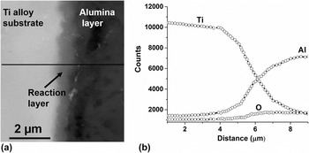
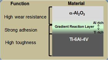
A gradient kind of reaction layer of Al3Ti was formed in situ by deposition of Al on the Ti alloy by CMT method, as shown in Fig. 3. Subsequently, MAO treatment transformed Al to alumina layer. It is required to reveal whether the reaction layer was preserved or not, since it was previously revealed that extensive micro-arc oxidation of reaction layer increased the thickness of reaction layer to 15–20 μm which might have led to large compressive stresses, that resulted in formation of several cracks at the interface between alumina layer and the Ti alloy, indicating poor adhesion. Reference Khanna, Kokubo, Matsushita and Takadama15 Fig. 7(a) shows BSE image of cross-section of the alumina layer/Ti alloy, revealing three regions of dark gray, light gray and the white region corresponding to inner dense region of alumina layer, reaction layer, and the Ti alloy, respectively. The thickness of reaction layer appears to be ∼1.5 μm. Reaction layer was found to be dense and no cracks were observed at Ti-reaction layer or reaction layer-alumina interfaces, suggesting a good adhesion of alumina layer with the Ti alloy. EDS line profile was taken across Ti-reaction layer-alumina region as shown by the line in BSE, Fig. 7(a) and corresponding EDS line profile, Fig. 7(b), which revealed elemental profiles in Ti, Al, and O, wherein, a gradual decrease in Ti and increase in Al across Ti-reaction layer-alumina region close to interface was found. EDS line profiles across these interfaces appear similar to those before MAO treatment. Further compositional analysis performed across Ti-reaction layer-alumina revealed similar gradient compositions of Ti and Al within reaction layer and about 15–18% O was detected within reaction layer, same as before MAO. The presence of oxygen within the reaction layer shows the possibility of some oxides which requires further TEM investigations that are outside the scope of this work. These findings suggest that nascent gradient reaction layer formed by CMT of Al on the Ti alloy was protected from the MAO treatment and remained in-tact with neighboring alumina and Ti alloy surfaces. Overall, a combined CMT and MAO methods reveals a new approach to fabricate a dense and adherent α-alumina layer with gradient reaction layer formed in situ on the surface of the Ti alloy with high toughness for the wear resistance and reliable use of designed alumina/Ti alloy hybrid, as shown schematically in Fig. 8.
(a) BSE image (from left to right) showing Ti alloy, reaction layer and alumina; (b) EDS line profile across these regions showing gradual decrease in Ti and a gradual increase in Al, revealing the gradient compositions of structures containing mainly Al and Ti.

Schematic showing cross-sectional view of newly designed α-Al2O3-Gradient Reaction Layer-Ti–6Al–4V alloy hybrid with their corresponding functions of high wear resistance-strong adhesion-high toughness, respectively.

IV. SUMMARY AND CONCLUSIONS
A new methodology for deposition of dense alumina layer on the Ti alloy hybrid is designed and developed in the light of following findings:
-
(1) A dense layer of Al was deposited onto the Ti alloy by cold metal transfer method in Figs. 1 and 2.
-
(2) SEM/EDS analyses revealed a dense and gradient reaction layer ∼1.5 μm thick at the interface between CMT-Al layer and the Ti alloy in Fig. 3. TF-XRD analyses revealed that reaction layer is mainly composed of Al3Ti in Fig. 4.
-
(3) Combined SEM and XRD analyses revealed that MAO of CMT-Al/Ti formed a graded kind of oxide layer rich in γ-alumina in outer porous region, Fig. 5(a) and with increasing depth, denser microstructural regions with gradients in micro-crack sizes were formed in middle regions in Fig. 5(b) with a concomitant decrease in γ-alumina and increase in α-alumina as revealed by depth wise TF-XRD measurements in Fig. 6. Dense inner pure α-alumina layer in Fig. 6(g) revealed high Vickers hardness ∼1700 HV, similar to sintered alumina.
-
(4) SEM/EDS analyses on cross-section of alumina layer formed on the Ti alloy revealed that a good adhesion between alumina layer and the Ti alloy in Fig. 7 which is attributed to nascent gradient reaction layer at their interface.
In conclusion, dense alumina layer/Ti alloy hybrid with a combination of high hardness (suggesting high wear resistance), good adhesion and reliability were designed and developed in this work which can be potentially used for wear resistant applications. It is noteworthy that Al is known to have cytotoxic effects, however, free Al was detected neither within the alumina layer nor in the reaction layer. Our EDS data showed trace amount of Na, K, and Si in the inner region of oxide layer containing α-alumina. Further tribological and biocompatibility tests of these designed alumina/Ti hybrids should be performed, which are outside the scope of this work.
The research approach proposed in this work is innovative in our opinion, because it represents a new and substantive departure from the status quo by focusing on designing a new kind of ceramic/metal hybrid with high hardness and mechanical reliability by forming a dense layer of α-alumina on Ti–6Al–4V alloy to overcome critical issues such as wear debris formation, material fracture, or inflammation with existing implants. Our preliminary investigation strongly suggest that this approach will be effective in forming an adherent layer of dense α-alumina and is expected to open new horizons in the field of artificial hip joints. The designed ceramic/metal hybrid technology proposed in this work is novel in a broad sense since it can be suitably applied to other medical implants such as knee joint and as a dense ceramic coating on Ti metal for dental implants. It is envisioned that the dense alumina coatings can be applied to Ti alloys that are used as components of aircraft to avoid Ti oxidation issues that have limited their service temperatures to ∼400 °C. Based on the learnings from this work, it is recommended to design gradient reaction layer to improve the mechanical reliability of ceramic coatings on metals.
ACKNOWLEDGMENTS
We would like to acknowledge the funding support from the Japan Society for the Promotion of Science (2412028). Author RK gratefully acknowledge assistance of colleagues from Indian Institute of Technology Madras, for carrying out the deposition of Al coatings on Ti alloys by CMT method and Takuya Yoshida for providing the bipolar power supply facility to conduct MAO experiments.