


1. Introduction
In addition to the continuous progress in the aerospace industry, there has been a growing need to increase the processing quality of aerospace parts. Such parts are typically machined through forging or rolling processes and exhibit the standard characteristics of large and complex monolithic components [Reference Cerutti and Mocellin1]. These characteristics are essential for satisfying the performance specifications of aerospace equipment operating under extreme service conditions. Owing to the inherent advantages, including good payload capacity, high motion dynamics, high accuracy, and space-efficient architectures, machine tools based on parallel mechanisms effectively address the machining requirements of large-scale components [Reference Yang, Baradat, Krut and Pierrot2]. One representative case is the 5-axis machine tool developed by DS-Technologie, which integrates a 3-PRS parallel mechanism (P denotes the prismatic joint, R denotes the revolute joint, and S denotes the spherical joint) as its core architecture [Reference Fan, Zhang, Hu, Shen, Song and Qiu3, Reference Nigatu and Kim4].
The 3-PRS parallel mechanism, characterized by 1T2R (One translation and two rotations) mobility, exemplifies the representative architecture among lower-mobility parallel mechanisms [Reference Liu, Wan, Liu, Chen, Yao and Zhao5]. Carretero et al. [Reference Carretero, Podhorodeski, Nahon and Gosselin6] pioneered the kinematic analysis of this mechanism, establishing fundamental theoretical frameworks for its motion characteristics. The limb architecture has been optimized, resulting in the effective suppression of parasitic motion along the designated axis of the mechanism. Furthermore, investigations, including dynamics [Reference Ma, Tian, Liu and Lu7], static stiffness [Reference Liu, Huang, Chetwynd and Kecskeméthy8], optimization design [Reference Huang, Wang, Wang and Qian9, Reference Lu, Xie, Lyu, Jin, Huang and Ding10], and motion control [Reference Tsai and Yuan11] studies, have been conducted to establish essential theoretical frameworks, leading to significant advances in subsequent studies of parallel mechanisms. The development of the 3-RPS mechanism, a variant of the 3-PRS architecture, can be traced back to Hunt’s research [Reference Hunt12]. The above mechanisms contain no passive limbs and have a symmetric architecture. These parallel mechanisms differ from other typical architectures, such as the Exechon, which features the 1-SPR/2-UPR (U denotes the universal joint) parallel mechanism [Reference López-Custodio, Dai, Fu and Jin13]; the Tricept, which features the 1-UP/3-UPS parallel mechanism [Reference Dong, Liu, Huang and Chetwynd14]; and the Gough–Stewart platform, which features the 6-UPS parallel mechanism [Reference Russo and Dong15]. Typically, the spherical joints of the aforementioned parallel mechanisms are composed of three revolute joints whose axes are mutually perpendicular and intersect at a single point. To meet the critical geometric constraints between the joint axes, it is necessary to employ high-precision components and precise assembly technology to achieve precise spherical joints, thereby increasing the cost of the parallel mechanism. Moreover, considering that the cone angle of the spherical joint in the limb can restrict the orientation capability of parallel mechanisms, scholars have proposed several 1T2R parallel mechanisms that do not require precise spherical joints and have a large orientation workspace, such as the 3-PUU parallel mechanism proposed by Wang et al. [Reference Wang, Xu, Guan and Zhi16] and the 3-UPU parallel mechanism proposed by Song et al. [Reference Song, Zhao, Zhao, Yan and Chen17]. Notably, parallel mechanisms with the same layout of limbs and the same type of joint can present different mobilities. For example, the 3-PUU parallel mechanism studied by Li et al. [Reference Li and Xu18] and the 3-UPU parallel mechanism studied by Di Gregorio et al. [Reference Di Gregorio and Parenti-Castelli19] both have 3T mobility, which differs from the mobility of the mechanisms discussed previously. The reason for the variations in the mobility of the parallel mechanisms lies in the differences in the geometric relationships among the joint axes. Moreover, López-Custodio et al. [Reference López-Custodio, Fu, Dai and Jin20] studied Exechon manipulators with an offset wrist. The offset prevents the revolute axes in the serial module of the Exechon from intersecting, but it does not affect the original mobility of the mechanism. Moreover, such a design avoids the geometric constraints between the axes. Therefore, it is more feasible to develop the mechanism into practice.
In view of this characteristic, the 3-PRRU parallel mechanism studied in this work is a variant of the 3-PRS parallel mechanism with offsets in the spherical joints. The offsets avoid the geometric constraints of the axes of the spherical joint without changing the original 1T2R mobility of the mechanism. However, it is necessary to investigate the effect of the offsets on the kinematic performance of the mechanism. The indices, which are often employed in kinematic performance evaluation and dimensional synthesis of parallel mechanisms, are constructed through Jacobian [Reference Merlet21] or through the use of the concept of a virtual coefficient based on screw theory [Reference Wang, Wu and Liu22]. Thus, one preliminary step is to determine the basis elements of the twist and wrench spaces. [Reference Huang, Wang, Yang, Sun, Chetwynd and Xie23–Reference Huo, Song and Sun26]. Specifically, the identification of the constraints imposed by the limbs on the moving platform and the corresponding restricted motions is necessary for the kinematic analysis of lower-mobility parallel mechanisms. Typically, the identification of the basis elements of the screw systems for a given limb is a relatively straightforward process. Considering PRS, RPS, and SPR kinematic limbs as examples, the elements of each limb constraint system can be determined as a pure force, and the corresponding restricted motion can be identified as a translation [Reference Huang, Yang, Wang, Sun and Chetwynd27], as shown in Figure 1(a), (b), and (c). The limb constraint imposed on the moving platform is always in the direction of the axis for the revolute joint in an arbitrary configuration. The limb constraints of the PU kinematic limb can be identified as two pure forces and one torque [Reference Huang, Yang, Wang, Sun and Chetwynd27]. Moreover, the remaining basis elements can be determined by the inspection method. However, in the limbs where the direction, pitch, and position vector for their basis elements of the twist and wrench spaces are related to both the passive and actuated joint variables, such as in the PRRU limb, determining these basis elements becomes quite complex, as shown in Figure 1(d). To address this issue, this work is focused on the 3-PRRU parallel mechanism. By using screw theory and linear algebra, the procedures for determining the screw systems of the limb are investigated. Specifically, the constraint forms of the limbs vary with the mechanism configuration (involving the interconversion between general screws and line vectors/couples), a characteristic that differs from common parallel mechanisms. Meanwhile, this work reveals the dependence of the basis elements on the mechanism’s configuration. On the basis of this work, the effects of the offsets on the kinematic performance of the parallel mechanism are analyzed by employing force/motion transmissibility indices.
Different types of serial kinematic limbs. (a) PRS limb. (b) RPS limb. (c) SPR limb. (d) PRRU limb.

Figure 1. Long description
A diagram of different types of serial kinematic limbs. Panel A: A PRS limb with a prismatic joint (P-joint), a revolute joint (R-joint), and a spherical joint (S-joint). The constraint is shown in blue. Panel B: An RPS limb with a revolute joint (R-joint), a prismatic joint (P-joint), and a spherical joint (S-joint). The constraint is shown in blue. Panel C: An SPR limb with a spherical joint (S-joint), a prismatic joint (P-joint), and a revolute joint (R-joint). The constraint is shown in blue. Panel D: A PRRU limb with two revolute joints (R-joint), a prismatic joint (P-joint), and a universal joint (U-joint).
The rest of the work is organized as follows. Section 2 first introduces the architecture of the 3-PRRU parallel mechanism with offset joints and then develops a numerical solution for its inverse kinematics based on the geometric constraints existing between the limbs. In Section 3, the specific basis elements of the screw system are determined, and the relationship between the variation in the basis elements and the configuration of the mechanism is revealed. In Section 4, the effects of the offsets on the kinematic performance of the mechanism in both the operation space and the joint space are discussed. Finally, in Section 5, the conclusions are presented.
2. Description and kinematic analysis of the mechanism
2.1. Description of the mechanism
The 3-PRRU parallel mechanism with symmetric architecture that is studied in this work is shown in Figure 2(a). This mechanism is composed of a fixed base, three identical PRRU limbs, and a moving platform. Each limb consists of an actuated prismatic joint connected to the base, followed by two revolute joints perpendicular to each other and a universal joint attached to the moving platform. As shown in Figure 2(b), axis-I denotes the axis of the actuated prismatic joint. Axis-II and axis-III denote the axes of the two revolute joints, respectively. Axis-IV and axis-V denote the axes of the universal joint. Before kinematic analysis, it is necessary to define some key reference points for the 3-PRRU parallel mechanism. These reference points are established based on the topology of the mechanism. Point
 $A_{i}$
(
 $B_{i}$
) is defined as the vertex of the equilateral triangle
 ${\unicode[Arial]{x0394}} A_{1}A_{2}A_{3}$
(
 ${\unicode[Arial]{x0394}} B_{1}B_{2}B_{3}$
), with point
 $O'$
(
 $O$
) being its center point. Point
 $C_{i}$
(
 $P_{i}$
) is the intersection point of axis-III (axis-I) and axis-IV (axis-II). Point
 $Q$
is defined as reference point of the moving platform.
Mechanism with offset joints. (a) 3-PRRU mechanism. (b) Definitions of the key reference points.

2.2. Inverse kinematic analysis of the mechanism
To facilitate the kinematic analysis of the 3-PRRU parallel mechanism, a set of reference frames is established, as shown in Figure 2(b). The goal of the inverse kinematic analysis is to determine the coordinates of the key reference points with respect to the global frame
 ${\mathcal{K}}_{O}$
. The global frame
 ${\mathcal{K}}_{O}$
is defined at the point
 $O$
. The
 $x_{O}$
-axis is parallel to the vector
 $\overset{\longrightarrow }{B_{3}B_{2}}$
, and the
 $z_{O}$
-axis is perpendicular to
 ${\unicode[Arial]{x0394}} B_{1}B_{2}B_{3}$
. A body-fixed frame
 ${\mathcal{K}}_{O'}$
is attached to the moving platform such that its origin is coincident with the point
 $O'$
. The
 $x_{O'}$
-axis is parallel to the vector
 $\overset{\longrightarrow }{A_{3}A_{2}}$
, and the
 $z_{O'}$
-axis is perpendicular to
 ${\unicode[Arial]{x0394}} A_{1}A_{2}A_{3}$
.
The evaluation of the key reference points in the frame
 ${\mathcal{K}}_{O}$
can be expressed as follows
 \begin{equation} \begin{array}{c} \overset{\longrightarrow }{OQ}=\left(\begin{array}{lll} Q_{x} &\quad Q_{y} &\quad Q_{z} \end{array}\right)^{\mathrm{T}},\overset{\longrightarrow }{OA_{i}}=\boldsymbol{R}\left({}^{O'}{\overset{\longrightarrow }{O'A_{i}}}{}-{}^{O'}{\overset{\longrightarrow }{O'Q}}{}\right)+\overset{\longrightarrow }{OQ}\\ \overset{\longrightarrow }{OC_{i}}=\left(\begin{array}{lll} C_{ix} &\quad C_{iy} &\quad C_{iz} \end{array}\right)^{\mathrm{T}},\overset{\longrightarrow }{OP_{i}}=\left(\begin{array}{lll} b\cos \beta _{i} &\quad b\sin \beta _{i} &\quad q_{i} \end{array}\right)^{\mathrm{T}},\overset{\longrightarrow }{OB_{i}}=\left(\begin{array}{lll} b\cos \beta _{i} &\quad b\sin \beta _{i} &\quad 0 \end{array}\right)^{\mathrm{T}} \end{array} \end{equation}
where
 $\overset{\longrightarrow }{OQ}$
(
 $\overset{\longrightarrow }{OA_{i}}$
) denotes the position vector of the point
 $Q$
(
 $A_{i}$
),
 $\boldsymbol{R}$
represented by z-x-z Euler angles
 $(\begin{array}{lll} \psi , & \theta , & \phi \end{array})$
denotes the orientation matrix of the frame
 ${\mathcal{K}}_{O'}$
relative to the frame
 ${\mathcal{K}}_{O} , {}^{O'}{\overset{\longrightarrow }{{O'}A_{i}}}{}=(\begin{array}{lll} a\cos \beta _{i} &\quad a\sin \beta _{i} &\quad 0 \end{array})^{\mathrm{T}}$
and
 ${}^{O'}{\overset{\longrightarrow }{O'Q}}{}=(\begin{array}{lll} 0 &\quad 0 &\quad e \end{array})^{\mathrm{T}}$
denote the position vectors of the point
 $A_{i}$
and the point
 $Q$
, respectively, they are both evaluated in the frame
 ${\mathcal{K}}_{O'} , \beta _{i}=(4\pi i-7\pi )/6$
denotes the limb angle,
 $a$
(
 $e$
) denotes the magnitude of the vector
 $\overset{\longrightarrow }{O'A_{i}}$
(
 $\overset{\longrightarrow }{O'Q}$
),
 $\overset{\longrightarrow }{OC_{i}}$
(
 $\overset{\longrightarrow }{OP_{i}}$
) denotes the position vector of the point
 $C_{i}$
(
 $P_{i}$
),
 $b$
(
 $q_{i}$
) denotes the magnitude of the vector
 $\overset{\longrightarrow }{OB_{i}}$
(
 $\overset{\longrightarrow }{B_{i}P_{i}}$
), and
 $\overset{\longrightarrow }{OB_{i}}$
denotes the position vector of the point
 $B_{i} , i=1,2,3$
.
Note that the geometric relationships between the limbs can serve as constraints for position analysis. These constraints can be categorized into dimensional constraints and orthogonality constraints. Specifically, the dimensional constraints can be expressed as follows
 \begin{equation}\big(\overset{\longrightarrow} {P_{i}C_{i}}\big)^{T}\overset{\longrightarrow} {P_{i}C_{i}}-{l}_{1}^{2}=0,\big(\overset{\longrightarrow} {C_{i}A_{i}}\big)^{T}\overset{\longrightarrow} {C_{i}A_{i}}-{l}_{2}^{2}=0\end{equation}
where
 $l_{1}$
and
 $l_{2}$
denote the magnitude of the vector
 $\overset{\longrightarrow }{P_{i}C_{i}}$
and the vector
 $\overset{\longrightarrow }{C_{i}A_{i}}$
, respectively.
Moreover, the orthogonality constraints can be expressed as follows
 \begin{align}\big(\overset{\longrightarrow} {C_{i}A_{i}}\big)^{T}\overset{\longrightarrow} {A_{m}A_{n}}=0, \big(\overset{\longrightarrow} {P_{i}C_{i}}\big)^{T}\overset{\longrightarrow} {B_{m}B_{n}}&=0\\ \nonumber \big(\big(\overset{\longrightarrow} {P_{i}C_{i}}\big)\times \big(\overset{\longrightarrow} {C_{i}A_{i}}\big)\big)^{T}\overset{\longrightarrow} {B_{m}B_{n}}&=0\end{align}
where
 $m=1,2,3 , n=1,2,3$
and
 $i\neq m\neq n$
.
Hence, 15 equations with 18 variables are derived from Eqs. (2) and (3). Fifteen of the variables are unknowns, and the remaining variables are known. These variables that are related to the mechanism include the Euler angle (
 $\psi , \theta , \phi$
) of the moving platform, the elements (
 $Q_{x} , Q_{y} , Q_{z}$
) of the position vector
 $\overset{\longrightarrow }{OQ}$
, the elements (
 $C_{ix} , C_{iy} , C_{iz}$
) of the position vector
 $\overset{\longrightarrow }{OC_{i}}$
, and the actuated joint variables
 $q_{i}$
. The inverse position analyses are performed numerically in this paper, in a similar way to what happens with the Exechon manipulators with an offset wrist [Reference López-Custodio, Fu, Dai and Jin20]. For the inverse position analyses, the following information is known:
 $\psi$
and
 $\theta$
of the tool vector
 $\boldsymbol{r}_{Tool}=(\begin{array}{lll} \sin \psi\! \sin \theta & -\cos \psi\! \sin \theta & \cos \theta \end{array})^{\mathrm{T}}$
, as well as
 $Q_{z}$
, which representing the position of the tip of the tool along the
 $z_{O}$
-axis with respect to the frame
 ${\mathcal{K}}_{O}$
. Moreover, the aforementioned equations are solved using the classical Newton iterative method, a standard approach in this field [Reference Wang, Xu, Guan and Zhi16], with the solution process implemented in software. Consequently, all the coordinates of the key reference points for the parallel mechanism in an arbitrary configuration can be solved. Moreover, a numerical case study on the inverse kinematics of the 3-PRRU parallel mechanism is provided in Appendix A.
3. Twist and wrench spaces and their bases
For the force/motion transmissibility analysis, the basis elements of the twist and wrench spaces of the PRRU limb must be obtained. Therefore, in this section, the basis elements are determined, and the relationships between the variations in these elements and the configurations of the parallel mechanism are revealed.
The unit twist (the unit wrench) is represented by Plücker axial coordinates (Plücker ray coordinates). All the screws are evaluated in the frame
 ${\mathcal{K}}_{Q'}$
, with its origin temporarily being coincident with the reference point
 $Q$
and its three orthogonal axes being parallel to the frame
 ${\mathcal{K}}_{O}$
, as shown in Figure 3.
Schematic diagram of the 3-PRRU mechanism.

In accordance with screw theory and linear algebra, when the inaccessible motions are considered, the realistic instantaneous motions of a
 $f-\mathrm{DOF}$
kinematic limb can be defined as a 6-dimensional vector space
 $\mathscr{T}_{i}$
[Reference Huang, Wang, Yang, Sun, Chetwynd and Xie23]. Moreover, the external wrenches imposed on the output link are equilibrated both by forces/couples from actuated joints and by constraints from mechanical structures, which span a 6-dimensional vector space
 $\mathscr{W}_{i}$
[Reference Huang, Liu and Chetwynd28]. Thus, the twist space
 $\mathscr{T}_{i}$
and wrench space
 $\mathscr{W}_{i}$
can be expressed as follows
 \begin{equation} \mathscr{T}_{i}=\mathscr{T}_{a,i}\oplus \mathscr{T}_{c,i},\mathscr{W}_{i}=\mathscr{W}_{a,i}\oplus \mathscr{W}_{c,i} \end{equation}
where
 \begin{align*} \begin{array}{c} \mathscr{T}_{a,i}=\text{span}\left\{\begin{array}{lllll} \hat{\mathbf{\$}}_{ta,1,i} & \cdots & \hat{\mathbf{\$}}_{ta,j,i} & \cdots & \hat{\mathbf{\$}}_{ta,f,i} \end{array}\right\},\mathscr{T}_{c,i}=\text{span}\left\{\begin{array}{lllll} \hat{\mathbf{\$}}_{tc,1,i} & \cdots & \hat{\mathbf{\$}}_{tc,k,i} & \cdots & \hat{\mathbf{\$}}_{tc,6-f,i} \end{array}\right\}\\[8pt] \mathscr{W}_{a,i}=\text{span}\left\{\begin{array}{lllll} \hat{\mathbf{\$}}_{wa,1,i} & \cdots & \hat{\mathbf{\$}}_{wa,j,i} & \cdots & \hat{\mathbf{\$}}_{wa,f,i} \end{array}\right\},\mathscr{W}_{c,i}=\text{span}\left\{\begin{array}{lllll} \hat{\mathbf{\$}}_{wc,1,i} & \cdots & \hat{\mathbf{\$}}_{wc,k,i} & \cdots & \hat{\mathbf{\$}}_{wc,6-f,i} \end{array}\right\} \end{array} \end{align*}
 $\mathscr{T}_{a,i}$
(
 $\mathscr{T}_{c,i}$
) denotes the twist subspace of permissions (restrictions), with
 $\hat{\mathbf{\$}}_{ta,j,i}$
(
 $\hat{\mathbf{\$}}_{tc,k,i}$
) being the elements of it,
 $\mathscr{W}_{a,i}$
(
 $\mathscr{W}_{c,i}$
) denotes the wrench subspace of actuations (constraints), with
 $\hat{\mathbf{\$}}_{wa,j,i}$
(
 $\hat{\mathbf{\$}}_{wc,k,i}$
) being the elements of it, and
 $\oplus$
denotes the direct sum. The relationships of these subspaces are used to determine the basis elements of the four subspaces, and the process for obtaining the elements is presented as follows.
The basis elements of
 $\mathscr{T}_{a,i} , \mathscr{W}_{c,i} , \mathscr{T}_{c,i}$
and
 $\mathscr{W}_{a,i}$
are determined sequentially. Specifically, the basis elements of the subspace
 $\mathscr{T}_{a,i}$
can be uniquely determined according to the types of all the 1-DOF joints in the PRRU limb. These elements can be expressed as follows
 \begin{equation} \begin{array}{c} \hat{\mathbf{\$}}_{ta,1,i}\mathbf{=}\left(\begin{array}{c} \boldsymbol{s}_{1,i}\\ \mathbf{0} \end{array}\right)\!,\hat{\mathbf{\$}}_{ta,2,i}\mathbf{=}\left(\begin{array}{c} \left(\boldsymbol{d}_{i}-l_{2}\boldsymbol{s}_{4,i}-l_{1}\boldsymbol{c}_{i}\right)\times \boldsymbol{s}_{2,i}\\ \boldsymbol{s}_{2,i} \end{array}\right)\\[12pt] \hat{\mathbf{\$}}_{ta,3,i}\mathbf{=}\left(\begin{array}{c} \left(\boldsymbol{d}_{i}-l_{2}\boldsymbol{s}_{4,i}\right)\times \boldsymbol{s}_{3,i}\\ \boldsymbol{s}_{3,i} \end{array}\right),\hat{\mathbf{\$}}_{ta,4,i}\mathbf{=}\left(\begin{array}{c} \boldsymbol{d}_{i}\times \boldsymbol{s}_{4,i}\\ \boldsymbol{s}_{4,i} \end{array}\right),\hat{\mathbf{\$}}_{ta,5,i}\mathbf{=}\left(\begin{array}{c} \boldsymbol{d}_{i}\times \boldsymbol{s}_{5,i}\\ \boldsymbol{s}_{5,i} \end{array}\right) \end{array} \end{equation}
where
 $\boldsymbol{d}_{i}=\boldsymbol{a}_{i}-\boldsymbol{e}_{i}$
. Without loss of generality,
 $\boldsymbol{s}_{j,i}$
denotes the unit vector along the j-th 1-DOF joint axis of limb i.
 $\boldsymbol{c}_{i}$
denotes the unit vector parallel to the vector
 $\overset{\longrightarrow }{P_{i}C_{i}}$
. These unit vectors can be obtained by normalizing the position vectors between the corresponding key reference points of the mechanism. Notably,
 $\boldsymbol{s}_{3,i}$
can be represented by
 $\boldsymbol{s}_{3,i}=\boldsymbol{c}_{i}\times \boldsymbol{s}_{2,i}$
.
To obtain the constraints imposed by the PRRU limbs on the moving platform, a set of body-fixed frames should be determined, as shown in Figure 3. A body-fixed frame
 ${\mathcal{K}}_{1,i}$
(
 ${\mathcal{K}}_{2,i}$
) is attached to the prismatic joint (the revolute joint), with its origin being coincident with the key reference point
 $P_{i}$
. The
 $x_{1,i}$
-axis (
 $x_{2,i}$
-axis) is parallel to the unit vector
 $\boldsymbol{s}_{2,i}$
, and the
 $z_{1,i}$
-axis (
 $z_{2,i}$
-axis) is parallel to the unit vector
 $\boldsymbol{s}_{1,i}$
(
 $\boldsymbol{c}_{i}$
). A body-fixed frame
 ${\mathcal{K}}_{3,i}$
is attached to another revolute joint whose origin is coincident with the key reference point
 $C_{i}$
, with its
 $y_{3,i}$
-axis being parallel to the unit vector
 $\boldsymbol{s}_{3,i}$
and its
 $z_{3,i}$
-axis being parallel to the unit vector
 $\boldsymbol{s}_{4,i}$
.
 ${\mathcal{K}}_{4,i}$
and
 ${\mathcal{K}}_{5,i}$
denote two body-fixed frames whose origins are coincident with the key reference point
 $A_{i}$
. These frames are attached to the universal joint such that the
 $z_{4,i}$
-axis and
 $x_{5,i}$
-axis are in the directions of the unit vector
 $\boldsymbol{s}_{4,i}$
and the unit vector
 $\boldsymbol{s}_{5,i}$
, respectively. Moreover, the
 $x_{4,i}$
-axis and
 $z_{5,i}$
-axis are in the directions of the unit vector
 $\boldsymbol{s}_{5,i}$
and the vector
 $\boldsymbol{e}$
, respectively.
In accordance with the properties of the four subspaces,
 $\mathscr{T}_{a,i}$
and
 $\mathscr{W}_{c,i}$
are orthogonal complements of each other; i.e.,
 $\mathscr{W}_{c,i}={\mathrm{T}}_{a,i}^{\bot }$
. Thus, a set of equations can be obtained from
 ${\hat{\mathbf{\$}}}_{wc,1,i}^{\mathrm{T}}\hat{\mathbf{\$}}_{ta,j,i}=0,1\leq j\leq f$
. When
 $f=5 , \hat{\mathbf{\$}}_{wc,1,i}$
can be determined uniquely by solving the null space of the following homogeneous algebraic equations. Notably, the elements of the unit twists derived from Eq. (5) are numerical solutions only. Hence, it is better to first express them in the frame
 ${\mathcal{K}}_{3,i}$
and then transform them into the frame
 ${\mathcal{K}}_{Q'}$
. Thus, the equations can be expressed as follows
 \begin{equation} {}^{3,i}{\boldsymbol{J}}{_{ta,i}^{}}{}^{3,i}{\hat{\mathbf{\$}}}{_{wc,1,i}^{}}=\mathbf{0} \end{equation}
where
 \begin{equation*} {}^{3,i}{\boldsymbol{J}}{_{ta,i}^{}}=\left[\begin{array}{c@{\quad}c@{\quad}c@{\quad}c@{\quad}c@{\quad}c} -\cos \theta _{1,i}\sin \theta _{2,i} & \sin \theta _{1,i} & \cos \theta _{1,i}\cos \theta _{2,i} & 0 & 0 & 0\\ 0 & -l_{1} & 0 & \cos \theta _{2,i} & 0 & \sin \theta _{2,i}\\ 0 & 0 & 0 & 0 & 1 & 0\\ 0 & 0 & 0 & 0 & 0 & 1\\ -l_{2}\sin \theta _{3,i} & l_{2}\cos \theta _{3,i} & 0 & \cos \theta _{3,i} & \sin \theta _{3,i} & 0 \end{array}\right] \end{equation*}
 $\theta _{n,i},1\leq n\leq 4$
denotes the rotation angle of frame
 ${\mathcal{K}}_{n+1,i}$
relative to frame
 ${\mathcal{K}}_{n,i}$
, which can be obtained from the orientation matrix between the corresponding body-fixed frames.
The transformation formula of the unit wrench can be expressed as follows
 \begin{equation} \hat{\mathbf{\$}}_{wc,1,i}={}^{Q'}{\left[\mathrm{Ad}_{T}\right]}{_{3,i}^{-\mathrm{T}}}{}^{3,i}{\hat{\mathbf{\$}}}{_{wc,1,i}^{}} \end{equation}
where
 \begin{equation*} {}^{Q'}{\left[\mathrm{Ad}_{T}\right]}{_{3,i}^{}}=\left[\begin{array}{c@{\quad}c} {}^{Q'}{\boldsymbol{R}}{_{3,i}^{}} & \left[{}^{Q'}{\boldsymbol{p}}{_{3,i}^{}}\times \right]{}^{Q'}{\boldsymbol{R}}{_{3,i}^{}}\\[5pt] \mathbf{0} & {}^{Q'}{\boldsymbol{R}}{_{3,i}^{}} \end{array}\right],{}^{Q'}{\boldsymbol{p}}{_{3,i}^{}}=-\left(l_{2}\boldsymbol{s}_{4,i}-\boldsymbol{a}_{i}+\boldsymbol{e}\right) \end{equation*}
 ${}^{Q'}{\boldsymbol{R}}{_{3,i}^{}}\in \mathrm{SO}(3)$
denotes the orientation matrix of the frame
 ${\mathcal{K}}_{3,i}$
relative to the frame
 ${\mathcal{K}}_{Q'}$
. Consequently, the numerical solution of the unit wrench of constraints can be obtained. However, this solution cannot meet the requirements of subsequent analyses. According to screw theory, three key elements of a unit screw are position, direction, and pitch. On the basis of the coaxial superposition principle,
 $\hat{\mathbf{\$}}_{wc,1,i}$
can be written as follows
 \begin{equation} \hat{\mathbf{\$}}_{wc,1,i}={\hat{\mathbf{\$}}}_{wc,1,i}^{m}+h_{wc,1,i}{\hat{\mathbf{\$}}}_{wc,1,i}^{m'}=\left(\begin{array}{c} \boldsymbol{s}_{wc,1,i}\\ \boldsymbol{r}_{wc,1,i}\times \boldsymbol{s}_{wc,1,i} \end{array}\right)+h_{wc,1,i}\left(\begin{array}{c} \mathbf{0}\\ \boldsymbol{s}_{wc,1,i} \end{array}\right) \end{equation}
where
 ${\hat{\mathbf{\$}}}_{wc,1,i}^{m}$
(
 ${\hat{\mathbf{\$}}}_{wc,1,i}^{m'}$
) denotes a pure force (a torque) in the form of a unit line vector (a unit couple),
 $\boldsymbol{s}_{wc,1,i}$
denotes a unit vector representing the direction,
 $\boldsymbol{r}_{wc,1,i}$
denotes the position vector of an arbitrary point on the screw axis in the frame
 ${\mathcal{K}}_{Q'}$
, and
 $h_{wc,1,i}$
denotes the magnitude of the pitch.
Hence, it is necessary to solve
 $\boldsymbol{r}_{wc,1,i}$
and
 $h_{wc,1,i}$
, respectively. Considering the randomness of the position vectors, an orthogonal geometric constraint is introduced, i.e.,
 $\boldsymbol{r}_{wc,1,i}\bot \boldsymbol{s}_{wc,1,i}$
. Thus,
 $\boldsymbol{r}_{wc,1,i}$
and
 $h_{wc,1,i}$
can be obtained as follows
 \begin{equation} \boldsymbol{r}_{wc,1,i}=\boldsymbol{t}\times \boldsymbol{t}_{0},h_{wc,1,i}=\boldsymbol{t}^{\mathrm{T}}\boldsymbol{t}_{0},\hat{\mathbf{\$}}_{wc,1,i}=\left(\begin{array}{ll} \boldsymbol{t}^{\mathrm{T}} & {\boldsymbol{t}}_{0}^{\mathrm{T}} \end{array}\right)^{\mathrm{T}} \end{equation}
where
 $\hat{\mathbf{\$}}_{wc,1,i}$
denotes the unit wrench with respect to the frame
 ${\mathcal{K}}_{Q'}$
containing
 $\boldsymbol{r}_{wc,1,i}$
and
 $h_{wc,1,i}$
. Consequently, all the information associated with
 $\hat{\mathbf{\$}}_{wc,1,i}$
is obtained.
Furthermore, in accordance with the physical meaning of reciprocal screws,
 $\hat{\mathbf{\$}}_{tc,1,i}$
represents the constrained mobility when
 ${\hat{\mathbf{\$}}}_{wc,1,i}^{\mathrm{T}}\hat{\mathbf{\$}}_{tc,1,i}\neq 0$
is satisfied. Considering that
 $\hat{\mathbf{\$}}_{tc,1,i}$
is not unique, the strategy employed in this work is to obtain its closed-form solutions while minimizing the number of unknowns in
 $\hat{\mathbf{\$}}_{tc,1,i}$
. Moreover, given that an arbitrary motion of a rigid body can be defined as screw motion,
 $\hat{\mathbf{\$}}_{tc,1,i}$
is defined as follows
 \begin{equation} \hat{\mathbf{\$}}_{tc,1,i}={\hat{\mathbf{\$}}}_{tc,1,i}^{m}+h_{tc,1,i}{\hat{\mathbf{\$}}}_{tc,1,i}^{m'}=\left(\begin{array}{c} \boldsymbol{r}_{tc,1,i}\times \boldsymbol{s}_{tc,1,i}\\ \boldsymbol{s}_{tc,1,i} \end{array}\right)+h_{tc,1,i}\left(\begin{array}{c} \boldsymbol{s}_{tc,1,i}\\ \mathbf{0} \end{array}\right) \end{equation}
where
 ${\hat{\mathbf{\$}}}_{tc,1,i}^{m}$
(
 ${\hat{\mathbf{\$}}}_{tc,1,i}^{m'}$
) denotes the rotational mobility (translational mobility) in the form of a unit line vector (a unit couple),
 $\boldsymbol{s}_{tc,1,i}$
denotes a unit vector representing the direction,
 $\boldsymbol{r}_{tc,1,i}$
denotes the position vector of an arbitrary point on the screw axis in the frame
 ${\mathcal{K}}_{Q'}$
, and
 $h_{tc,1,i}$
denotes the magnitude of the pitch. Let
 $\boldsymbol{r}_{tc,1,i}=\boldsymbol{r}_{wc,1,i}$
and
 $\boldsymbol{s}_{tc,1,i}=\boldsymbol{s}_{wc,1,i}$
. Physically,
 ${\hat{\mathbf{\$}}}_{tc,1,i}^{m}$
denotes the rotational mobility constrained by
 ${\hat{\mathbf{\$}}}_{wc,1,i}^{m'}$
, and
 ${\hat{\mathbf{\$}}}_{tc,1,i}^{m'}$
denotes the translational mobility constrained by
 ${\hat{\mathbf{\$}}}_{wc,1,i}^{m}$
.
Considering that
 $\mathscr{W}_{a,i}$
is the dual of
 $\mathscr{T}_{a,i}$
, i.e.,
 $\mathscr{W}_{a,i}={\mathrm{T}}_{a,i}^{*}$
, the transmission wrench screw
 $\hat{\mathbf{\$}}_{wa,1,i}$
of each limb can be determined. Thus,
 $\hat{\mathbf{\$}}_{wa,1,i}$
can be written as follows
 \begin{equation} \hat{\mathbf{\$}}_{wa,1,i}=\left(\begin{array}{c} \boldsymbol{s}_{4,i}\\ \boldsymbol{d}_{i}\times \boldsymbol{s}_{4,i} \end{array}\right) \end{equation}
Moreover,
 $\mathscr{W}_{a,i}$
and
 $\mathscr{T}_{c,i}$
satisfy
 $\mathscr{W}_{a,i}={\mathrm{T}}_{c,i}^{\bot }$
. Thus, the closed-form solution of
 $h_{tc,1,i}$
can be obtained as follows
 \begin{equation} h_{tc,1,i}=-\frac{\left(\boldsymbol{r}_{wc,1,i}\times \boldsymbol{s}_{wc,1,i}\right)^{\mathrm{T}}\boldsymbol{s}_{4,i}+\left(\boldsymbol{d}_{i}\times \boldsymbol{s}_{4,i}\right)^{\mathrm{T}}\boldsymbol{s}_{wc,1,i}}{{\boldsymbol{s}}_{4,i}^{\mathrm{T}}\boldsymbol{s}_{wc,1,i}} \end{equation}
However, when
 $h_{wc,1,i}\rightarrow 0 , \hat{\mathbf{\$}}_{wc,1,i}$
degenerates from a general screw to a line vector (pure force), rendering Eq. (12) indeterminate in the form of “
 $0/0$
.” To avoid this issue, when
 $h_{wc,1,i}\rightarrow 0$
, let
 $h_{tc,1,i}\rightarrow \infty$
. Physically, if the type of the basis element of
 $\mathscr{W}_{c,i}$
is a pure force, the corresponding constrained motion is a translation. Other cases are explained in the following sections. Moreover, given the properties of
 $\mathscr{W}_{a,i}={\mathscr{T}}_{c,i}^{\bot }$
and
 $\mathscr{W}_{a,i}={\mathscr{T}}_{a,i}^{*}$
, the other specific basis elements of
 $\mathscr{W}_{a,i}$
can be determined as follows
 \begin{equation} \boldsymbol{W}^{\mathrm{T}}\mathbf{\$ }_{wa,l,i}=\boldsymbol{\delta }_{l},l=2,\cdots ,f \end{equation}
where
 $\boldsymbol{W}=[\begin{array}{llllllll} \hat{\mathbf{\$}}_{ta,1,i} & \cdots & \hat{\mathbf{\$}}_{ta,j,i} & \cdots & \hat{\mathbf{\$}}_{ta,f,i} & \hat{\mathbf{\$}}_{tc,1,i} & \cdots & \hat{\mathbf{\$}}_{tc,6-f,i} \end{array}] , \boldsymbol{\delta }_{l}=(\begin{array}{lllll} 0 & 1_{(l=j)} & 0 & \cdots & 0 \end{array})^{\mathrm{T}}$
, and
 $\hat{\mathbf{\$}}_{wa,j,i},l=j$
can be obtained by normalizing
 $\mathbf{\$ }_{wa,l,i}$
.
Consequently, the basis elements of the four subspaces are obtained. The results will be employed in the analysis of the force/motion transmissibility of the mechanism. However, the basis elements for both the wrench subspace of constraints and the twist subspace of restrictions, which are required to construct the force/motion transmissibility indices, are not uniquely defined across different configurations of the mechanism. To further analyze the relationships among them, a set of dimensional parameters of the 3-PRRU parallel mechanism is given:
 $a=77\,\mathrm{mm} , b=210\,\mathrm{mm} , l_{1}=200\,\mathrm{mm} , l_{2}=118\,\mathrm{mm}$
, and
 $e=55\,\mathrm{mm}$
. In accordance with the kinematic analysis presented in Section 2, the variations in the basis elements within the workspace
 $W_{Qt}$
satisfying
 $r_{Qz}=400\,\mathrm{mm} , \psi \in [0^{\circ },360^{\circ }]$
and
 $\theta \in [0^{\circ },45^{\circ }]$
are analyzed (without singularity). The workspace
 $W_{Qt}$
is shown in Figure 4.
Workspace of the 3-PRRU parallel mechanism.

Figure 4. Long description
A diagram of a 3-PRRU parallel mechanism. The diagram includes a spherical workspace labeled W_Qtl, with a central region labeled Q. Three planes, labeled Πc1, Πc2, and Πc3, intersect within the workspace. The mechanism consists of multiple joints and links, including prismatic, revolute, and spherical joints. The links are connected in a specific configuration to form the parallel mechanism.
Considering that the pitch indicates whether a nonzero screw takes the form of a line vector, a couple or a general screw, the variations in the pitches of
 $\hat{\mathbf{\$}}_{wc,1,1}$
and
 $\hat{\mathbf{\$}}_{tc,1,1}$
for limb 1 within the given workspace are taken as an example, as shown in Figure 5. When
 $Q\notin {\prod}_{1}^{c}$
, the unit wrench of constraints and the unit twist of restrictions can both be identified as general screws with
 $| h_{wc,1,1}| =| h_{tc,1,1}| \neq 0$
.
 ${\prod}_{i}^{c}$
denotes a plane within the workspace that is geometrically coincident with the plane determined by the key reference points
 $O , B_{i}$
and
 $P_{i}$
. According to the physical meaning of reciprocal screws,
 $\hat{\mathbf{\$}}_{tc,1,1}$
can represent the constrained mobility only when
 $h_{wc,1,1}=h_{tc,1,1}$
is satisfied. Moreover, combined with Eq. (10), when the wrench of constraints imposed by the limbs on the moving platform is a general screw, its corresponding constrained mobility can be represented as a general screw that is coaxial and collinear with the same pitch. Moreover, the wrench of constraints degenerates into a line vector (a pure force), and the twist of restrictions are reduced from screws to couples (translation) when the reference point
 $Q\in {\prod}_{1}^{c}$
with
 $| h_{wc,1,1}| \rightarrow 0$
and
 $| h_{tc,1,1}| \rightarrow \infty$
.
Distribution of the pitches. (a) Distribution of
 $| h_{wc,1,1}|$
. (b) Distribution of
 $| h_{tc,1,1}|$
.

In addition, the relationships between the basis elements and the configurations of the mechanism can be further revealed through visualization, as shown in Figure 6. Notably, when
 $\theta _{2,i}=0^{^{\circ}}(i=1,2,3)$
, the basis elements of the wrench subspaces of constraints and the basis elements of the twist subspaces of restrictions can be defined as screws in the form of line vectors and couples, respectively, which are all along the direction of the unit vector
 $\boldsymbol{s}_{2,i}$
. Moreover, the axes of the unit wrenches of constraints pass through the key reference point
 $C_{i}$
, as shown in Figures 6(a) and (c). Furthermore, when
 $\theta _{2,i}\neq 0^{^{\circ}}$
, the aforementioned basis elements are both general screws, and their axes exhibit positional variability around the key reference point
 $C_{i}$
. Moreover, their axes are no longer parallel to unit vector
 $\boldsymbol{s}_{2,i}$
, and they are all in planes parallel to
 ${\unicode[Arial]{x0394}} B_{1}B_{2}B_{3}$
, as shown in Figures 6(b) and (d).
Screw visualization. (a)
 $\psi =0^{\circ },\theta =0^{\circ }$
. (b)
 $\psi =60^{\circ },\theta =20^{\circ }$
. (c)
 $\psi =180^{\circ },\theta =20^{\circ }$
. (d)
 $\psi =300^{\circ },\theta =20^{\circ }$
.

Figure 6. Long description
Panel A: A diagram of the 3-PRS parallel mechanism showing line vectors and a couple. The mechanism includes points labeled B1, B2, B3, C1, P1, and O. Line vectors are represented by black, blue, and red arrows labeled as s_wa,1,1, s_ta,2,1, s_wc,1,1, and s_tc,1,1. A couple is represented by a red arrow labeled s_tc,1,1. Panel B: A diagram of the 3-PRS parallel mechanism showing line vectors and a screw. The mechanism includes points labeled B1, B2, B3, C1, P1, and O. Line vectors are represented by black, blue, and red arrows labeled as s_wa,1,1, s_ta,2,1, s_wc,1,1, and s_tc,1,1. A screw is represented by a red arrow labeled s_wc,1,1. Panel C: A diagram of the 3-PRS parallel mechanism showing line vectors and a screw. The mechanism includes points labeled B1, B2, B3, C1, P1, and O. Line vectors are represented by black, blue, and red arrows labeled as s_wa,1,1, s_ta,2,1, s_wc,1,1, and s_tc,1,1. A screw is represented by a red arrow labeled s_tc,1,1. Panel D: A diagram of the 3-PRS parallel mechanism showing line vectors and a screw. The mechanism includes points labeled B1, B2, B3, C1, P1, and O. Line vectors are represented by black, blue, and red arrows labeled as s_wa,1,1, s_ta,2,1, s_wc,1,1, and s_tc,1,1. A screw is represented by a red arrow labeled s_tc,1,1.
4. Force/motion transmissibility analysis
The force transmissibility characterizes the capacity of each limb within the parallel mechanisms to balance the external forces imposed on the moving platform through the transmission wrench screws and constraint wrench screws. Moreover, the motion transmissibility characterizes the capacity of the motion provided by the actuated joints in the limbs to be transmitted to the movement of the moving platform. Therefore, analyzing the effect of the offsets in the joints on the mechanism’s force/motion transmissibility is crucial. In accordance with the concept of the virtual coefficient [Reference Wang, Wu and Liu22, Reference Liu, Wang, Huang, Chetwynd and Kecskeméthy29], the following dimensionless local indices can be defined for the lower-mobility, nonredundant 3-PRRU parallel mechanism
 \begin{equation} \eta _{sp}=\min _{i=1\sim 3}\left\{\frac{\left| {\hat{\mathbf{\$}}}_{wa,1,i}^{\mathrm{T}}\hat{\mathbf{\$}}_{ta,1,i}\right| }{\left| {\hat{\mathbf{\$}}}_{wa,1,i}^{\mathrm{T}}\hat{\mathbf{\$}}_{ta,1,i}\right| _{\max }}\right\},\eta _{pp}=\min _{i=1\sim 3}\left\{\frac{\left| {\hat{\mathbf{\$}}}_{wa,1,i}^{\mathrm{T}}{\hat{\mathbf{\$}}}_{ta,1,i}^{\ast }\right| }{\left| {\hat{\mathbf{\$}}}_{wa,1,i}^{\mathrm{T}}{\hat{\mathbf{\$}}}_{ta,1,i}^{\ast }\right| _{\max }}\right\},\eta _{pr}=\min _{i=1\sim 3}\left\{\frac{\left| {\hat{\mathbf{\$}}}_{wc,1,i}^{\mathrm{T}}{\hat{\mathbf{\$}}}_{tc,1,i}^{\ast }\right| }{\left| {\hat{\mathbf{\$}}}_{wc,1,i}^{\mathrm{T}}{\hat{\mathbf{\$}}}_{tc,1,i}^{\ast }\right| _{\max }}\right\} \end{equation}
where
 $\eta _{sp}$
(
 $\eta _{pp}$
) denotes the input transmission index (the output transmission index),
 $\eta _{pr}$
denotes the output constraint index,
 ${\hat{\mathbf{\$}}}_{ta,1,i}^{\ast }$
(
 ${\hat{\mathbf{\$}}}_{tc,1,i}^{\ast }$
) denotes the output twist screw (the virtual output twist screw),
 $\hat{\mathbf{\$}}_{ta,1,i}$
denotes the input twist screw in the limb
 $i$
, and
 ${\hat{\mathbf{\$}}}_{ta,1,i}^{\ast }$
(
 ${\hat{\mathbf{\$}}}_{tc,1,i}^{\ast }$
) denotes an element that can be determined by the contradictory relationship between the mobility and constraint [Reference Song, Zhao, Zhao, Yan and Chen17, Reference Chen, Liu, Xie and Sun30] in the lower-mobility 3-PRRU parallel mechanism.
4.1. Singularity analysis
It is widely recognized that parallel mechanisms experience a change in their number of DOFs at singular configurations. This phenomenon has a detrimental effect on kinematic performance, rendering the mechanism unstable. Consequently, identifying singularities is critical in the force/motion transmissibility analysis of parallel mechanisms.
According to the input transmission index
 $\eta _{sp} , \eta _{sp}\rightarrow 0$
when
 $\boldsymbol{s}_{1,i}\bot\, \boldsymbol{s}_{4,i}$
, causing the occurrence of serial singularities as shown in Figure 7. It means that the motion from the actuated joint in each limb fails to be transmitted through its corresponding transmission wrench screw.
Specific serial singularity configurations of 3-PRRU parallel mechanism.

Distribution of
 $\eta _{o}$
for 3-PRRU parallel mechanism.

Moreover, when
 $\eta _{pp}\rightarrow 0$
or
 $\eta _{pr}\rightarrow 0$
, the parallel singularity occurs. It means that the force from each limb fails to be transmitted to the moving platform. Considering that the parallel singularity of the 3-PRRU parallel mechanism depends on its dimensional parameters, the identification of such singularities in the mechanism can be efficiently performed via an exhaustive search over the possible configurations. Thus, an index
 $\eta _{o}=\min (\eta _{pp},\eta _{pr})$
is defined to quantify the distance from a given configuration to parallel singularities. The detailed proof has been presented in Ref. [Reference Liu, Wu and Wang31] and is therefore omitted here. Figure 8 shows a case study of the index
 $\eta _{o}$
for the 3-PRRU parallel mechanism (
 $l_{1}=260\,\mathrm{mm} , l_{2}=110\,\mathrm{mm}$
) and demonstrates that the parallel singularities are located at the boundary of the orientation workspace.
4.2. Transmissibility analysis
Considering the consistency of the performance of the mechanism along the
 $z_{O}\,$
-axis, the force/motion transmissibility is analyzed only in the orientation workspace. Moreover, within the orientation workspace
 $S$
(
 $\psi \in [0^{\circ },360^{\circ }]$
and
 $\theta \in [0^{\circ },45^{\circ }]$
), two global transmission indices are defined by integrating the mean value and the standard deviation of the local indices
 \begin{equation} \eta _{avg}=\frac{\int _{S}\eta\, \mathrm{d}S}{S},\eta _{std}=\sqrt{\frac{\int _{S}\left(\eta -\eta _{avg}\right)^{2}\mathrm{d}S}{S}} \end{equation}
Hence, on the basis of the previous work in this study, the distributions of the local force/motion transmissibility indices
 $\eta _{sp} , \eta _{pp}$
and
 $\eta _{pr}$
of the 3-PRRU parallel mechanism within the given orientation workspace can be evaluated (Figure 9). Since the mechanism is symmetric, the distribution of each local index value is symmetric. Moreover, all the indices reach their maximal values when
 $\theta =0^{\circ}$
and gradually decrease with increasing
 $\theta$
. Within the given range of Euler angles, the minimum values of these three indices are 0.665, 0.700, and 0.606, all of which occur at the boundaries. Furthermore, the distributions of these three indices of the 3-PRS parallel mechanism without offsets within the same orientation workspace are shown in Figure 10. The dimensional parameters are shown in Figure 11, where
 $L=l_{1}+l_{2}=318\,\mathrm{mm}$
. Analogously, the values of each index follow symmetric distributions within the orientation workspace. The transmission indices
 $\eta _{sp} , \eta _{pp}$
, and
 $\eta _{pr}$
of the 3-PRS mechanism all reach their maximum values at
 $\theta =0^{\circ }$
and gradually decrease with increasing
 $\theta$
. However, within the range
 $\theta \in [0^{\circ },45^{\circ }]$
, the minimum values of the indices are 0.922, 0.231 and 0.294. This finding indicates that when the moving platform adopts a larger Euler angle
 $\theta$
, the ability of the 3-PRS mechanism to resist external forces significantly decreases, whereas the motion transmissibility of its limbs remains at a consistently high level. Moreover, according to Eq. (15), the global indices
 $\eta _{sp,avg} , \eta _{pp,avg} , \eta _{pr,avg} , \eta _{sp,std} , \eta _{pp,std}$
and
 $\eta _{pr,std}$
for each parallel mechanism are shown in Table I.
Distributions of (a)
 $\eta _{sp}$
, (b)
 $\eta _{pp}$
, and (c)
 $\eta _{pr}$
for the 3-PRRU parallel mechanism.

Distributions of (a)
 $\eta _{sp}$
, (b)
 $\eta _{pp}$
, and (c)
 $\eta _{pr}$
for the 3-PRS parallel mechanism.

Values of global indices for the mechanisms within the orientation workspace S.

Schematic diagrams of the mechanisms with different offsets.

These results show that the offsets in the spherical joints can effectively enhance both the output transmissibility and the output constraint performance of the mechanism. Specifically, compared with the 3-PRS parallel mechanism, the 3-PRRU parallel mechanism has a better capacity to resist external forces imposed on the moving platform. However, the offset decreases the input transmissibility to some extent; specifically, it reduces the efficiency of motion transmission from the actuated joints to the moving platform. The underlying reason is that the offset modifies the orientation of the transmission wrench screw, consequently changing the angle between the relevant screw axes. When
 $l_{2}=0$
, the transmission wrench screw is in the direction of the vector
 $\overset{\longrightarrow }{P_{i}A_{i}}$
(
 $\overset{\longrightarrow }{P_{i}C_{i}}$
). However, when
 $l_{2}\neq 0$
, the transmission wrench screw is in the direction of the vector
 $\overset{\longrightarrow }{C_{i}A_{i}}$
.
Given that the values of the force/motion transmissibility indices are distributed around their mean values within the given orientation workspace, the influence of the offset on the mechanism global index
 $\eta _{avg}$
is further analyzed by changing the dimensional parameters
 $l_{1}$
and
 $l_{2}$
while keeping the other dimensional parameters
 $a , b , L$
, and
 $e$
constant. The mechanisms with different offsets are depicted in Figure 11. To meet the engineering constraints
 $l_{2}/L\lt 0.4$
, the range of the offset is given as
 $l_{2}\in [0,120]\,\mathrm{mm}$
.
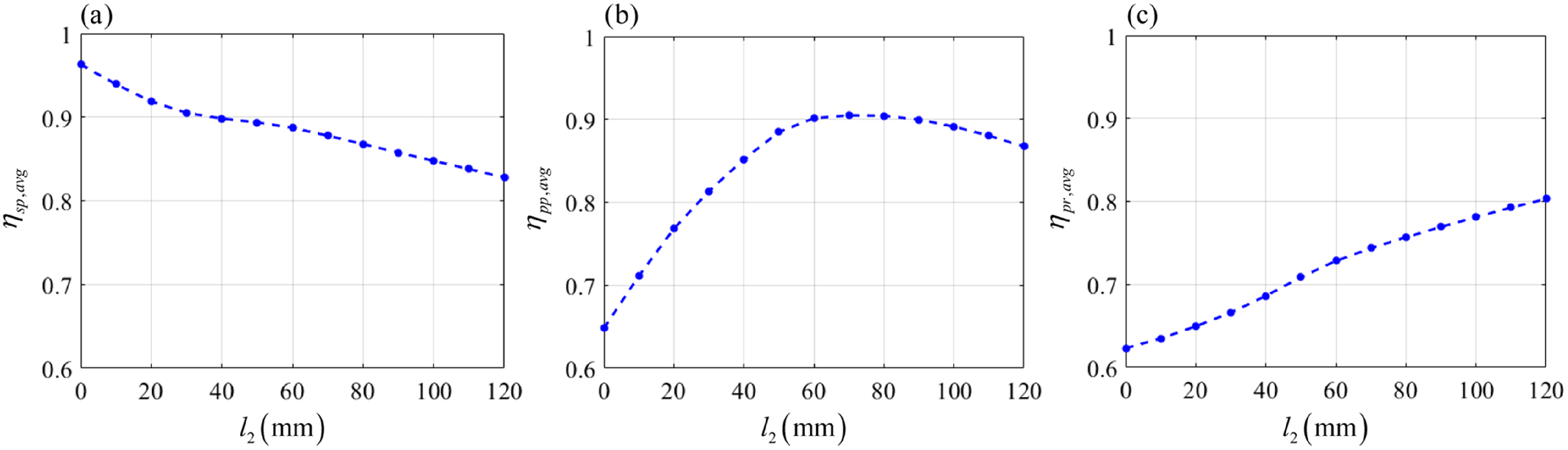
According to Eq. (15), the variations in the global force/motion transmission indices
 $\eta _{sp,avg} , \eta _{pp,avg}$
and
 $\eta _{pr,avg}$
with
 $l_{2}$
, within the given range, are evaluated (Figure 12). The maximum
 $\eta _{pp,avg}$
is
 ${\eta }_{\max }^{pp,avg}=0.905$
when
 $l_{2}=70.8\,\mathrm{mm}$
. Notably, as
 $l_{2}$
increases, the variation in
 $\eta _{pp,avg}$
first increases but then decreases. Furthermore, when
 $l_{2}=0 , \eta _{sp,avg}$
reaches its maximal value
 ${\eta }_{\max }^{sp,avg}=0.963$
and
 $\eta _{pr,avg}$
reaches its minimal value
 ${\eta }_{\min }^{sp,avg}=0.623$
.
 $\eta _{sp,avg}$
and
 $\eta _{pr,avg}$
exhibit opposite variation trends; specifically,
 $\eta _{sp,avg}$
decreases with
 $l_{2}$
, whereas
 $\eta _{pr,avg}$
increases with
 $l_{2}$
. These results indicate a strong correlation between the offsets and the kinematic performance of the parallel mechanism, which can be further utilized in the optimal design of this parallel mechanism in our future work.
Variations in global indices for the mechanism with different offsets. (a)
 $\eta _{sp,avg}$
. (b)
 $\eta _{pp,avg}$
. (c)
 $\eta _{pr,avg}$
.

5. Conclusions
In this work, the kinematics and force/motion transmissibility of a parallel mechanism with offset joints are systematically investigated. The following conclusions are drawn.
-
1. On the basis of the analysis of the geometric relationships among the limbs, a set of equations incorporating dimensional constraints and orthogonality conditions is formulated. Thus, inverse kinematic model of the mechanism can be established through the 15 equations with 15 unknowns. The positions of key reference points and the defined unit vectors can be evaluated numerically.
-
2. According to screw theory and linear algebra, the steps for determining the specific basis elements of the twist and wrench spaces of the limbs are presented. When the wrench of constraints imposed by each limb is a general screw, the constrained mobility can be defined as screw motion that is coaxial and collinear with the same pitch. When the wrench of constraints degenerates into a line vector, the constrained mobility exhibits translational motion in the form of a unit couple. These variations are related to the configurations of the mechanism.
-
3. A comparative analysis of force/motion transmissibility is conducted for mechanisms with different offsets. The results demonstrate that the offsets in the spherical joints can increase the force transmissibility of the mechanism compared to the case without offsets, although the motion transmissibility in the joint space is slightly reduced.
Author contribution
Cui YZ: Conceptualization, Methodology, Software, Writing – original draft. Liu HT: Methodology, Validation, Writing – review & editing. Ma Y: Validation, Writing – review & editing. Liu Q: Validation, Writing – review & editing. Guan Y: Validation, Writing – review & editing. Gao F: Supervision, Writing – review & editing. Niu SC: Supervision, Writing – review & editing. All authors read and approved the final manuscript.
Competing interests
The authors declare that there are no potential conflicts of interest with respect to the research, authorship, and/or publication of this article.
Data availability statement
The datasets used and/or analyzed during the current study are available from the corresponding author on reasonable request.
Funding statement
This work is partially supported by the National Natural Science Foundation of China under grants U24B2047 and 52325501.
Appendix A
Using the inverse kinematic model of the 3-PRRU parallel mechanism derived in Section 2, a kinematic analysis is conducted, and the model’s effectiveness is validated through the commercial software SolidWorks. Given the dimensional parameters provided in Section 3, the analysis is performed with
 $r_{Qz}=400\text{ mm}$
and
 $\theta =30^{\circ }$
held constant and
 $\psi$
subject to
 $\psi =\pi t/3,t\in [0,6]\ \mathrm{s}$
. As the moving platform follows the trajectory, the kinematic parameters of the actuated joints in each limb can be determined by the kinematic model, as shown in Fig. A.1. The theoretical results show no significant difference from those obtained using the Motion Simulation module in the commercial software SolidWorks, demonstrating the validity of the kinematic model.
The kinematic parameters of the actuated joints. (a) Limb 1. (b) Limb 2. (c) Limb 3.


 |hwc,1,1|
 |htc,1,1|

 ψ=0∘,θ=0∘
 ψ=60∘,θ=20∘
 ψ=180∘,θ=20∘
 ψ=300∘,θ=20∘


 ηo

 ηsp
 ηpp
 ηpr

 ηsp
 ηpp
 ηpr


 ηsp,avg
 ηpp,avg
 ηpr,avg



