
Introduction
Electrocatalytic oxidation of small organic molecules on various materials or substrates is receiving tremendous attention due to its applications in various fields including biosensors, fuel cells, energy conversion devices, etc.[Reference Liu, Cao, Kong, Du, Asiri, Lu and Sun1–Reference Yang, Cho and Lee6] Till date, various precious and non-precious metals and their oxides or hydroxides have been intensively pursued as efficient electrocatalysts.[Reference Kaur, Prathap and Srivastava4–Reference Danaee, Jafarian, Forouzandeh, Gobal and Mahjani8] Among those materials, nickel (Ni) and Ni-based materials have high electrocatalytic oxidation activity for various small molecules such as hydrogen peroxide, glucose, dopamine, and methanol.[Reference Yang, Cho and Lee6–Reference Lata, Batra, Karwasra and Pundir10] The electrocatalytic performances of these Ni-based electrocatalysts are closely associated with their structure and the mode of preparation.[Reference Yang, Cho and Lee6, Reference Roychoudhury, Prateek, Basu and Jha9, Reference Niu, Lan, Zhao and Chen11] It has been found that the electrodes modified with porous structures are likely to have an enhanced electrochemical performance, due to its large surface area and easy mass and electron transport at electrode–electrolyte interfaces.[Reference Niu, Lan, Zhao and Chen11] Additionally, in order to further improve the catalytic performance of these Ni-based porous catalysts, several researchers investigated the modification method by means of incorporating noble metals, metal nanoparticles, and other catalytic active materials such as carbon nanotubes, graphene, and so on.[Reference Li, Xia, Lv, Zhao, Yuan and Pang12–Reference Choi, Kim, Lee, Kim, Choi, Kim, Kim, Park and Kim15] The advantages of these modifications are in its improved electrocatalytic activity, stability, and selectivity, which make them promising electrocatalysts for small molecules oxidation. However, the synthesis and fabrication of these Ni-based nanocomposites include laborious multistep complex processes, which may hamper their real-time applications.[Reference Zhang, Lei, Wu, Xia and Hao13–Reference Choi, Kim, Lee, Kim, Choi, Kim, Kim, Park and Kim15] Hence, it is of particular significance to undertake research for the development of reliable, simple, and alternative methods to realize Ni-based hybrid materials.
Electrocatalytic oxidation of small organic molecules such as methanol and glucose is highly useful in the development of fuel cells and sensors.[Reference Wu, Liu, Tian, Cai, Ye, Yuan and Liang3, Reference Cui, Li, Ding, Zhang, Wu and Hu16, Reference Antolini and Gonzalez17] Recently, significant efforts have been underwent on the development of efficient and low-cost electrocatalysts for fuel cell reactions.[Reference Antolini and Gonzalez17] Usually expensive platinum (Pt) and Pt-based catalysts are required to overcome the sluggish anode (oxidation of hydrogen/methanol/hydrazine) and cathode (oxygen reduction reaction) reaction kinetics in acidic medium.[Reference Zhao, Yin, Ma, Liang, Liu, Liao, Lu and Xing18] Furthermore, these precious metals are confronted by problems such as carbon monoxide poisoning and methanol crossover.[Reference Antolini and Gonzalez17–Reference Varcoe and Slade19] These are the major problems associated with the large-scale commercialization of proton exchange membrane fuel cells (PEMFCs).[Reference Varcoe and Slade19] Since the electro-oxidation of organic compounds and oxygen reduction reaction are more facile in alkaline medium than acidic medium, fuel cells based on alkaline electrolyte brought a new hope in fuel cell research.[Reference Slade, Kizewski, Poynton, Zeng and Varcoe20] The main advantage of alkaline polymer electrolyte fuel cell (APEFCs) is the use of non-precious metal catalysts for both anodic and cathodic reactions.[Reference Lu, Pan, Huang, Zhuang and Lu21] Though APEFCs have an edge over PEMFCs, it is necessary to have highly active and stable catalysts for the commercialization of APEFCs.
Methanol (CH3OH), a commonly used source of hydrogen in APEFCs, can be stored safely than pure hydrogen.[Reference Liu, Song, Zhang, Zhang, Wang and Wilkinson22] Direct alcohol fuel cells have higher power density than hydrogen fuel cells,[Reference Bianchini and Shen23] which makes them suitable for the development of fuel cell vehicles. Palladium and Ni-based catalysts are found to be active for methanol oxidation in alkaline conditions.[Reference Bianchini and Shen23–Reference Chen and Minteer26] However, the activity and stability of these catalysts in these harsh alkaline conditions need to be improved for the construction of a low-cost sustainable alkaline fuel cell.
Efficient glucose oxidation is not only important in glucose sensing, but also relevant in the development of renewable and sustainable bio-fuel cells.[Reference Cui, Li, Ding, Zhang, Wu and Hu16, Reference Bahar and Yazici27] Several bio-enzymatic (peroxidase/oxidase) amperometric biosensors and enzymatic fuel cells have been reported for this purpose.[Reference Bahar and Yazici27, Reference Leech, Kavanagh and Schuhmann28] However, the enzymatic sensors suffer from unavoidable issues such as instability, deactivation, and denaturing of the enzymes at high temperatures, which limit their practical applications.[Reference Toghill and Compton29, Reference Si, Huang, Wang and Ma30] Since non-enzymatic glucose sensors are free from these above lacunae, development of non-enzymatic oxidative sensing platforms having efficient catalysts is highly important.[Reference Yang, Cho and Lee6, Reference Radhakrishnan and Kim14, Reference Si, Huang, Wang and Ma30]
In the present study, we demonstrate a simple, scalable, and economically feasible method for the development of a composite catalyst ink—based on Ni-reduced graphene oxide (Ni-rGO) foam, by a modified polyol method (Scheme S1, Supplementary information). Ethylene glycol acts as a medium for both dissolving Ni nitrates and dispersing GO, and at the same time serves as a fuel for the combustion process.[Reference Philip, Narayanan, Kumar, Aryaa and Pattanayak31] A porous foam-like (light-weight) hybrid composite is resulted from this method, and this composite showed an enhanced methanol and glucose oxidation efficacy in alkaline electrolyte due to synergistic effect of its high surface area and better transport properties than Ni foam. This demonstrates a simple but hybrid composite system of Ni and rGO toward small molecule catalytic sensing and oxidative processes developed via a simple route, which otherwise need to be produced using multistep complex procedures such electrodeposition followed by graphene growth via chemical vapor deposition or transfer of graphene on to developed Ni foam.
Experimental section
Materials
Analytical grade Ni (II) nitrate hexahydrate [Ni(NO3)2.6H2O] and graphite powders were procured from Merck India Pvt. Ltd, India. Ethylene glycol, sulfuric acid (H2SO4, 95–98%), and phosphoric acid (H3PO4, 99%) were purchased from Sigma Aldrich, India. Potassium permanganate (KMnO4), hydrogen peroxide (H2O2, 30%), and hydrochloric acid (HCl, 36.5–38%) were purchased from Fine Chem Ltd., India. All the chemicals and reagents were used without any further purification. Deionized water of resistivity 18.2 MΩ.cm from Millipore Milli Q system was used for both synthesis and electrochemical analyses.
Synthesis of GO powder
The GO was prepared by following Improved Hummers method.[Reference Marcano, Kosynkin, Berlin, Sinitskii, Sun, Slesarev, Alemany, Lu and Tour32] For this, 3 g of graphite powder was oxidized in a mixture of concentrated H2SO4 and H3PO4 of ratio 9:1, and to this mixture, 18 g of KMnO4 was added very slowly with continuous magnetic stirring. The solution was kept under constant magnetic stirring at 50 °C for overnight (12–14 h). Then the reaction mixture was cooled to room temperature and poured into ice bath with 3 mL of 30% H2O2 solution. The obtained black precipitate is vacuum filtered and washed with 30% HCl, deionized water, ethanol, and water successively. The washing process was repeated for three times. Finally, the obtained sample was vacuum dried and grinded into powder.
Synthesis of Ni and Ni-rGO foams
A modified polyol process was utilized to develop light-weight Ni and Ni-GO foams.[Reference Philip, Narayanan, Kumar, Aryaa and Pattanayak31] In this synthesis process, 5 g of Ni(NO3)2.6H2O was dissolved in 2.5 mL of ethylene glycol and 190 mg of GO was dispersed into this solution. The mixture was further ultrasonicated for 30 min. A glass petri dish is pre-heated to 250 °C using a hot plate and the above dispersion is poured on to this pre-heated petri dish. Immediately after the addition, the solution caught fire and burnt with a reddish flame. The process resulted in to the formation of metallic Ni foam covered with rGO. For the fabrication of Ni foam (low-density mechanically fragile sponges), the same experiment was performed without GO. Both the samples were collected and ground in to fine powders. These fine powders are further used for electrochemical studies.
Instrumentation
The structural and morphologic properties of the Ni and Ni-GO foams were studied using scanning electron microscope (SEM), Carl Ziess's (Sigma 300) field-emission scanning electron microscope (FE-SEM). Micro-Raman spectroscopic measurements were performed using inVia Raman microscope (Renishaw plc, UK) with an excitation laser source of 532 nm. All the electrochemical measurements were performed in a conventional three-electrode setup at room temperature using the Bio-Logic potentiostat (model SP300). A standard calomel electrode (SCE) and a Pt wire were used as a reference and counter electrode, respectively. The inks of Ni and Ni-rGO foams-modified glassy carbon (GC) electrodes were used as the working electrodes (the ink preparation is explained in the next section). All electrochemical measurements were carried out in 0.1 M NaOH solution, and before experiments, the electrolyte solution was de-aerated by bubbling with high purity nitrogen for 30 min. The voltage scale is converted to the reversible hydrogen electrode (RHE) scale according to the Nernst equation,
 $$E_{{\rm RHE}} = E_{{\rm SCE}} + E_{{\rm SCE}}^0 + 0.059 \times {\rm pH,}$$
where, E SCE0 = 0.244 at 25 °C, and E SCE is the experimentally measured potential.
Fabrication of the working electrodes
The fabrication of the Ni and Ni-rGO-modified electrodes were carried out as follows: the surface of the GC (3 mm diameter) electrode was mechanically cleaned by polishing with the alumina powder (<50 nm) followed by its washing in water. The catalyst ink was prepared by dispersing 4 mg of respective samples (Ni or Ni-rGO foam) in water (1 mL) and Nafion solution (20 µL of 5 wt.%) under sonication for 30 min. A 10 µL of above aliquot was then drop casted onto the surface of clean GC electrode (labeled as GC/Ni-rGO or GC/Ni) and dried at room temperature.
Results and discussion
Physico-chemical characterizations of the Ni and Ni-rGO foams
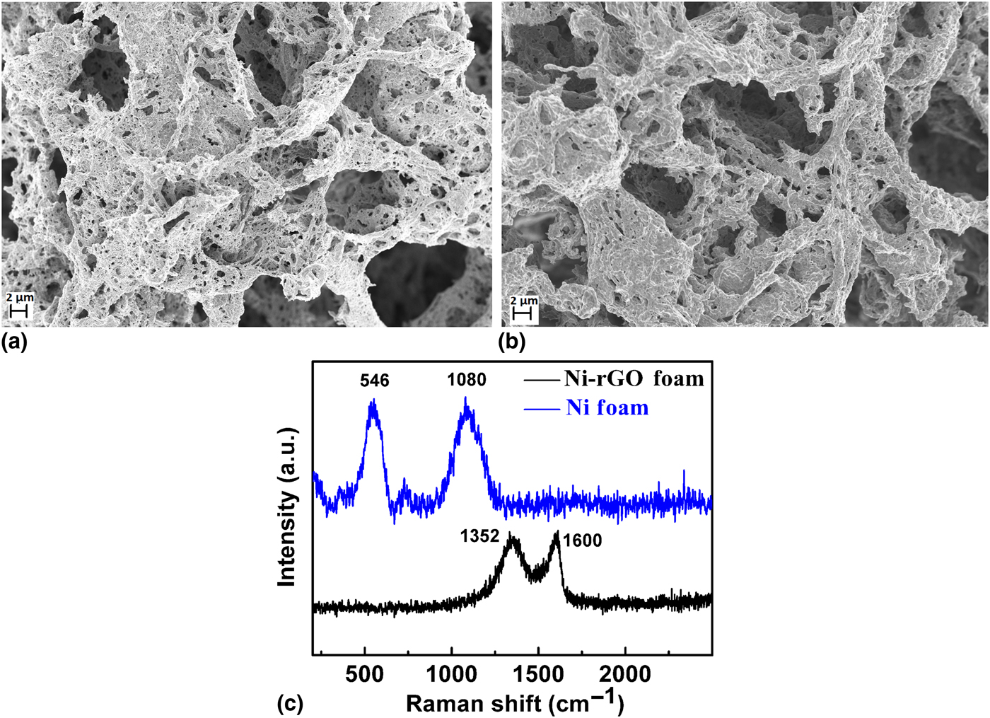
The formation of Ni and Ni-rGO composite foams were reported in our previous report.[Reference Philip, Narayanan, Kumar, Aryaa and Pattanayak31] In that report, the x-ray diffraction (XRD) studies on the pattern of Ni foam show the presence of cubic Ni (2θ = 44.8, 52.2, 76.6, and 93.2) as well as peaks of Cubic NiO (2θ = 37.2, 43.3, and 62.9).[Reference Philip, Narayanan, Kumar, Aryaa and Pattanayak31] On the other hand, no peaks for cubic NiO were found to be present on the XRD pattern of Ni-rGO foam. This indicates either no NiO formation in the presence of rGO or <2 wt.% of NiO formation, which is below the detection limit of XRD. Here, the structural and morphological analyses of the Ni and Ni-GO foams are carried out by FE-SEM and is depicted in Fig. 1. From the SEM images, it is evident that both Ni [Fig. 1(a)] and Ni-rGO [Fig. 1(b)] foams are having highly porous structure having micro-porosity. Such a unique porous structure of Ni and Ni-GO foams can provide high surface area for the mass transportation of reactants and analytes, which can be beneficial for the electrocatalytic studies.
SEM images of (a) Ni and (b) Ni-rGO foams, (c) micro-Raman spectra of as-synthesized Ni and Ni-rGO foams.

Further, to confirm the presence of GO on Ni-rGO composite foam, micro-Raman spectroscopic measurements are carried out. Figure 1(c) shows the Raman spectra of the as-synthesized Ni and Ni-GO foams. The micro-Raman spectrum of only Ni foam shows mainly two strong peaks at 546 and 1080/cm that can be attributed to the one-phonon (1P) transverse optical (TO) mode and two-phonon 2LO (longitudinal optical) mode of NiO, respectively.[Reference Huang, Ding, Chen, Hao, Lai, Peng, Tu, Cao and Li33] However, the spectrum for Ni-rGO shows two distinct peaks at 1350 and 1600/cm that can be attributed to disorder (D-band) and graphitic (G-band) peaks of GO, respectively.[Reference Philip, Narayanan, Kumar, Aryaa and Pattanayak31, Reference Huang, Ding, Chen, Hao, Lai, Peng, Tu, Cao and Li33] The absence of NiO peaks in Raman spectra of Ni-rGO further validates and confirms the absence of NiO layer formation on Ni-rGO surface. The broad and relatively high-intense D peak shows the formation of reduced GO during the formation of Ni-rGO composite from Ni salt and GO.
Electrochemical characterizations
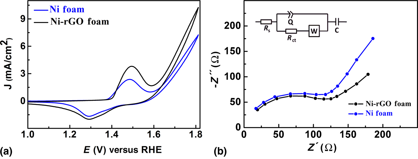
The electrochemical and charge transfer properties of the fabricated GC/Ni and GC/Ni-rGO electrodes are examined by cyclic voltammetry (CV) and electrochemical impedance spectroscopy (EIS) techniques. The CVs of 50 consecutive potential sweeps from 1.0 to 1.8 V (versus RHE) in 0.1 M NaOH at a scan rate of 50 mV/s are recorded to get the stable electrochemical response (activation of the electrode). Figure 2(a) depicts the stable potential sweep response of GC/Ni and GC/Ni-rGO electrodes in 0.1 M NaOH solution. As one can see from the CV curves, both GC/Ni and GC/Ni-rGO electrodes show an anodic peak at +1.45 V and the corresponding cathodic peak at +1.30 V. This obtained redox behavior of modified electrodes demonstrates the one electron redox chemistry of Ni2+/Ni3+and formation of Ni oxyhydroxide in alkaline solution,[Reference Danaee, Jafarian, Forouzandeh, Gobal and Mahjani8] as shown in Eqs. (2) and (3):
 $${\rm Ni} + 2{\rm O}{\rm H}^{-} \to {\rm Ni}({\rm OH})_2 + 2{\rm e}^{-}, $$
 $${\rm Ni}({\rm OH})_2 + {\rm O}{\rm H}^{-} \mathbin{\lower.3ex\hbox{$\buildrel\textstyle\rightarrow\over {\smash{\leftarrow}\vphantom{_{\vbox to.5ex{\vss}}}}$}} {\rm NiOOH} + {\rm H}_{\rm 2}{\rm O} + {\rm e}^{-} $$
(a) CVs of GC/Ni and GC/Ni-rGO at a scan rate of 20 mV/s in 0.1 M NaOH, (b) Nyquist diagrams for the GC/Ni and GC/Ni-rGO obtained in 5.0 mM [Fe(CN)6]3−/4− containing 0.1 M KCl at formal potential, frequency range: 100 KHz to 0.1 Hz, amplitude: 10 mV.

Furthermore, the CV responses of both the electrodes obtained at different scan rates in 0.1 M NaOH are recorded and shown in Supplementary information (Figs. S1 and S2). It can be seen that the redox peak currents increase linearly with increase in scan rates, suggesting that the electron transfer for the Ni2+/Ni3+ redox couples takes place through a diffusion-controlled mechanism.[Reference Kaur, Prathap and Srivastava4]
The electron transfer properties of the fabricated GC/Ni and GC/Ni-rGO electrodes are studied by EIS experiments. Figure 2(b) shows the EIS spectra (Nyquist plot) of GC/Ni and GC/Ni-rGO electrodes taken in 5 mM Fe(CN)63−/4− solution at formal potential. The Nyquist plots of GC/Ni and GC/Ni-rGO [Fig. 2(b)] consist of semi-circle part lying at higher frequencies, followed by a straight line at lower frequencies. The semi-circular part corresponds to the charge transfer-limited process and its diameter is equivalent to the charge transfer resistance (R ct), which normally reflects the conductivity and the electron transfer process. A straight line indicates the diffusion-limiting step in the electrochemical process. Nyquist diagrams are fitted with the Randles equivalent circuit. Inset of Fig. 2(b) shows the best-fitted Randles equivalent circuit. The obtained R ct value from the fitting result can be used to describe the interface properties of the electrode. The R ct values for the GC/Ni and GC/Ni-rGO electrodes are found to be 120 and 95 Ω, respectively. A comparatively high R ct value of GC/Ni in comparison with GC/Ni-rGO implies that the presence of rGO over Ni foam certainly playing an important role in enhancing the electrical conductivity of the electrode and accelerating the electron transfer process.
Electrocatalytic oxidation of methanol
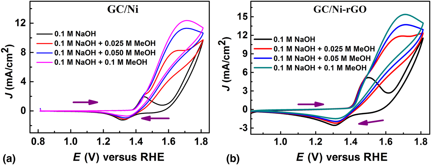
Figure 3 shows the CVs of GC/Ni and GC/Ni-rGO electrodes in 0.1 M NaOH with and without methanol. In the absence of methanol, a redox response corresponding to the oxidation of Ni(OH)2 to NiOOH and the reduction of NiOOH to Ni(OH)2 is observed as previously mentioned. However, when we introduce methanol in to the electrolyte, a new anodic peak that corresponds to methanol oxidation is observed at 1.65 V and the intensity of this peak successively increases with the incremental addition of methanol [Figs. 3(a) and 3(b)]. At lower methanol concentration (0.025 M), clear cut separation between the peaks of NiOOH formation and methanol oxidation can be observed. This result clearly suggests that methanol oxidation occurs after the formation of NiOOH. At higher concentration of methanol (0.05 M and above), the separation between the peaks are not well defined and they almost merge together at higher concentration. Moreover, the intensity of cathodic peak resultant of the reduction of NiOOH to Ni(OH)2 also reduces with the addition of methanol. This may be due to the partial reduction of NiOOH by methanol.[Reference El-Shafei34]
CV of (a) GC/Ni and (b) GC/Ni-rGO electrodes in 0.1 M NaOH with different concentration of methanol at a scan rate of 20 mV/s.

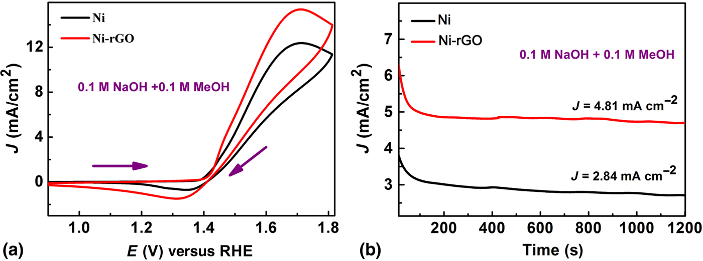
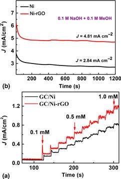
In order to compare the electrocatalytic performance of GC/Ni and GC/Ni-rGO electrodes for methanol oxidation, the CVs of GC/Ni and GC/Ni-rGO electrodes in the presence of 0.1 M methanol are performed [Fig. 4(a)]. From Fig. 4(a), it can be seen that the GC/Ni-rGO electrode is producing the high electrocatalytic current response compared with the GC/Ni electrode. This result clearly suggests that the as-synthesized Ni-rGO foam has better electrocatalytic ability over Ni-foam toward methanol oxidation. Further, the stability of GC/Ni and GC/Ni-rGO electrodes toward methanol oxidation is examined by the chronoamperometric studies. Figure 4(b) shows the chronoamperometry results of GC/Ni and GC/Ni-rGO electrodes in 0.1 M NaOH at an applied potential of 1.6 V. It can be seen that the GC/Ni-rGO is fairly more stable than the GC/Ni electrode. The methanol (0.1 M) oxidation current density of GC/Ni-rGO is found to be 4.81 mA/cm2, which is ~1.7 times higher than that of GC/Ni electrode recorded in the similar situation. Thus, the observed high electrocatalytic current in CV and chronoamperometric results confirm that the as-synthesized Ni-rGO foam possess an excellent electrocatalytic performance for methanol oxidation in alkaline medium.
(a) CV and (b) chronoamperometric response of GC/Ni and GC/Ni-rGO electrodes in 0.1 M NaOH containing 0.1 M methanol, scan rate of 20 mV/s.

Electrocatalytic oxidation of glucose
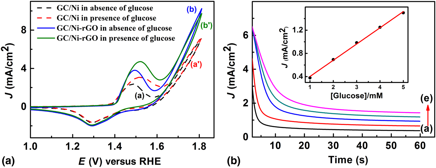
In order to assess the broad applicability of the synthesized Ni-rGO material in other oxidative sensing processes, and also taking into account the known electrocatalytic activity of Ni towards the non-enzymatic detection of glucose in alkaline medium, we further evaluated the catalytic ability of the fabricated GC/Ni-rGO electrode for glucose oxidation. Figure 5(a) shows the comparative CV responses of the GC/Ni and GC/Ni-rGO electrodes recorded with and without the presence of 1.0 mM glucose in 0.1 M NaOH at a scan rate of 20 mV/s. The CV response of GC/Ni and GC/Ni-rGO in the absence of glucose [Fig. 5(a), curves a and b] shows the redox behavior associated with Ni as discussed in the previous section. Whereas in the presence of 1.0 mM glucose [Fig. 5(a), curves a′ and b′], an enhanced anodic current, starting from the potential of 1.4 V, is observed in both the electrodes due to glucose oxidation electro catalyzed by the electrode surface.[Reference Danaee, Jafarian, Forouzandeh, Gobal and Mahjani8, Reference Radhakrishnan and Kim14] The probable mechanism of electrocatalytic glucose oxidation at these modified electrodes is similar to the previously reported glucose oxidation[Reference Kaur, Prathap and Srivastava4, Reference Radhakrishnan and Kim14] and can be interpreted as follows:
 $${\rm Ni}({\rm OH})_2 + {\rm O}{\rm H}^{-} \to {\rm NiOOH} + {\rm H}_2{\rm O} + {\rm e}^{-}, $$
 $${\rm NiOOH} + {\rm glucose} \to {\rm Ni(OH} )_2 + {\rm glucolactone}. $$
(a) CVs of GC/Ni (a and a′) and GC/Ni-rGO (b and b′) electrodes in 0.1 M NaOH with a scan rate of 20 mV/s in the absence (a and b) and in the presence (a′ and b′) of 1.0 mM glucose. (b) Chronoamperometric responses for GC/Ni-rGO at different concentrations of glucose (a→e correspond to 1, 2, 3, 4, and 5 mM of glucose).

In contrast to GC/Ni, the GC/Ni-rGO [Fig. 5(a)] shows the higher current response of glucose suggesting that the GC/Ni-rGO electrode possess a better electrocatalytic ability and high sensitivity toward glucose oxidation. The high anodic current response at the GC/Ni-rGO electrode is attributed to the synergistic effect imparted from (i) excellent electron transport property of Ni-rGO, which promotes electron transfer of glucose (where rGO forms interconnected the network between different Ni grains), and (ii) the electrocatalytic ability of Ni. The electrocatalytic efficiency of glucose oxidation at the surface of the GC/Ni-rGO is also studied by chronoamperometry technique and depicted in Fig. 5(b). The chronoamperometry current responses [Fig. 5(b)] are increase continuously with the successive addition of glucose ranging from 1 to 5 mM. The current response sampled at 60 s against the concentration of glucose shows a linear response [inset of Fig. 5(b)], which further suggests that the GC/Ni-rGO electrode can be used as a sensing platform for the glucose determination.
Amperometric determination of glucose
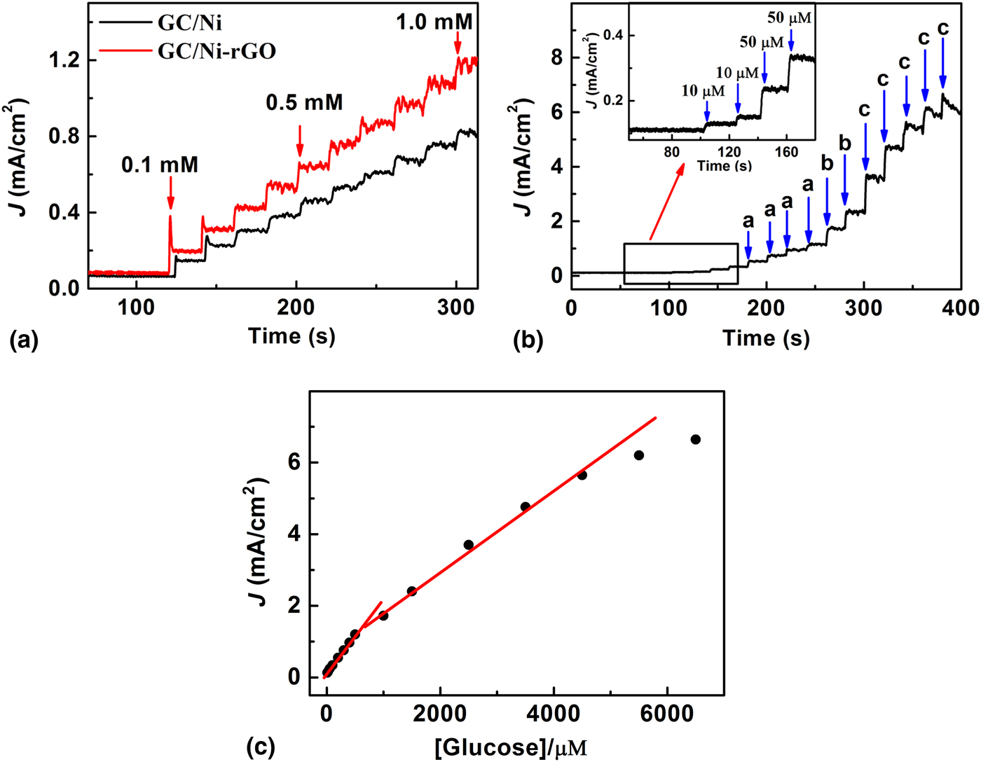
The evidence from CV alone is not sufficient to decide a better sensitivity of GC/Ni-rGO over GC/Ni electrode towards the glucose oxidation. Hence, amperometric experiments are performed on both the electrodes with continuous addition of 100 µM glucose at an applied potential of +1.56 V. Figure 6(a) shows the current–time profile for both the electrodes with successive addition of glucose with an interval of 20 s. From the current–time graphs, it is evident that the GC/Ni-rGO electrode is giving better current response for similar glucose additions and has a better sensitivity compared with the GC/Ni electrode.
(a) Amperometric response of GC/Ni and GC/Ni-rGO electrodes to the successive additions of 100 µM glucose at an applied potential of +1.5 V. (b) Amperometric response of GC/Ni-rGO electrodes to the successive additions of glucose at an applied potential of +1.5 V (a, b, and c correspond to the addition of 0.1, 0.5, and 1 mM of glucose, respectively). (c) Shows the corresponding calibration plot of the GC/Ni-rGO electrode at different concentrations of glucose.

Further, another amperometric study is carried out to evaluate the sensitivity of the GC/Ni-rGO-modified electrodes towards glucose determination. Figure 6(b) shows the amperometric response of GC/Ni-rGO upon successive additions of glucose in to a homogeneously stirred 0.1 M NaOH solution at an applied potential of +1.56 V. The fabricated GC/Ni-rGO sensing platform exhibits a very fast response to the changes of glucose concentration and attains the steady-state response within 5 s. Under these conditions, the GC/Ni-rGO electrode shows an initial response due to 10 µM glucose and on adding different amounts of glucose in each step with a sample interval of 20 s, the current response increases steadily. Based on the amperometric current response, a calibration curve for glucose sensing is plotted and shown in Fig. 6(c). The calibration curves exhibit two linear ranges with the concentration ranges from 10.0 × 10⁻⁶ to 1.0 × 10⁻³ M and from 1.0 × 10⁻³ to 4.5 × 10⁻³ M, respectively. Above 4.5 × 10⁻³ M concentration, the current increases and approaches a plateau, which probably is due to saturation of the catalytic active site of the electrode surface. The sensitivity and detection limit (taken as 3 σ/S, where σ is the standard deviation of the blank signal and S the sensitivity) are calculated to be 124.8 µA/mM/cm2 and 3.6 µM, respectively. The observed wide-linear calibration range along with low detection limit and high sensitivity for glucose sensing at the GC/Ni-rGO electrode are comparable or better than other non-enzymatic glucose sensors reported in the literature.[Reference Kaur, Prathap and Srivastava4, Reference Luo, Zhu and Wang5, Reference Zhang, Lei, Wu, Xia and Hao13–Reference Choi, Kim, Lee, Kim, Choi, Kim, Kim, Park and Kim15]
Conclusions
Composite metal–graphene foams-based inks developed using a modified polyol method followed by dispersion is found to be delivering augmented electrocatalytic performance in glucose and methanol oxidation processes. The conductive rGO network effectively enhances the charge transfer processes in otherwise disjointed Ni grains in Ni foam, and this might be the reason for high sensitivity and large (high current density) electrochemical responses from Ni-rGO foam toward the oxidative processes in comparison with Ni foam. A high methanol (0.1 M) oxidation current density in Ni-rGO is observed (4.81 mA/cm2), which is found to be ~1.7 times higher than that of Ni electrode. Further, the Ni-rGO electrode showed a linear sensing response over a wide concentration of glucose (10 µM to 4.5 mM) with a sensitivity and detection limit of 124.8 µA/mM/cm2 and 3.6 µM, respectively. Hence, this study probes the importance of metal–graphene hybrids in sensing platforms and fuel cell electrodes for improved charge transfer processes and long-term electrode performances. Further, the inks of metal–graphene developed here are patternable using simple lithographic or coating techniques, opening the new avenues of printable sensors and devices using these composite materials.
Supplementary material
The supplementary material for this article can be found at https://doi.org/10.1557/mrc.2018.123
Acknowledgments
S.T. acknowledges the UGC for the fellowship [3976/(NET-JUNE 2013)]. M.R.A. acknowledges UGC (Govt. of India) for UGC-BSR Faculty Fellowship. P.K.R., N.S., and T.N.N. acknowledge TIFR for the financial support. P.K.R. (PDF/2016/001440) and N.S. (PDF/2016/002763) are also thankful to the SERB for providing the national postdoc fellowship. T.N.N. also acknowledge the financial support from DST-SERB Extra-Mural Research Grant (EMR/2017/000513).