
I. INTRODUCTION
Graphene has been proved to hold novel tribological performances at the nano-scale, Reference Ko, Kwon, Byun, Choi, Park, Kim and Park1–Reference Filleter, McChesney, Bostwick, Rotenberg, Emtsev, Seyller, Horn and Bennewitz3 owing to its excellent mechanical properties. Reference Lee, Wei, Kysar and Hone4,Reference Compton and Nguyen5 Meanwhile, due to its nanometer thickness, graphene sheets can be applied to prepare ultra-thin lubricant films Reference Deng, Klimov, Solares, Li, Xu and Cannara6–Reference Berman, Erdemir and Sumant8 for contact surfaces or to act as lubricant additives Reference Dou, Koltonow, He, Jang, Wang, Chung and Huang9 in micro machines, for instance, MEMS. However, because of the chemical inertness of graphene, the bonding strength between graphene and protected surface is not strong enough to prevent wear.
Graphene oxide (GO), as the precursor to obtain graphene, can be used to prepare a covalently bonded GO film on pretreated substrates, and obtain graphene films through surface reduction treatment of GO film. Reference Li, Zhou and Cheng10–Reference Ou, Wang, Liu, Mu, Ren, Wang and Yang13 Those films performed well as lubricate films owing to their strong bonding strength. Noticeably, the surface reduction process played an important role in improving tribological performance by reducing the surface energy of the films. Thus, such a high efficiency method for GO reduction may have the potential for improving the nano-tribological properties of reduced GO films.
A variety of approaches have been developed to reduce GO. Reference Li, Muller, Gilje, Kaner and Wallace14–Reference Stankovich, Piner, Kohlhaas, Kleinhammes and Jia19 However, few of them can be directly applied to reduce GO films for lubrication. There are mainly three reasons: introducing noncarbon impurities into the film, Reference Li, Muller, Gilje, Kaner and Wallace14–Reference Becerril, Mao, Liu, Stoltenberg, Bao and Chen16 damaging the structure of the graphene platelets, Reference Shin, Kim, Benayad, Yoon, Park, Jung, Jin, Jeong, Kim, Choi and Lee17,Reference Gao, Alemany, Ci and Ajayan18 or weakening the bonding strength between GO films and substrates. Reference Yang, Velamakanni, Bozoklu, Park, Stoller, Piner, Stankovich, Jung, Field, Ventrice and Ruoff15,Reference Shin, Kim, Benayad, Yoon, Park, Jung, Jin, Jeong, Kim, Choi and Lee17,Reference Stankovich, Piner, Kohlhaas, Kleinhammes and Jia19 In contrast, hydrothermal Reference Li, Zhou and Cheng10,Reference Zhou, Bao, Tang, Zhong and Loh20 and thermal Reference Li, Zhou and Cheng11,Reference Ou, Wang, Liu, Mu, Ren, Wang and Yang13,Reference Wang, Zhi and Mullen21 methods have been shown to be low-cost and effective methods to reduce GO films, and bring less impurities and harm to the film. Besides, Zhou Reference Zhou, Bao, Tang, Zhong and Loh20 and Pei Reference Pei, Zhao, Du, Ren and Cheng22 found that the addition of HBr, HCl, or HI in hydrothermal treatment can promote the reduction effect. Although they may lead to agglomeration of graphene sheets, it can be helpful for the reduction of GO films, as GO sheets in the form of film are bonded to the substrate without concern of agglomeration of GO sheets.
Moreover, tribological studies of graphene material in liquids are still in their early stages, Reference Robinson, Kay and Kolosov23,Reference Minatchy, Thomas, Bilas, Nomede-Martyr and Romana24 while the research on nano-tribological properties of graphene films in liquids are in urgent need for further application in micro-machines working under water, oil, bio-fluid, and even chemical solutions.
Nano-tribological properties of GO and reduced GO films in liquids can be successfully investigated if they can be strongly anchored to polished silicon substrates. In our previous study, GO sheets can be chemisorbed onto silicon or titanium substrates by using APTES. Reference Li, Zhou and Cheng10–Reference Liu, Shu, Li and Cheng12
In this study, we prepared three types of graphene film: GO film, reduced GO films treated by thermal and hydrothermal reduction methods, which were all chemisorbed onto silicon substrates by using APTES as the interface adhesion layer. To identify the reduction effects of different methods, the surface chemical compositions were characterized by XPS. Their surface adhesion properties and tribological performances were investigated in air and in liquids with different pH values. The adhesive forces and nanoscale friction forces in relation to the pH values of aqueous solutions were discussed in details.
II. EXPERIMENT DETAIL
A. Materials
Expendable graphite was purchased from Nanjing XF NANO Materials Tech Co., Ltd. 3-Aminopropyl triethoxysilane (APTES, 99%, ρ = 0.942 g/ml) was obtained from Aldrich Chemical Co., Inc. Silicon wafers (100) provided by Zhejiang Cubic Crystalline Silicon Materials Co., Ltd were cut into size of 10 × 10 mm and used as the substrates. All other reagents were of analytical grade and used as received. Deionized water was used throughout the whole experiment.
B. Preparation of graphene films
GO colloid solution was prepared by oxidizing expendable graphite based on a modified Hummers method. Reference Li, Zhou and Cheng11,Reference Ou, Liu, Wang, Wang, Xue and Li25 The as-prepared brown colloid solution was diluted with deionized water to obtain a homogeneous, yellow-brown GO dispersion with concentration of 0.05 wt%, which was used in the succeeding processes.
The silicon substrates were prepared following our previous reported method. Reference Liu, Shu, Li and Cheng12 Briefly, highly polished silicon wafers were cleaned ultrasonically with absolute ethanol and deionized water in sequence and then hydroxylated in Piranha solution at 90 °C for 30 min, which was composed of a mixture of 3:1 (v/v) 98% H2SO4 and 30% H2O2, followed by a copious rinsing with deionized water. The piranha-treated silicon wafers were then immersed into prepared APTES solution (0.5 mM in a solvent mixture of acetone and water in volume ratio of 5:1) at ambient atmosphere for 30 min. After being taken out, the wafers were rinsed with deionized water and dried for 1 h at 120 °C under nitrogen atmosphere. In this way, self-assembled multilayers of APTES (coded as APTES-SAM) were formed on silicon wafers.
Subsequently, the silicon substrates with APTES-SAM were kept in previously prepared GO dispersion at 60 °C for 12 h to form our targeted lubricant films, then ultrasonically cleaned with deionized water and dried in N2 stream to remove GO sheets that are not strongly bonded onto the sample. The corresponding film was labeled as APTES-GO film. Finally, those wafers were heated to 200 °C at a rate of 1 °C/min and then kept at 200 °C for 2 h under an argon atmosphere. The thermal reduced graphene film was coded as APTES-RGO film.
For comparison, we prepared hydrothermal reduced GO film by heating APTES-GO film wafers in acid solution (pH = 3) at 135 °C for 12 h in reaction kettle, after a heat-curing process of APTES-GO film at 135 °C for 45 min in vacuum condition. The pH value of the solution was adjusted with hydrochloric acid and ammonia solution. The reaction kettle was then naturally cooled down to room temperature, and the wafers were taken out. After thoroughly cleaned with deionized water and blown dry with N2, the obtained film was coded as APTES-HRGO film.
Through morphology observation, Si wafers can be fully covered by graphene sheets, while overlapping phenomenon of graphene sheets can be easily observed. The nano-tribological results of overlapped graphene film and single layer graphene film may be different. To avoid that variation, the GO adsorption process for friction study was readjusted: the immersion time in GO dispersion was lowered from 12 h to 3 h. In the following nano-tribological study sections, APTES-GO, APTES-RGO, and APTES-HRGO films are all prepared by this method.
C. Characterization
X-ray photoelectron spectroscopy (XPS; AXIS Ultra DLD, Shimadzu Corporation, Kyoto, Japan) was performed to analyze the chemical state of elements in different films. Al Kα radiation was used as the x-ray source for excitation at a power of 150 W and pass energy of 40 eV, and all XPS data presented in this paper were measured at a take-off angle of 0°. The binding energies were calibrated based on the contaminative carbon (C 1s: 284.5 eV).
Nanoscope IIIa multimode atomic force microscopy (AFM; Veeco Instruments Inc., Plainview, New York) was used in tapping mode to characterize the surface morphology. Roughness information of RGO-APTES films are obtained using the “roughness” function of the Nanoscope analysis 1.40 software to analysis the AFM images. Thickness test is detected by a Multi-skop ellipsometer (Optrel, Kleinmachnow, Germany) using a He–Ne laser (632.8 nm) with an incident angle of 70°. The result value is the average value of thickness results of three different tested spots on the same specimen surface.
Water contact angles (WCA) of different samples were determined using a DSA100 contact angle meter (Krüss, Germany) in the environment of 20–25 °C and 30–35% relative humidity. The volume of each deionized water droplet dropped on the films was 5 μL. The reported values for each sample were the average values of at least five measurements at different spots.
D. Nano-tribological properties of the lubrication films
Nano-tribological properties of the three types of graphene films in air or in different pH solutions were measured using the same AFM in contact mode. V-shaped, gold-coated Si3N4 cantilevers with a normal spring constant of around 0.4 N/m and radius of 20–35 nm were used for measurements in air. The lateral spring constant calibrated according to Liu Reference Liu, Wu and Evans26 was equal to 105 N/m. Si3N4 cantilevers with gold-coated reflective back were equipped with a special holder for scanning in aqueous environment to obtain friction and adhesive forces of the three samples. Its normal spring constant, lateral spring constant, and tip radius were about 0.3 N/m, 117 N/m, and 20 nm, respectively. The measurements were performed with all samples and AFM probe immersed in solutions. When the probe slides at a velocity of 1 μm/s with a sliding length of 300 nm, the voltage signals were continuously recorded as a function of linearly increasing loads. The nano friction forces were then quantified using the lateral spring constant and detector sensitivity. The final friction–load curve of each sample was averaged over at least three selected surface areas with smooth topography. Adhesive forces between three graphene film surfaces and AFM probe tips at different pH conditions were calculated using AFM approach–retraction curves, from which the adhesive forces are derived. Each adhesive force was the average of five individual measurements at randomly selected locations. All the measurements were performed at room temperature in the ambient environment of 20–25 °C and 30–40% relative humidity, and all the measured friction–load curves and adhesive forces were obtained as the pH was verified from 2 to 12. The pH values of the solutions were adjusted by 1 M HCl and NaOH. After each measurement, AFM probe tips and samples were thoroughly rinsed with deionized water and dried in a nitrogen stream, and testing tips were changed before obviously contaminated or worn. We also measured the nano friction and adhesive forces of the three films in the same laboratory environment for comparison.
III. RESULTS AND DISCUSSION
A. Water contact angle and chemical characterization
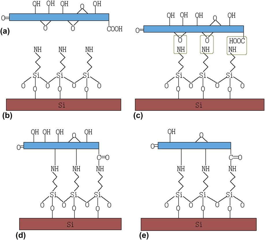
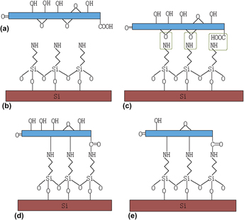
It is widely accepted that GO holds its structure with hydroxyl and epoxy group on the plane while carboxyl and carbonyl groups at the edge of graphene sheet. Reference Dreyer, Park, Bielawski and Ruoff27,Reference Lerf, Forster and Klinowski28 The epoxy group and carboxyl group can react with the terminal amino group of the APTES. Reference Song, Chu, Zhou, Yang and Zhang29,Reference Gao, Jang and Nagase30 Making use of those reactions, we covalently bonded GO onto silicon wafers. A schematic diagram of the chemical structure of samples and the reaction between GO and APTES-SAM can be seen in Fig. 1.
(a) Proposed chemical structure of GO; (b) APTES-SAM on silicon substrate; (c) illustration of the reaction between GO and APTES; (d) APTES-GO film on substrate; and (e) APTES-RGO or APTES-HRGO film on silicon substrate.

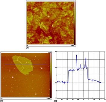
To confirm the surface information of the film, AFM was used to observe the morphology of APTES-GO film, as shown in Fig. 2. With 12 h immersion time as shown in Fig. 2(a), the substrate was fully covered with GO sheets (overlapping areas can be easily observed), indicating that lubricate graphene film can be successfully obtained by this method, with the roughness of R q = 0.872 nm. The thickness of APTES-GO films is about 3.8 ± 0.6 nm, detected by a ellipsometer. With 3 h immersion time as shown in Fig. 2(b), GO sheets can be found on the wafer with much less overlapping phenomenon. The case of Fig. 2(b) is more suitable for nano-tribological test to avoid the disturbance of two layered graphene sheets (overlapping).
AFM image of APTES-GO films with immersion time 12 h (a), 3 h (b), and section analysis data of (c).

WCA measurement was performed to obtain the wetting ability of samples. As Table I shows, the static water contact angle of the hydroxylated silicon substrate is less than 10°, indicating the silicon substrate was thoroughly hydroxylated after pretreatment in Piranha solution. After chemo-grafting with APTES-SAM and APTES-GO, the contact angles increased to 53.6° and 61.2°, respectively. The hydrophilicities of these samples are attributed to the terminal amino groups of APTES-SAM and the oxygenous groups on APTES-GO films. The contact angle of APTES-RGO sharply increased to 93.5°, which can be explained by the disappearance of most oxygenous groups on GO sheets caused by thermal reduction. It should be noticed that, compared with APTES-RGO film, APTES-HRGO film exhibited a higher hydrophobicity, suggesting that the number per unit area of oxygenous groups on APTES-HRGO film is lower than that of APTES-RGO film. This phenomenon demonstrated that the deoxidation effect of hydrothermal reduction is better than thermal reduction, which can be further substantiated by XPS analysis.
WCA for various samples.

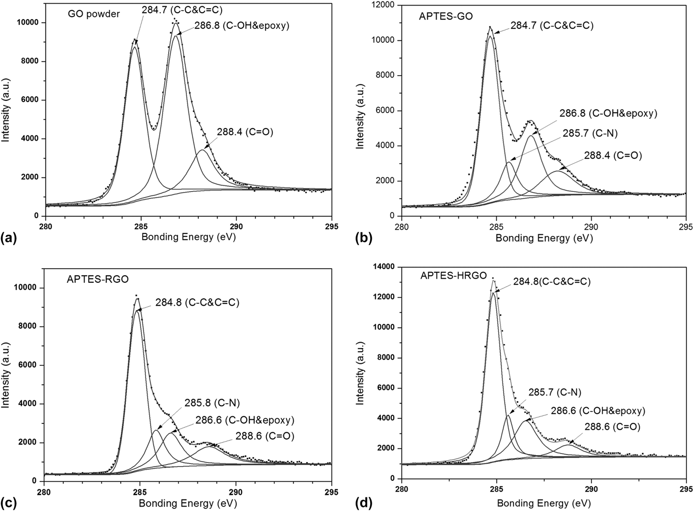
XPS analysis was used to gain insight into the chemical composition of the samples. Figure 3 shows the C 1s spectra of GO powder, APTES-GO film, APTES-RGO film, and APTES-HRGO film. As depicted in Fig. 3(a), the three deconvoluted peaks in the C 1s spectra of GO powder correspond to carbon atoms in different functional groups: the C in C–C/C=C (284.7 eV), in C–OH/C–O (286.8 eV), and in C=O (288.4 eV). This is consistent with the commonly agreed GO chemical structure model, a significant fraction of the sp 2-bonded carbon network bonded with hydroxyl groups and epoxy groups on the basal plane, while minor carboxyl groups or carbonyl groups located on the graphene sheet edges. Reference Dreyer, Park, Bielawski and Ruoff27,Reference Park and Ruoff31 Compared with GO powder, the C 1s XPS spectrum of APTES-GO [Fig. 3(b)] exhibits similar oxygenous groups, but their peak intensities are much weaker. Additionally, there is a new component at a bonding energy of 285.7 eV, which is believed to be C–N bond according to Refs. Reference Becerril, Mao, Liu, Stoltenberg, Bao and Chen16, Reference Li, Xu and Cheng32, and Reference Su, Xu, Zhang, Zhao, Tang, Tsai and Li33. The sharp decrease in proportion of oxygenated carbon and the new emerging C–N peak strongly indicate that the amino groups of APTES have reacted with epoxy groups and carboxyl groups on GO sheets.
XPS spectra of C 1s for (a) GO powder, (b) APTES-GO film, (c) APTES-RGO film, and (d) APTES-HRGO film.

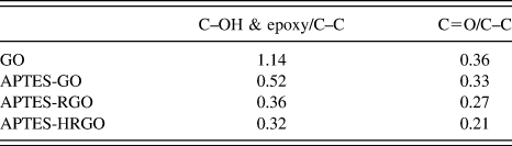
After reduction, the oxygen functional components of APTES-HRGO and APTES-RGO [Fig. 3(c)] are dwarfed by APTES-GO, and the graphite carbon dominates. The significantly shrinking areas are the C–O components of APTES-RGO and APTES-HRGO, meanwhile C=O peaks also get slightly smaller, which strongly indicates that these two reduction methods have removed most hydroxyl groups and some carboxyl groups. In fact, many researches now have demonstrated that the hydroxyl groups at the interior of aromatic domains are subject to dissociation at room temperature, and carboxyl groups are also expected to be reduced slowly at 100–150 °C, Reference Gao, Jang and Nagase30,Reference Pei and Cheng34 while hydroxyl groups attached to the edge of GO sheet can only be removed above 650 °C, and epoxy groups and carbonyl groups are much more stable. Therefore, the existing oxygenic functional groups are mainly epoxy groups unreacted with APTES SAMs, hydroxyl groups at the edge of aromatic domains and carbonyl groups either from GO or from amide bonds. The peak area ratios of oxygen groups to the graphite groups were calculated to quantify these changes (as shown in Table II). Noticeably, APTES-HRGO film has lower carboxyl and hydroxyl carbon content compared to APTES-RGO film, suggesting hydrothermal reduction results in a high degree of deoxidation.
The peak area ratios of oxygen groups to the graphite groups (%).

B. Adhesive force measurement
Due to high surface-to-volume ratio of MEMS/NEMS, adhesive force is a major factor in sliding. To estimate the degree of anti-sticking behaviors under different pH levels, the adhesive forces between AFM tips and those synthesized films were collected from force profiles. The adhesive forces were calculated by the following equation Reference Ding, Zhang, Ren, Zhuo, Yang, Jiang and Jiang35
 $$F = Z \times s \times K\quad ,$$
where F is the adhesion force, Z is the vertical deflection voltage of the cantilever, s is the sensitivity of the cantilever, and K is the normal spring constant.
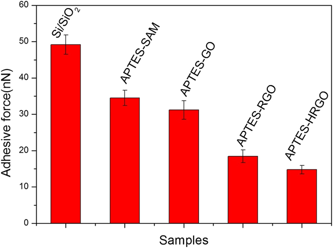
Initially, we measured the adhesive force of the samples in air. As shown in Fig. 4, the strongest adhesion (49.2 nN) was observed between Si/SiO2 and AFM tip. Once APTES was grafted on the substrate, the adhesive force decreased to 34.5 nN. APTES-GO film has a similar adhesive force (31.2 nN). After reduction of APTES-GO, both APTES-RGO film (15.4 nN) and APTES-HRGO film (14.8 nN) have weaker adhesion. These results are consistent with WCA measurements, indicating adhesion is related to the wettability of the surfaces.
Adhesive forces for different samples in air.
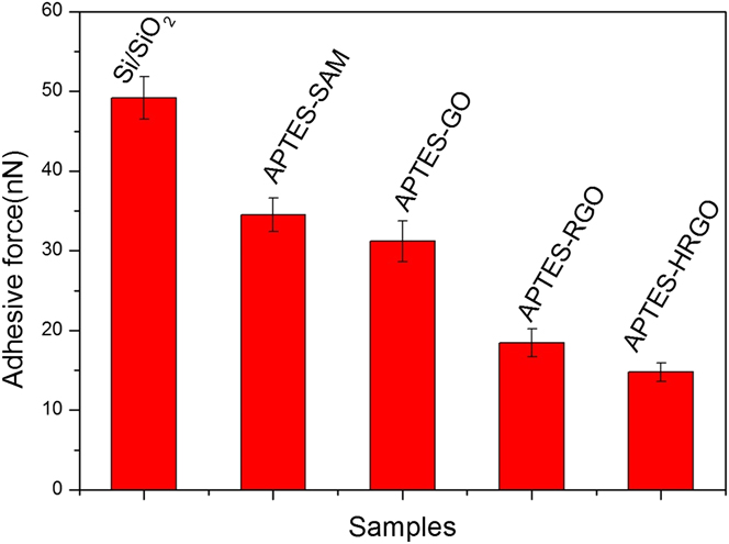
The Maugis–Dugdale theory was used to convert the measured adhesion force to the adhesion energy. Adhesion energies of those films to AFM tips are obtained as 0.57 J/m2 for APTES-HRGO, 0.54 J/m2 for APTES-RGO, 0.62 J/m2 for APTES-GO, and 0.75 J/m2 for APTES-SAM, respectively. The adhesion measurements are consistent and repeatable, with a maximum fluctuation of 10% over all the measured data. In fact, adhesive forces and adhesion energy values of those films in air are closely related to hydrophilicity of the surface—roughly decreases with hydrophobicity of surfaces. Thus, adhesion of Si substrates can be significantly suppressed by forming hydrophilic surfaces like APTES-RGO film and APTES-HRGO film.
The adhesive forces between samples and AFM tips are believed to be the sum of capillary force (F cap), van der Waals force (F vdW), electrostatic force (F e), and chemical bond force (F c). Reference Xiao and Qian36 Therefore the adhesive force can be expressed as
 $${F_{{\rm{ad}}}} = {F_{{\rm{cap}}}} + {F_{{\rm{vdW}}}} + {F_{\rm{e}}} + {F_{\rm{c}}}\quad .$$
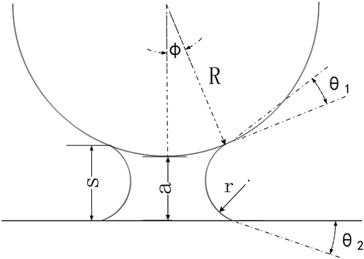
For an idealized meniscus geometry (Fig. 5) formed between a single asperity sphere tip of radius R and a plane surface with a separation a in ambient condition, capillary force can be estimated as the sum of capillary pressure and surface tension. Reference Xiao and Qian36
 $${F_{{\rm{cap}}}} = {F_{\rm{P}}} + {F_{\rm{S}}} =\; \pi \gamma R\left( { - \sin \phi + {{\cos \left( {{\theta _1} + \phi } \right) + \cos \,{\theta _2}} \over {{a \over R} + 1 - \cos \,\phi }}} \right) + 2\pi \gamma R\,\sin \,\phi \,\sin \left( {{\theta _1} + \phi } \right)\quad .$$
Where γ is the surface tension of the liquid, θ1 and θ2 are the contact angles of the liquid with AFM tip and samples, respectively, and 2ϕ is the central angle corresponding to meniscus. The maximum capillary force can be calculated at a = 0. It is assumed that ϕ is equal to zero, which is plausible since the radius of AFM tip is far greater than the curvature radius meniscus. Thus taking a = 0 and ϕ → 0, Eq. (3) can be reduced to:
 $${F_{{\rm{cap}}}} = 2\pi \gamma R\left( {\cos \,{\theta _1} + \cos \,{\theta _2}} \right)\quad .$$
Schematic of ideal meniscus formed between a spherical tip and a flat surface.

Taking γ = 72.8 mN/m and θ1 = 60°, Reference Ito, Namba, Buhlmann and Umezawa37 the values of the capillary forces are 13.7 nN, 10.0 nN, 8.98 nN, 4.02 nN, and 3.40 nN, for Si substrate, APTES-SAM, APTES-GO, APTES-RGO, and APTES-HRGO, respectively. These results are much less than the adhesive forces we measured, which is mainly attributed to the inaccurate assumptions and the highly complexity of meniscus structure. In real contact, both the spherical tip and plane have many asperities, due to roughness of the tip, folding of graphene sheets and water or other contaminations absorbed onto the surface of the tip and the sample surface, so the capillary force should be the sum of all meniscus forces, in which case the diameter of the asperity and the separation a are of the same order of magnitude and the term a/R cannot be ignored. The roughness of the two surfaces, the size of water meniscus and other parameters that influence capillary forces are also supposed to be considered to calculate the value. Further studies are still needed to perfect this model to make the calculated value more approximate to the real.
The van der Waals force can be estimated by the following Eq. (5) Reference Xiao and Qian36
 $${F_{{\rm{vdW}}}} = \;F_{{\rm{vdW}}}^{{\rm{water}}}\left\{ {1 - {1 \over {{{\left[ {1 + R\left( {1 - \cos \,\phi } \right)/a} \right]}^2}}}} \right\} + F_{{\rm{vdW}}}^{{\rm{air}}}\left\{ {{1 \over {{{\left[ {1 + R\left( {1 - \cos \phi } \right)/a} \right]}^2}}}} \right\}\quad .$$
Where
 $F_{{\rm{vdW}}}^{{\rm{water}}}$
and
 $F_{{\rm{vdW}}}^{{\rm{air}}}$
are the van der Waals forces between samples and AFM tip when the medium is water and air, respectively. Equation (5) can estimate the van der Waals force when the humidity value varies from 0% to 100%. For a rough approximation we just use
 $F_{{\rm{vdW}}}^{{\rm{water}}}$
and
 $F_{{\rm{vdW}}}^{{\rm{air}}}$
as the final value of van der Waals forces in water and in air, which can be given as
 $${F_{{\rm{vdW}}}} = {{AR} \over {6{a^2}}}\quad .$$
Where a and R are the same as in Eqs. (3) and (4). A is the material specific Hamaker constant and is normally in the range of 10−19 J. Reference Hamaker38 Precise quantifications of van der Waals forces were not conducted since we did not obtain the Hamaker coefficients of the samples. Nevertheless, rough estimate indicates that van der Waals forces are much smaller than capillary forces. According to Hamaker’s calculation, Reference Robinson, Kay and Kolosov23,Reference Noskov, Scherer and Maskos39 when the gap between the AFM tip and sample surfaces is filled with liquid, the combined Hamaker constant diminishes. Namely, the van der Waals force under the liquid condition is usually smaller than that in air. Thus, the adhesive forces in liquid condition should be smaller than that in air condition.
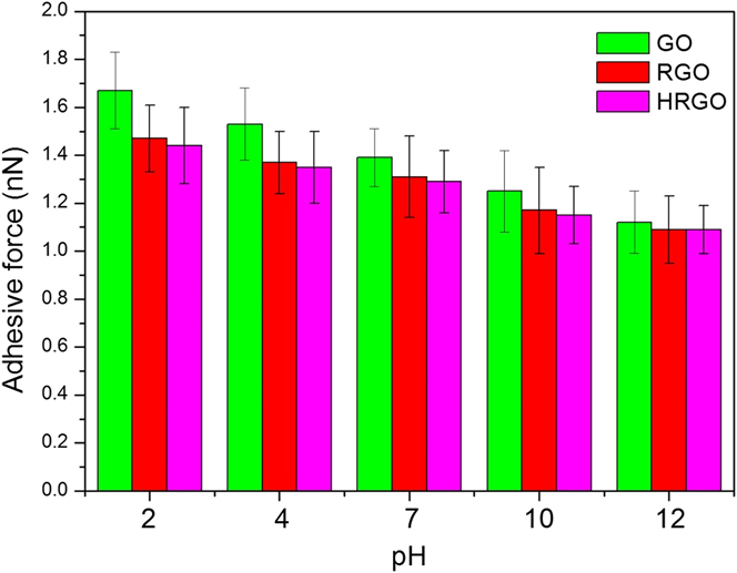
Figure 6 shows the adhesive forces measured under different pH conditions. Standard deviations are caused by variations in measurements from location to location. However, the general pH behavior was repeatable for each pH value. Apparently these values are several times lower than those measured in air, which is mainly due to the disappearance of the capillary force. As previously discussed, the dramatic decrease of van der Waals force is also partially responsible for this phenomenon. Note that all the measured values of three samples decrease with the pH value increasing from 2 to 12, and this variation is more noticeable in APTES-GO film. The pH-dependent behavior of adhesion data for APTES-RGO film is almost the same as that of APTES-HRGO film.
Adhesive forces for three graphene films at different pHs.

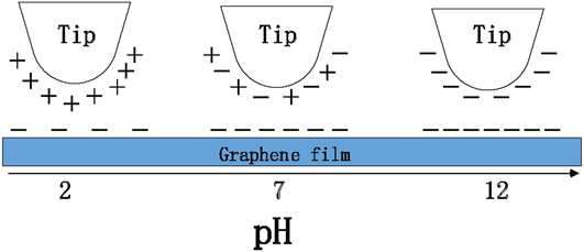
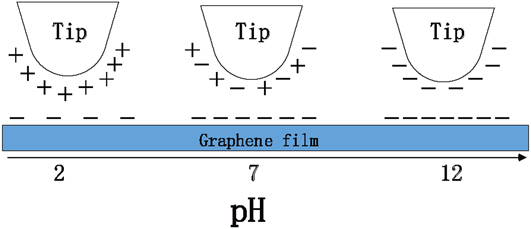
Due to the disappearance of the capillary force, the adhesive force in liquid environment is composed of van der Waals, electrostatic, and chemical bond forces. The diversity of adhesive forces at different pH conditions is largely ascribed to electrostatic forces, as van der Waals and chemical bond forces rarely vary in this situation. Before further discussion, a renewed understanding of the complex composition of silicon nitride surfaces is needed. A silicon nitride ceramic in water in fact undergoes a sequence of hydrolysis reactions. Therefore the surface of the AFM tip has a relatively thin layer predominantly composed of silicon dioxide, amphoteric silanol, and basic silylamine groups. Reference Senden and Drummond40,Reference Tsukruk and Bliznyuk41 As silicon nitride possesses a zwitterionic surface, it can demonstrate positive or negative behavior by shifts of equilibria of different types of surface groups. At very low pH values, the silicon nitride surfaces are positively charged, and change from positive to neutral at pH = 5–6. Between pH 6 and pH 8.5 they are slightly net negative, and become increasingly negative at higher pH levels. Reference Senden and Drummond40,Reference Tsukruk and Bliznyuk41 Meanwhile the oxygen-containing functional groups on APTES-GO film can be donators or acceptors of protons in response to the environmental change in pH value. At low pH values, APTES-GO films are slightly negative due to the protonation of the ionizable groups (carboxylic or hydroxyl group) on GO. While in highly alkaline media, these groups are deprotonated and APTES-GO film becomes strongly negatively charged. Reference Hu, Yu, Hou, Zhou and Song42 An illustration of tip-surface electrostatic interactions at different pH values is presented in Fig. 7. At very low pH values, positively charged silicon nitride tip attracts negatively charged APTES-GO film resulting in an increase of adhesive force. With the increase of pH value, this electrostatic attraction becomes weaker and vanishes at intermediate pH levels. Within this pH range, the tip surface is virtually neutral and only the van der Waals and chemical bond forces contributes to adhesion. When pH values exceed 8.5, strong repulsive interaction between two highly negative charged surfaces partly opposes van der Waals force, resulting in a decrease in adhesive force. Compared with APTES-GO film, fewer oxygenic functional groups on APTES-RGO film or APTES-HRGO film make their adhesion less sensitive to the pH environment.
A scheme of tip/surface pairs with different surface charge distributions and force balances at different pH values.
C. Friction measurements
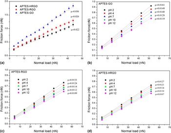
The nanoscale friction forces of APTES-GO film, APTES-RGO film, and APTES-HRGO film in air and in liquid are shown in Fig. 8. Obviously, their loading curves (friction forces versus applied load) can be fitted well by straight lines, that is, obeying Amonton’s Law
 $${F_{\rm{f}}} = \mu {F_{\rm{n}}} + {F_0}\quad .$$
Where F f is the friction force, F n is the normal load, μ is the friction coefficient defined as μ = ∂F f/∂F n, and F 0 is the intercept denoting the friction force at an external load of zero. Reference Foster, Alexander, Leggett and McAlpine43,Reference Brewer, Beake and Leggett44
Friction force versus load force for (a) three graphene films in air, (b) APTES-GO film, (c) APTES-RGO film, and (d) APTES-HRGO film at different pH values.

It is clearly seen from Fig. 8(a) that APTES-HRGO film has the lowest coefficient of all measured samples in ambient conditions, while APTES-GO film has the highest. This result is quite similar to the adhesive force measurements. Hydrophilic surfaces with high adhesion have poor lubricities, while hydrophobic surfaces with low adhesive forces exhibit better performance. It is worth noting that the observed differences are chiefly related to the microstructure and surface properties of samples and tips. It is reasonably assumed that the capillary menisci in contact area can build up at this low velocity. Reference Peng, Wang and Li45 Thus the adhesion between films and tips determined by surface structures and chemical compositions under the given ambient circumstances is the dominant contributor to nanoscale friction. As capillary force is the major part of adhesive force in air, improving surface hydrophobicity is an effective way to vastly lower friction of graphene films.
The measured friction forces of three types of graphene films in aqueous solutions at selected pH values as a function of applied load were depicted in Figs. 8(b)–8(d). Typical standard deviations arising from variations of measurements from location to location were basically found to be 10% of the data point value. Clearly the values measured in solutions were much lower than those measured in air, as would have been expected, because of the low adhesion in aqueous environments resulting from the absence of capillary forces. The pH-dependent friction behaviors of these graphene films, exhibiting high friction forces in acidic and air environments, can be illustrated by the puckering effect model. When a stiff tip slides over atomically thin graphene films, adhesions and external loads can generate out-of-plane deformation of a graphene sheet, causing larger contact area and increasing friction. Reference Lee, Li, Kalb, Liu, Berger, Carpick and Hone46,Reference Li, Lee, Carpick and Hone47
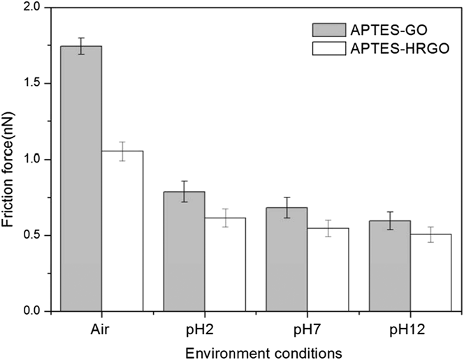
However, the puckering effect is suppressed when pH value increases as shown in Fig. 9. On one hand, tip-sample adhesive force decreases with the increase of pH values. On the other hand, the quantity of deprotonated oxygen atoms on GO rises in alkaline solution, which can form strong hydrogen bond with unreacted APTES and thus result in strong combination of film and substrate. For the above two reasons, the friction force results decrease with the increase of pH value for both APTES-GO and APTES-HRGO films (seen in Fig. 9).
Friction forces under 40 nN of hydrophilic surface (APTES-GO film) and hydrophobic surface (APTES-HRGO film) at different environment conditions.

It should be noted that the pH-dependent friction performances of surfaces between APTES-GO and APTES-HRGO films have less noticeable distinction compared with those in air (Fig. 9), indicating that surface wettability and adhesive forces have little influence on friction forces in aqueous solutions. Among all three films, APTES-HRGO film has the best lubricity, whether in air or in liquids with different pH values, which can be attributed to fewer structural defects and oxygenic groups on graphene sheet. Reference Wang, Zhi and Mullen21
IV. CONCLUSIONS
In this work, APTES-GO films were prepared by covalently grafting GO to silicon substrates, and then thermally or hydrothermally reduced to obtain APTES-RGO film and APTES-HRGO film, respectively. Their microstructures and nanoscale tribological behavior were investigated. Results indicated that capillary force is the main contributor to adhesive forces in air. Hydrophobic surfaces have smaller adhesive forces compared with hydrophilic surfaces, as capillary forces decrease sharply with decreasing wettability. Due to the disappearance of capillary forces and the reduction of van der Waals forces, adhesive force and friction force under the same load in liquid are much less than in air. The observed adhesive forces in aqueous solutions slightly decrease with the increase of pH values, which can be explained by the electrostatic interaction between the silicon nitride tip and graphene films. The negatively charged oxygenous groups on graphene films in aqueous solution can attract or repel zwitterionic silicon nitride tip with the pH changing from acid to alkaline. Friction coefficients of the three types of graphene films also reduced slightly with the increasing pH values. As the puckering effect that is usually produced on a weak adherent substrate are suppressed here due to enhancement of bonding strength between films and substrates, tribological resistances of graphene films in high pH conditions are smaller to those in low pH conditions. Among the three types of graphene films, APTES-HRGO film possesses the best tribological performance, which will have promising applications in MEMS, rechargeable batteries, sensors, biomedical devices, and so on.
ACKNOWLEDGMENT
The authors would like to thank the National Natural Science Foundation of China (51575341) and the Opening Fund of State Key Laboratory of Solid Lubrication, Lanzhou Institute of Chemical Physics, Chinese Academy of Sciences (Contract No. 1103) for financial support. We are also grateful to the Instrumental Analysis Center of Shanghai Jiao Tong University for providing technical assistance.