I. INTRODUCTION
Polarization-agile antennas, whose polarization state can be switched electronically, are attracting more attention for use in modern wireless communication systems because of their potential to improve the performance of wireless communications. This type of antenna combines pairs of orthogonal polarizations, for example, horizontal/vertical, ±slant 45°, or left-hand/right-hand circular polarization (RHCP/LHCP), which offer various polarizations for the same frequency. Polarization-agile antennas are useful for many other applications. For example, it can be used to select best communications channel in real-time to improve the communication quality because a mobile handset may be rotated and results in polarization mismatch [Reference Landon and Furse1]. In [Reference Fujimoto and James2], it has been shown that antennas with polarization diversity are highly effective in eliminating multipath fading caused by reflected signals in complex environments, and circularly polarized systems have been demonstrated to offer many advantages over linearly polarized systems, which can significantly mitigate multipath fading from indoor environments [Reference Kajiwara3]. In addition, polarization-agile antennas can also realize frequency reuse based on orthogonal polarization states. It can also provide polarization modulation scheme used in active read/write the microwave tagging system [Reference Kossel, Küng, Benedickter and Bächtold4].
Several antenna structures offering polarization-agile characteristics have been proposed in the literature [Reference Jang, Kim, Sung and Kim5–Reference Ferrero, Luxey, Staraj, Jacquemod, Yedlin and Fusco17]. A popular method used to switch antenna polarization is the use of PIN diodes to reconfigure the antenna structure. This requires a DC bias to control the switching of the ON/OFF state of the diode by changing the electric characteristic of perturbation segments through the diodes. Dual polarizations switchable antennas using diodes embedded on the antenna element have been proposed [Reference Jang, Kim, Sung and Kim5–Reference Yoon, Baik, Lee, Pyo, Han and Kim11], and a single-pole double-throw switch circuit is combined in the antenna design to achieve a high-speed switching capability [Reference Feng, Nishiyama and Aikawa12–Reference Ushijima, Feng, Nishiyama and Aikawa13]. These antenna designs perform well in the design frequency band. However, the use of diodes complicates the antenna structure and DC-bias network. It does not perform well when applied to high-frequency applications where the antenna dimension is relatively small and no lumped PIN diode is available. Furthermore, the switching signal traces raise the complexity of the overall antenna layout, and the baseband traces may influence the antenna performance. In addition, only a few microstrip antenna designs found in the literature possess switchable quadrature polarization characteristics. In [Reference Schaubert, Farrar, Sindoris and Hayes14], the first design possess full polarization reconfigurability was presented. The antenna is able to switch between two orthogonal linear and two CPs by proper location of the shorting posts. However, it requires embedding microwave switching diodes for the shorting posts and the complex biasing network, which makes the design difficult in realization. In [Reference Haskins, Hall and Dahele15], polarization-agile active patch antenna was developed using two transistors. The radiation can be selected to be circularly polarized in either sense, or linearly polarized in the vertical, horizontal, or either diagonal plane. In [Reference Wu, Wu, Lai and Chen16, Reference Ferrero, Luxey, Staraj, Jacquemod, Yedlin and Fusco17], other approaches were proposed for quadri-polarization diversity using diodes and varactors, respectively, to change its polarization state. In [Reference Ludlow and Fusco18], a four port polarization-agile antenna using open-ended waveguide was presented, which can also provide quadri-polarization. However, the four inputs need to be assigned with different phase combination, which needs four additional phase shifters. This paper proposes a novel eight-port feeding network with four inputs and four outputs, which is designed to produce a via-free quadri-polarization-switchable microstrip antenna. This feeding network generates different phase combinations of the output ports based on the input ports selected by the user. By properly combining the feeding network with the patch-radiating element, four polarizations of the antenna can be generated. Combined with the proposed feeding network, the first design uses two adjacent square patch resonators to excite two orthogonal pairs of polarizations, including horizontal/vertical and RHCP/LHCP . The planar and single-layer characteristics enable applying this design to high-frequency applications. In the second design, four CP patch antenna are introduced to improve the axial-ratio bandwidth. In these four CP patches, two are RHCP and two are LHCP, which form a sequentially rotated array. This design can also be used to synthesize these four polarizations, and effectively improves CP performance.
When integrating with a single-pole four-throw radio frequency switch, the proposed design can be configured as a quadri-polarization-agile antenna. The proposed two topologies separate the active switching circuit and the passive antenna part, reducing the complexity of routing the switching signal traces and lowering the influence of the baseband circuit, making it more suitable for integration with microwave circuits and use with high-frequency applications.
II. QUADRI-POLARIZED ANTENNA DESIGN USING TWO SQUARE PATCH RESONATORS
A) Operating mechanism
Figure 1 shows the schematic of the proposed quadric-polarization antenna. The proposed design can generate two orthogonal pairs of polarization, that is, vertical polarization, horizontal polarization, or RHCP and LHCP, respectively. The two orthogonally paired CPs are contributed by square patches A and B, respectively. As the feeding network is fed from Port 1, the input power is equally divided to output Ports 5 and 6 with a 90° phase difference; thus, RHCP is generated by square patch A, and no power flows into square patch B. In the same manner, as the antenna is fed from input Port 4, the input power is equally divided to output Ports 7 and 8 with a 90° phase difference; thus, LHCP can be generated, and no power flows to square patch A. The orthogonal pair of linear polarizations (LP) can be generated by combining RHCP and LHCP using the two square patches. For example, when choosing input Port 2, both square patches A and B are driven with equal power. In this case, square patch A generates LHCP, and square patch B generates RHCP. These orthogonal pairs of CP on square patches A and B have the same amplitude but a 90° phase difference; thus, the currents are in the same direction on the X-axis, but in the opposite direction on the Y-axis. A linearly polarized beam along the X-axis and traveling in the positive Z-direction can then be synthesized. Furthermore, when choosing input Port 3, both square patches A and B are driven with equal power where square patch A generates LHCP and B generates RHCP. In this case, the phase in square patch B is 90° in advance. Thus, the currents are in the same direction on the Y-axis but in opposite directions on the X-axis. A linearly polarized beam along the Y-axis and traveling in the positive Z-direction can then be synthesized.
Structure of the proposed four-port microstrip quadri-polarization diversity antenna.

B) Feeding network
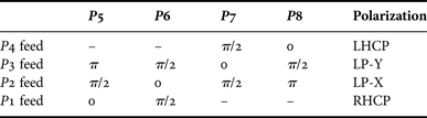
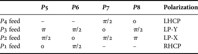
The proposed antenna is designed for use at 3.5 GHz. The antenna is printed on a 0.8-mm-thick FR4 substrate, which has a relative permittivity of 4.4 and a loss tangent of 0.02. This design consists of two adjacent square patches and a feeding network with four input ports. Corresponding to each input port, the feeding network generates different phase combinations of the output ports, and each phase combination can synthesize different polarizations. Thus, antenna polarization can be changed by switching to different inputs. The feeding network consists of three quadrature hybrids to provide a 90° phase difference. As Port 1 is fed and other input ports are terminated, the input power is equally divided to output Ports 5 and 6 with equal amplitude but with a 90° phase difference. No power is transmitted into output Ports 7 and 8, which are isolated. As the input port switches to Port 2 and other input ports are terminated, the input power splits equally to points F and G, but the phase at point G is 90° later than that at point F. In the same manner, the power at point F splits to points A and B, and the power at point G splits to points C and D. Finally, the four output ports have the same magnitude, and the achieved phase differences are 90°, 0°, 90°, and 180° with output Port 6 as the reference point. Table 1 shows the theoretical phase delay of output Ports 5, 6, 7, and 8.
Phase delay of each output ports.
The proposed quadri-polarization-agile antenna uses two or four patch elements to synthesize different polarizations, and in some cases, only parts of the patches are activated to transmit power. However, when the proposed antenna receives signals, each patch element is induced and polarized with the incoming electromagnetic wave; thus, the proposed antenna has a diversity gain, and the received signal does not output to only one port. The scattering matrix used to describe the relationship between inputs and outputs of the proposed feeding network is shown below:
 $$\left[{\matrix{ {P_{out} 1} \cr \vdots \cr {P_{out} 8} \cr } } \right]= \left[{\matrix{ {S_{11} } & \cdots & {S_{18} } \cr \vdots & \ddots & \vdots \cr {S_{81} } & \cdots & {S_{88} } \cr } } \right]\left[{\matrix{ {P_{in} 1} \cr \vdots \cr {P_{in} 8} \cr } } \right]\comma \; $$$$\left[\matrix{ {P1} \cr {P2} \cr {P3} \cr {P4} \cr {P5} \cr {P6} \cr {P7} \cr {P8}} \right] = \displaystyle{1 \over 2} \left[\matrix{ 0 &0 &0 &0 &{\sqrt 2 e^{j \theta}} &\sqrt{2} e^{j\left(\theta - \displaystyle{\pi \over 2} \right)} &0 &0 \cr 0 &0 &0 &0 &e^{j\left(\theta - \displaystyle{\pi \over 2} \right)} &e^{j\theta} &e^{j\left(\theta - \displaystyle{\pi \over 2} \right)} &e^{j\lpar \theta - \pi \rpar} \cr 0 &0 &0 &0 &e^{j\lpar \theta - \pi \rpar} &e^{j\left(\theta - \displaystyle{\pi \over 2} \right)} &e^{j\theta} &e^{j\left(\theta - \displaystyle{\pi \over 2} \right)} \cr 0 &0 &0 &0 &0 &0 &\sqrt{2} e^{j\left(\theta - \displaystyle{\pi \over 2} \right)} &\sqrt{2} e^{j\theta} \cr \sqrt{2} e^{j\theta } &e^{j\left(\theta - \displaystyle{\pi \over 2} \right)} &e^{j\lpar \theta - \pi \rpar} &0 &0 &0 &0 &0 \cr \sqrt{2} e^{j\left(\theta - \displaystyle{\pi \over 2} \right)} &e^{j\theta} &e^{j\left(\theta - \displaystyle{\pi \over 2} \right)} &0 &0 &0 &0 &0 \cr 0 &e^{j\left(\theta - \displaystyle{\pi \over 2} \right)} &e^{j\theta} &\sqrt{2} e^{j\left(\theta - \displaystyle{\pi \over 2} \right)} &0 &0 &0 &0 \cr 0 &e^{j\lpar \theta - \pi \rpar} &e^{j\left(\theta - \displaystyle{\pi \over 2} \right)} &\sqrt{2} e^{j\theta} &0 &0 &0 &0} \right] \cdot \left[\matrix{{P1} \cr {P2} \cr {P3} \cr {P4} \cr {P5} \cr {P6} \cr {P7} \cr {P8}} \right].$$
For example, when the incoming signal is linearly polarized along the X-axis, the induced current of the two adjacent patches flow into Ports 5 and 7; the input vector can be expressed as
 $$\left[{\matrix{ 0 &0 &0 &0 &{e^{j\theta } } &0 &{e^{j\theta } } &0 \cr } } \right]^{\rm T} .$$
By substituting this input vector into (2) and multiplying with the scattering matrix of the feeding network, the output vector would be
 $$\left[{\matrix{ {\displaystyle{1 \over {\sqrt 2 }}e^{j\theta } } &{e^{j\left({\theta - \displaystyle{\pi \over 2}} \right)} } &0 &{\displaystyle{1 \over {\sqrt 2 }}e^{j\left({\theta - \displaystyle{\pi \over 2}} \right)} } &0 &0 &0 &0 \cr } } \right]^{\rm T} .$$
In this vector, the values of Ports 1 and 4 are the diversity gain of the proposed antenna when receiving an X-directed linearly polarized signal. Similarly, when the incoming wave is LHCP toward a negative Z-axis, the input vector can be expressed as
 $$\left[{\matrix{ 0 &0 &0 &0 &{\displaystyle{1 \over {\sqrt 2 }}e^{j\theta } } &{\displaystyle{1 \over {\sqrt 2 }}e^{j\left({\theta - \displaystyle{\pi \over 2}} \right)} } &{\displaystyle{1 \over {\sqrt 2 }}e^{j\theta } } &{\displaystyle{1 \over {\sqrt 2 }}e^{j\left({\theta - \displaystyle{\pi \over 2}} \right)} } \cr } } \right]^{\rm T} .$$
By substituting this input vector into (2) and multiplying it with the scattering matrix of the feeding network, the output vector would be
 $$\left[{\matrix{ 0 &{\displaystyle{1 \over {\sqrt 2 }}e^{j\left({\theta - \displaystyle{\pi \over 2}} \right)} } &{\displaystyle{1 \over {\sqrt 2 }}e^{j\lpar {\theta - \pi } \rpar } } &{e^{j\left({\theta - \displaystyle{\pi \over 2}} \right)} } &0 &0 &0 &0 \cr } } \right]^{\rm T} .$$
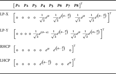
In this vector, P4 is the output of the receiving signal, and the values of Ports 2 and 3 are the diversity gain of the proposed antenna. Table 2 list outputs of the incoming signal of four types of polarization.
Outputs of the incoming signal of four types of polarization.
C) Simulation and experimental results
The proposed design was simulated using the full-wave simulator, Ansoft's HFSS, and a prototype was fabricated to verify the simulation, which is shown in Fig. 2. Figure 3 shows the measured and simulated reflection coefficients of the proposed four-port quadri-polarization antenna. As shown in Fig. 3, each input is well matched around the operating band, and the reflection coefficients of the four input ports are better than –10 dB, which starts from 3.15 to 3.9 GHz. The coupling between each input port was also evaluated. Figure 4 shows the measured isolation between each input port when the antenna is fed from Ports 1 and 2 (results when fed from Ports 3 and 4 are not shown here due to the symmetry). It shows that the four input ports have good isolation where most of the input power is delivered to the antenna elements around the design band. Figure 5 shows the measured and simulated axial ratio of the proposed antenna when it is fed from Port 1 where RHCP is generated. The measured and simulated boresight gain of the antenna is also plotted in Fig. 5. The simulation result shows the achieved bandwidth where the axial ratio lower than 3 dB is approximately 3.11% from 3.48 to 3.59 GHz. Figure 6 shows the measured and simulated radiation patterns in the X–Z-plane as the antenna operates in RHCP mode at 3.5 GHz. The achieved peak gain is approximately 0.41 dBic. Figure 7 shows the linearly polarized radiation pattern on the X–Z-plane as the antenna fed from Port 2; the antenna peak gain achieved at broadside is approximately 1.146 dBi. A small cross-pol radiation pattern, which is 15 dBi lower than the co-polarization radiation pattern at broadside, shows the purity of the synthesized linear polarization. Because the antenna structure is symmetric, simulation results show that the antenna generates a linear polarization in the Y-direction and LHCP when it is fed in Ports 3 and 4 (not shown here). As shown in Fig. 5, the achieved axial ratio bandwidth is approximately 3.26% for RHCP and LHCP, which is restricted mainly by the physical limitation of the patch antenna. Thus, a novel four-element quadri-polarization antenna is proposed to enhance the axial ratio bandwidth of the proposed design.
Fabricated prototype of the proposed four-port microstrip quadri-polarization diversity antenna.
Measured and simulated reflection coefficients of each input ports.
Measured isolation between each input ports when the antenna fed from (a) port 1 and (b) port 2.
Measured and simulated axial-ratio and boresight gain of the proposed antenna.
Measured and simulated CP radiation pattern as the antenna fed from Port 1.
Measured and simulated LP radiation pattern as the antenna fed from Port 2.
III. QUADRI-POLARIZED ANTENNA DESIGN USING FOUR CIRCULARLY POLARIZED PATCH RESONATORS
A) Operating mechanism
Figure 8 shows the proposed four-element quadri-polarization antenna. The corners of the four rectangular patches are accurately cut to obtain a CP at the element level, and the four CP patches are connected to each output port of the feeding network. The benefit of the proposed feeding network is that the output of each port has a relative phase difference of 90°. Thus, a two-element sequential rotation technique can be applied to improve the axial ratio bandwidth. The physical orientations of circular patches and their feeding positions are determined based on the output phases of the feeding network and the sequential rotation design rule. In this design, the upper two patches connected to output Ports 5 and 8 are a set of a two-element sequentially rotated array, and these two radiating elements are RHCP patches. In addition, the lower two patches connected to output Ports 6 and 7 are another set of two-element sequentially rotated arrays, and the two radiating elements are LHCP patches. This configuration makes the proposed antenna achieve a wide axial ratio bandwidth and is able to synthesize a pair of orthogonally LP and a pair of orthogonal CPs by switching input ports. Figure 9 shows the configurations of the four patches and the current direction with respect to phases.
(a) Structure of the proposed quad-element microstrip quadri-polarization diversity antenna, (b) side view.
Antenna configuration and the operating mechanism of the proposed four-element quadri-polarization diversity antenna.
As the feeding network was fed from Port 1, only circular patches A and C were activated. The polarizations of patches A and C were RHCP and LHCP, respectively, and the two patches had a phase difference of 90°; thus, the current of these two patches was in the same direction along the X-axis, but in the opposite direction along the Y-axis. After this process, a beam linearly polarized along the X-axis and traveling in the positive Z-direction can be synthesized. Similarly, as the feeding network was fed from Port 4, only circular patches B and D were activated. As before, the polarizations of patches B and D were RHCP and LHCP, and these two patches had a phase difference of 90°. Because the physical orientation of both patches B and D were 90° rotated with respect to patches A and C, the current of these two patches was in the same direction along the Y-axis, but was in the opposite direction along the X-axis. Thus, a linearly polarized beam along the Y-axis and traveling in the positive Z-direction can then be synthesized.
To generate CP, as the feeding network is fed from Port 2, all the CP patches are activated. Because the feeding network provides a phase delay of 90, 0, 90, and 180° to patches A, C, D, and B, respectively, the upper two RHCP patches form a two-element sequentially rotated array. In this case, the far-field radiation of the lower two LHCP patches, in which the current distributions are in the opposite directions, canceled each other. Therefore, RHCP with an improved axial-ratio bandwidth traveling in the positive Z-direction can then be generated. Furthermore, when the feeding network was fed from Port 3, all CP patches were activated; however, in this case, the feeding network provides a phase delay of 180, 90, 0, and 90° to patches A, C, D, and B, respectively. The lower two LHCP patches B and D form a two-element sequentially rotated array, and the far-field radiation of the upper two RHCP patches A and C, with the current distribution in the opposite direction, is canceled. Thus, LHCP with an improved axial ratio bandwidth traveling in the positive Z-direction can then be generated.
For receiving the signal, this design also provides a diversity gain. Table 3 shows the corresponding input vectors of the four types of polarized incoming singles. For receiving a linear polarized signal, because the four patches are CP, the induced power on each patch is halved. For receiving the RHCP signal, because the upper two patches (A and B) were orthogonal to the incoming wave (polarization mismatch), there was no induced power on these two patches. In addition, when receiving the LHCP signal, the lower two patches (C and D) were orthogonal to the incoming wave; thus, there was no induced power on these two patches. By substituting the vectors in Table 3 to (2), the output of each type of polarized signal can be obtained (Table 4).
Input vector of the incoming signal of four types of polarization.
Outputs of the incoming signal of four types of polarization.
B) Simulation and experimental results
Figure 10 shows a photograph of the fabricated prototype of the quadri-polarization antenna with four CP patches. This design was fabricated on an FR4 substrate with a dielectric constant of 4.4 and a loss tangent of 0.02. The circuit board is composed of the following three layers: radiating patches, a ground plane, and feeding networks. The thickness of the substrates between each layer is 0.8 mm. Four traces connecting output ports of the feeding network to each patch element has the same electrical length, and all vias have a diameter of 0.54 mm. Figure 11 shows the measured and simulated reflection coefficients of the prototype design, of which the simulation was performed by Ansoft's HFSS [19] and the measurement was performed by using an agilent vector network analyzer E8364B. The measured results are in good agreement with the simulation. The achieved impedance bandwidth is approximately 19.7%. Figure 12 shows the measured isolation between each input port when the antenna is fed from Ports 1, 2, 3, and 4. Figure 13 shows the measured and simulated axial ratio bandwidth of RHCP and LHCP, which was found when the antenna was fed from Ports 2 and 3. The achieved 28.6% axial ratio bandwidth of LHCP and 22.8% axial ratio bandwidth of RHCP have been greatly improved compared with the previous design. Figures 14–17 show the measured and simulated radiation patterns in the Y–Z-plane of RHCP, LHCP, and LP in the X-direction, and LP in the Y-direction at 3.5 GHz. The measured and simulated boresight gain of the antenna is plotted in Fig. 18. The measured peak gain is approximately 0.91 dBic for CP and 0.53 dBi for LP. The small cross-pol radiation pattern, which is 15 dBi lower than the co-polarization radiation pattern at broadside, shows the purity of the synthesized polarization. Because the proposed design switches antenna polarization by using different inputs, some input power is canceled in the far-field to synthesize the four polarizations. Therefore, it lowers the achieved antenna gain. The back radiation of Ports 1 and 3 are smaller than Ports 2 and 4 due to their better synthesized polarization purity. The experiments reveal switchable quadri-polarization characteristics and improved axial ratio bandwidth of CP modes of the proposed design.
Fabricated prototype of the proposed quad-element microstrip quadri-polarization diversity antenna: (a) top view, (b) bottom view.
Measured and simulated reflection coefficients of each input ports.
Measured isolation between each input ports of the second design when the antenna fed from (a) Port 1, (b) Port 2, (c) Port 3, and (d) port 4.
Measured and simulated axial-ratio of the proposed antenna as it operates in RHCP and LHCP modes.
Measured and simulated LP radiation pattern as the antenna fed from Port 1.
Measured and simulated CP radiation pattern as the antenna fed from port 2.
Measured and simulated CP radiation pattern as the antenna fed from Port 3.
Measured and simulated LP radiation pattern as the antenna fed from Port 4.
Measured and simulated boresight gain of the proposed antenna.
IV. CONCLUSION
This paper presented the designs and models of two novel planar quadri-polarization antennas. The new feeding network with four inputs is designed to provide quadri-polairzation switching capability. The first antenna design comprises two adjacent square patch antennas where four antenna polarizations (X-polarized LP, Y-polarized LP, RHCP, and LHCP) can be generated and synthesized. The single-layer and via-free topology makes this antenna suitable for high-frequency applications. In the second antenna design, four CP elements applying the sequential rotation technique are presented, and they effectively improved the axial ratio bandwidth. For both designs, measured and simulated results such as the reflection coefficient, insertion loss, axial ratio, and radiation patterns, are presented to validate the proposed concept. By selecting different input ports, the polarization of the proposed antenna can be switched. The proposed two designs do not embed diodes, varactors, transistors, and active biasing circuits. Those designs separate the active switching circuit and the passive antenna part to reduce the design complexity, which makes them more applicable to various high-frequency applications. Both simulated and measurement results are presented and discussed to successfully validate our proposed designs.
Yu-Jen Chi (S'98) was born in Taipei, Taiwan, Republic of China(R.O.C.), in 1985. He received his B.S. and M.S. degrees in Electronic Engineering from National Ilan University, I-Lan, Taiwan, R.O.C., in 2007 and 2009, respectively, and the Ph.D. degree in Electrical Engineering from National Chiao Tung University, Hsinchu, Taiwan, R.O.C., in 2014. After graduation, he joined as faculty at Tamkang University, New Taipei City, Taiwan, in 2014, where he is currently an Assistant Professor of Electrical and Computer Engineering. His main research interests are in multiband antennas for mobile devices, CRLH leaky wave antennas, millimeter-wave antennas, metamaterials, and antennas for biomedical applications. Dr. Chi was the recipient of the Best Poster Award in the 2009 IEEE International Workshop on Antenna Technology (iWAT 2009).
Fu-Chiarng Chen received his B.S. and M.S. degrees from the National Taiwan University, Taipei, Taiwan, R.O.C., in 1988 and 1990, respectively, and the Ph.D. degree from the University of Illinois at Urbana-Champaign, Illinois, USA, in 1998, all in electrical engineering.
In 1998, he joined the Qualcomm Incorporated, San Diego, CA, USA. From 2003 to 2007, he was an Assistant Professor with the Department of Electrical Engineering, National Chiao Tung University, Hsinchu, Taiwan, where he is now an Associate Professor. His research interests include the experimental and computational aspects of applied electromagnetics, antennas, radars, inverse scattering, and RF/Microwave engineering for wireless communications. Dr. Chen holds eight US patents. Dr. Chen won the First Place Prize in the 1998 IEEE Antennas and Propagation Society International Symposium Student Paper Competition. He received the Macronix Young Chair Professorship Award in 2005, the National Chiao Tung University Outstanding Researchers Award in 2007 and 2008, the National Chiao Tung University Excellent Teaching Award in 2008, the National Chiao Tung University Electrical and Computer Engineering College Excellent Teaching Award in 2011 and 2012, and the National Chiao Tung University Excellent Mentoring Award in 2008 and 2011.