



Introduction
Antennas have attracted significant attention across various fields due to their compact size, uncomplicated design, passive wireless functionality, and capacity to handle both communication and detection tasks with minimal components [Reference Huang and Chen1]. Consequently, a diverse range of antennas has emerged for applications in communication, sensing, and biomedical domains [Reference Tan, Wei, Chen, Luo, Wu, Li and Xiong2–Reference Thakur, Mishra, Soni and Rao9]. In modern wireless communication, circularly polarized (CP) antennas have particularly picked researchers’ interest due to their unique ability to mitigate Faraday rotation effects, polarization discrepancies, and multipath interference, resulting in enhanced performance [Reference Nguyen, Bui, Le, Pham, Nguyen, Nguyen and Le10]. In paper [Reference Deng, Lv and Feng11], a CP antenna was developed with a patch and ring design with 3-dB axial ratio bandwidth (3-dB ARBW) of 6.94%. Nonetheless, this antenna suffered from a limited impedance bandwidth (IBW) which became a considerable challenge for designers. Another approach utilized ground radiation techniques to reduce antenna size while maintaining a 3-dB ARBW of around 10.6%, yet it also struggled with narrow IBW [Reference Park, Qu and Kim12]. These findings underscore the formidable hurdles in creating CP antennas with broader IBWs. Although numerous methods have been proposed to minimize antenna dimensions, further research is necessary to design CP antennas featuring wide ARBW and IBW, along with a simple and compact structure.
Within the antenna field, there exists a need to enhance the 3-dB ARBW for circular polarization. Various attempts have been made in pursuit of this goal, including the utilization of microstrip patches [Reference Poordaraee, Oraizi, Khajevandi and Glazunov13], parasitic patches [Reference Ding, Gao, Yu, Qu and Zhang14–Reference Wu, Yin, Wang and Lian16], stacked patches, and thicker substrates [Reference Yang, Zhou, Yu and Li17, Reference Chung18]. While these structures have expanded the AR bandwidth, they have also introduced complexity and bulkiness. In another approach [Reference Liu, Yang and Pan19], a cross-slot-coupled metasurface (MTS) antenna was proposed, offering a wide circular polarization bandwidth but at the expense of increased antenna size. Other techniques, like placing a substrate above the radiating element, have also been explored, but these designs still grapple with size issues and mechanical fragility due to the incorporation of an air gap [Reference Cheng and Dong20, Reference Nguyen-Trong, Tran, Nguyen and Abbosh21]. To surmount these challenges and achieve a compact form factor with improved circular polarization, researchers have turned to MTSs. Previous studies have introduced single-layered MTS antenna designs [Reference Hussain, Tran and Lê22, Reference Liang, Ouyang and Yang23] that achieve a broad 3-dB ARBW.
Recently, the characteristics mode theory (CMT) has played a pivotal role in antenna design, providing valuable insights into antenna operation [Reference Rajanna, Rudramuni and Kandasamy24]. CMT was initially formulated by Garbacz [Reference Garbacz and Turpin25] and later refined by Harrington and Mautz [Reference Harrington and Mautz26] in the 1970s. Through characteristic mode analysis (CMA), a deeper understanding of antenna structure is attained, encompassing eigenvalues, associated current modes, and far-field radiation, facilitating the creation of wideband, low-profile CP antennas [Reference Lin and Chen27–Reference Cabedo-Fabres, Antonino-Daviu, Valero-Nogueira and Bataller29].
Recently, there are different types of MTS-based antennas have been proposed with the aim of high gain, low profile, and circular polarization; however, very few of these designs are able to accomplish all three of these goals at once [Reference Hussain, Tran and Lê22, Reference Suyan, Lal Lohar, Dhote and Solunke30–Reference Jwair and Elwi33]. This work aims to develop an innovative broadband CP antenna with a low profile and high gain for C-band applications. The proposed design features a hexagonal-shaped MTS layer with a slotted ground and utilizes CMA to achieve circular polarization and broadside radiation. The key contributions include a CP antenna design with a −10 dB return loss bandwidth of 84.3% and dual 3-dB ARBWs of 18.6% and 3.74%. The proposed work also implements a proper feeding system to excite desired modes and achieve a broader 3-dB ARBW and IBW. The manuscript is structured into six sections. In the “Proposed MTS design through CMA” section, the CMA approach for the hexagonal MTS is discussed and the application of CMA on the MTS layer with slotted ground is also discussed. The “Proposed MTS-based antenna design” section presents the antenna design with a ground slot and coplanar waveguide (CPW) feed. The “Experimental setup for measuring proposed antenna” section presents the experimental setup. The “Result and discussion” section presents the results and discussion, comparing simulated and measured data. The “Conclusion” section concludes the work, summarizing the findings.
Proposed MTS design through CMA
This section describes the stepwise evolution of a CP high-gain antenna using CMA. It is divided into three subsections: (1) CMA analysis on a 3 × 4 hexagonal MTS layer to evaluate its properties, (2) applying CMA to an MTS layer with a slotted ground, and (3) implementing CMA on an MTS with a modified ground to achieve circular polarization.
CMA of the 3 × 4 hexagonal-shaped MTS layer
CMA is an analysis that is modal (free of excitation) in nature and characteristic mode (CM) in any conducting structure is current mode which is numerically calculated for that particular structure [Reference Lin and Chu34]. These current modes are introduced as a set of orthogonal modes that spread out the far field and current induced in the structure depending on the size and shape of the conducting structure. Thus, in the case of a perfect electric conductor body, characteristic current can be defined as [Reference Lin and Chu34, Reference Sharma, Gangwar, Singh, Solanki, Rajpoot, Kanaujia, Singh and Lay-Ekuakille35]
 \begin{equation}J = {\mathop {\sum\nolimits_n}{C_n}.{J_n}}.\end{equation}
Here,  ${C_n}$ represents modal weighting coefficient (MWC) and
 ${J_n}\,$ represents characteristic current associated with a particular mode. For an excitation, MWC defines impact created by every single current mode in overall electromagnetic response and it is determined as [Reference Chang, Zhang and Li36]
 \begin{equation}\left| {{C_n}} \right| = \frac{1}{{\left| {1 + j{\lambda {_n}}} \right|}}*\left| {\smallint {J_n}*{E_i}dS} \right| = MS*\left| {{v_n}} \right|.\end{equation}
Here, MS represents modal significance,  ${\lambda _n}$ represents eigenvalue, and
 ${v_n}$ stands for modal excitation coefficient. MS reveals the amplitude of the characteristic currents and indicates the share of a particular mode in the whole radiation, MS is written as
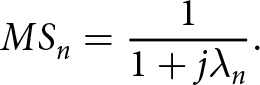 \begin{equation}M{S_n} = \frac{1}{{1 + j{\lambda _n}}}.\end{equation}
It must be noted that the mode is counted as a significant mode only if the MS of that particular mode is greater than 1/√2. Another significant criterion in the CMA is the characteristic angle (CA) that reveals difference in the phase of the real characteristic current ( ${J_n}$) and its characteristic field (
 ${E_n}$), which adds information about the behavior of every single mode. CA is determined as
 \begin{equation}C{A_n} = 180 - {\tan ^{ - 1}}\left( {{\lambda _n}} \right).\end{equation}
The aim is to design a single-layer MTS antenna with circular polarization using predefined rules in CMA. The rules are (1) simultaneously excite two orthogonal modes with current distributions perpendicular to each other. Modes in the context of CMT relate to particular patterns of voltages and currents on the structure. In terms of their current distributions, “orthogonal” modes refer to modes that are mutually perpendicular to one another. Consider the following scenario: the structure consists of two orthogonal modes, modes 1 and 2, each with a current distribution. Every mode has a distinctive current distribution of its own. When exciting two orthogonal modes, the current distributions associated with each mode are perpendicular to each other. (2) The magnitude of both modes at a specific point must be equal, MS1 = MS2, (3) maintain a 90° phase difference between these two modes, i.e., CA1 − CA2 = 90° [Reference Sharma, Gangwar, Singh, Solanki, Rajpoot, Kanaujia, Singh and Lay-Ekuakille35]. CAs refer to the angular distribution of the radiated electromagnetic fields linked to particular CMs of a radiating structure in CMT. The structure’s geometry and the modes that are being considered are used to define the CA. Certain applications, especially those involving CP antenna design, have a specific need for the typical angle phase difference of 90°. It means keeping the azimuthal angles connected to two CMs at a 90° phase difference.
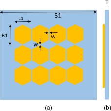
By utilizing the concepts of CMA, we have proposed an MTS structure as shown in Fig. 1, and modal behavior of MTS structure without ground is analyzed with the help of CST Microwave Studio. The structure configuration includes the 3 × 4 hexagonal-shaped MTS layer printed on the top layer of Rogers RT5880 (with  ${\varepsilon _r}$ = 2.2 and thickness (T) of 3.2 mm) substrate.
MTS without ground: (a) upper surface and (b) side surface. Dimensions are L1 = 9, B1 = 12.2, W = 0.4, S1 = 55, T = 3.2 (unit: mm).
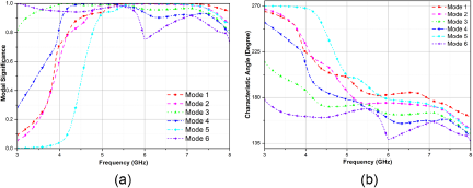
As depicted in Fig. 2, the initial six current modes are computed, and parameters pertinent to CMA, namely MS and CA, are determined using equations (3) and (4). From Fig. 2(a), we have observed that current mode 1 (J1), mode 2 (J2), mode 3 (J3), and mode 5 (J5) are the resonating modes as their MS levels are greater than or equal to 0.7 at 6.5 GHz. As shown in CA in Fig. 2(b) and from equation (4), it is clear that the phase difference between the modes J1 and J2 is not 90°. Thus, as per the condition to achieve CP, the difference in phase between CA of two modes is to be close to 90°. Further, for excitation of modes in MTS, we need to provide feed, therefore, a ground is attached to the structure with a parallel slot.
CMA analysis of MTS (a), MS, and (b) CA.

CM analysis of MTS with slotted ground plane
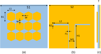
In this section, a parallel slotted ground structure is introduced beneath main substrate to achieve a low-profile antenna design, incorporating concept of CPW feed. The MTS layer with this slotted ground is shown in Fig. 3. The first six current modes are computed and both parameters, MS and CA, are analyzed, as shown in Fig. 4. Notably, new current modes are produced by insertion of the slotted ground. In Fig. 4(a), current modes J1, J2, J3, and J4 are recognized as resonant modes, with MS values approaching or above 0.7 after 4 GHz.
MTS with slotted ground: (a) top surface, (b) bottom surface, and (c) side surface. The dimensions are L1 = 9, B1 = 12.2, W = 0.4, S1 = 55, T = 3.2, S2 = 55, L2 = 15.4, F1 = 0.4, H1 = 27, B2 = 1, M1 = 5.3 (unit: mm).
CMA analysis of MTS with ground (a) MS and (b) CA.
Also, to understand CP behavior, current distribution pattern is calculated at 5.2 GHz. After analyzing current distribution pattern of modes as shown in Fig. 5, we have concluded that mode 1 (J1) and mode 2 (J2) are required modes for generating CP because both modes have orthogonal surface current distribution. It is seen that current distribution pattern of mode 1 (J1) is on the x-axis and that of mode 2 (J2) is on the y-axis. This makes J1 and J2 good candidates for realizing CP. In addition, gain performance of antenna is verified by plotting 3D far-field pattern at 5.2 GHz shown in Fig. 6. From Fig. 6, it is evident that mode 1 and mode 2 are the essential modes for achieving gain enhancement because of their directive radiation patterns. Furthermore, as indicated in Fig. 5, modes 1 and 2 exhibit in-phase currents, which result in a broadside radiation pattern. On the other hand, modes J3, J4, J5, and J6 have opposing phases, rendering them unsuitable for the desired outcome, leading to a radiation null at the boresight.
Distribution of surface current: (a) mode 1, (b) mode 2, (c) mode 3, (d) mode 4, (e) mode 5, and (f) mode 6 at 5.2 GHz.

3D radiation pattern: (a) mode 1, (b) mode 2, (c) mode 3, (d) mode 4, (e) mode 5, and (f) mode 6.

Upon analyzing the structure using CMA, it is concluded that two modes, J1 and J2, are ideal for generating circular polarization and achieving gain enhancement. However, it is worth noting that phase difference (CA) is not exactly 90° for modes 1 and 2 as shown in Fig. 4(b). Therefore, it is necessary to introduce a modified slot to achieve this 90° phase difference effectively for circular polarization generation.
CM analysis of MTS antenna with modified slotted ground
Observing current distribution in both modes 1 and 2 in Fig. 5, it’s evident that mode 1 concentrates its current at top and bottom of the MTS, while mode 2 does so at the left and right sides. To achieve circular polarization at 5.2 GHz, ground slot is appropriately modified by extending it in the x and y directions, as shown in Fig. 7. This adjustment maintains the original MTS dimensions.
MTS with modified ground: (a) top, (b) bottom, and (c) side views. The dimensions are L1 = 9, B1 = 12.2, W = 0.4, S1 = 55, T = 3.2, S2 = 55, L3 = 8.55, L4 = 15.5, L5 = 9.2, L6 = 3, F1 = 0.4, H1 = 27, B2 = 1, M1 = 5.3 (unit: mm).

Circular polarization is attained by ensuring a 90° phase difference. However, introduction of additional modes complicates this condition. When magnitudes of currents in orthogonal directions differ, it results in elliptical polarization rather than a pure circular state. This deviation is measured by the axial ratio, a crucial parameter for evaluating circular polarization quality. Examining the impact of other modes on the axial ratio requires understanding their contributions to current magnitudes. Each mode introduces its unique currents, and their interaction can disrupt the desired 90° phase relationship, leading to variations in the axial ratio and deviating from ideal circular polarization.
To tackle this challenge, a thorough examination of contributions from each mode is essential. Identifying and suppressing unwanted modes using CMA becomes necessary. This can be achieved through geometrical alterations in the structure or adjustments to the feed. In the proposed design, Fig. 5 illustrates the surface current distribution of each mode. Analyzing this, we observe that mode 1 and mode 2 have a higher density of surface current around the center of the MTS. To excite mode 1 and mode 2, we need to excite patches around the center of the MTS which is done by using the proposed feed. Thus, designing an optimized feed allows us to suppress unwanted modes and achieve the desired circular polarization.
Applying CMA to this modified structure reveals that modes 1 and 2 resonate effectively, and there’s an approximately 90° phase difference between them around 5.2 GHz, as indicated in Fig. 8(a) and (b). Thus, this modified design is confirmed to produce circular polarization at 5.2 GHz.
CMA analysis: (a) MS and (b) CA of modified ground MTS.

Proposed MTS-based antenna design
As established in the previous section, it’s evident that the modified structure is capable of generating circular polarization at around 5.2 GHz. To validate this, a CPW feed is applied to the modified structure, essentially converting the previously designed ground slot into a CPW feed. This conversion is based on the consideration of the current distribution pattern for modes 1 and 2. As a result, the CPW feed, which transforms the slot into CPW feed, effectively and simultaneously excites current modes 1 and 2. The designed antenna with these changes is depicted in Fig. 9, maintaining the same dimensions as in Fig. 7.
Geometry of the hexagonal-shaped MTS antenna: (a) top view, (b) back view, and (c) side view.

Further, the points for the selection of antenna geometry, design methodology, and novelty of the structure are as follows:
(1) Single-layer MTS: Instead of conventional multilayered structures, this antenna utilizes a single MTS layer printed on the top of the substrate. This single layer reduces fabrication complexity and improves compactness.
(2) 4 × 4 array of hexagonal patches: The MTS layer comprises an array of hexagonal-shaped patches. These patches act as resonant elements, manipulating the electromagnetic field to achieve desired radiation characteristics. Hexagons possess inherent symmetry, offering uniformity in the arrangement of patches, which simplifies analysis and design using techniques like CMA. The shape and dimensions of the hexagon can be readily adjusted to manipulate its resonant frequency and radiation characteristics.
(3) CPW-fed slotted ground: The bottom layer features a modified CPW feed line connected to a slotted ground plane utilized to excite the desired CMs. This configuration efficiently excites the MTS layer and contributes to circular polarization.
The simulation results indicate that IBW of the hexagon-shaped MTS antenna spans 84.3%, ranging from 3.7 to 9.1 GHz as shown in Fig. 10. Furthermore, the structure achieves circular polarization, with a dual 3-dB ARBW of 18.6%, ranging from 4.96 to 5.98 GHz, and 3.74%, ranging from 8.38 to 8.7 GHz as shown in Fig. 11. In addition, Fig. 12 illustrates the realized gain of the proposed MTS antenna, reaching a peak value of 10.08 dBic at 7.1 GHz.
Simulated reflection coefficient of the proposed CP antenna.

Axial ratio of the proposed CP antenna.

Gain of the proposed CP antenna.

Experimental setup for measuring proposed antenna
Figure 13 depicts the configuration for measuring far-field parameters to test the proposed antenna. In the anechoic chamber, the radiation patterns, axial ratio, and gain values are measured [Reference Balanis37]. At one end of the anechoic chamber is a testing antenna, and at the other end is a normal gain horn antenna.
Anechoic chamber measurement setup.

The far-field method, a common approach to antenna radiation pattern measurement, involves placing the proposed antenna at a sufficient distance from a measuring antenna. This distance ensures that radiated waves are approximately planar and uniform. The measuring antenna rotates around the test antenna, recording received signal strength at various angles. The collected data are then used to create a polar plot, providing a visual representation of the antenna’s radiation pattern in a specific plane. The orthogonality in the polarization can be accomplished by measuring axial ratio by rotating the standard gain antenna by 90° [Reference Toh, Cahill and Fusco38]. Gain is measured using the replacement method in a similar setup.
Result and discussion
The photograph of fabricated antenna is depicted in Fig. 14. The simulated and measured results of the antenna are identical with some discrepancies that occur due to fabrication tolerance. The measured results indicate that the IBW of the antenna is 84.3%, ranging from 3.7 to 9.1 GHz as shown in Fig. 15. The antenna also has a dual 3-dB ARBW that ranges from 4.96 to 5.98 GHz (18.6%) and from 8.38 to 8.7 GHz (3.74%) as depicted in Fig. 16. Figure 17 shows the measured gain values of antenna and it is observed that proposed design shows stable gain within the IBW of antenna with peak value of 10 dBic at 7.1 GHz. The radiation pattern of the CP single-layer hexagonal-shaped MTS antenna at 5.2 GHz and 8.5 GHz is presented for both the E-plane and H-plane. Figure 18(a) displays the radiation pattern in the xz- and yz-plane at 5.2 GHz and it is observed that the antenna exhibits left-hand circular polarization (LHCP) in the boresight direction while Fig. 18(b) in the xz- and yz-plane at 8.5 GHz. The radiation pattern exhibits LHCP in the boresight direction with a cross-polarization level exceeding 15 dB in the broadside direction.
Photograph of fabricated antenna.

Simulated and measured reflection coefficients of the proposed antenna.

Simulated and measured axial ratio of the antenna.

Simulated and measured realized gain of the antenna.

Measured normalized radiation patterns at (a) 5.2 GHz and (b) 8.5 GHz.

It is noteworthy that the results presented in the statement validate the design and functionality of the fabricated antenna. The measurement results show that the antenna is capable of operating over a wide frequency range and has a high gain, which makes it suitable for use in various sensing applications. The simulation results also provide insight into the expected behavior of the antenna, which can aid in the optimization of the design parameters.
Comparative analysis in detail
This information provides valuable insight into the performance of the proposed antenna in terms of its radiation characteristics and how it fares in comparison with other existing designs as shown in Table 1. It is observed that proposed design has wide 3-dB ARBW as compared to papers [Reference Deng, Lv and Feng11–Reference Poordaraee, Oraizi, Khajevandi and Glazunov13, Reference Hussain, Tran and Lê22, Reference Rajanna, Rudramuni and Kandasamy24, Reference Suyan, Lal Lohar, Dhote and Solunke30–Reference Yousfi, Lamkaddem, Abdalmalak and Vargas32]. The proposed design has peak gain of 10.08 dBi which is more as compared to other designs with compact size as compared to papers [Reference Hussain, Tran and Lê22, Reference Yousfi, Lamkaddem, Abdalmalak and Vargas32]. The improvement in the axial ratio and return loss bandwidth further indicates that the proposed antenna is a promising candidate for various sensing and communication applications.
Comparison of the designed structure with CP antennas discussed in the literature

Conclusion
In this work, we have introduced a design for a low-profile MTS antenna with high gain and CP. The utilization of CMA theory has enabled us to determine the optimal feed position and structure, leading to the excitation of required modes and resulting in a compact antenna design characterized by high gain and wideband CP. Our proposed CP MTS antenna exhibits notable performance, boasting an impressive IBW of 84.3% and dual 3-dB ARBWs measuring 18.6% and 3.74%, respectively. Furthermore, the antenna’s overall size of 0.67λ0 × 0.67λ0 × 0.040λ0 confirms its compact footprint. The radiation pattern of the proposed antenna is bidirectional, achieving a peak gain of 10.08 dBi at 7.1 GHz. The future work includes further optimization of CMs of proposed design to converge high gain and 3-dB ARBW regions. Additionally, implementing the antenna on flexible substrate to explore its viability for wearable applications.
Author contributions
D.G. and A.S. derived the theoretical analysis of CMA. A.S. performed the simulations. All authors contributed equally to analyzing results and reaching conclusions, and in writing the paper.
Funding statement
This research received no specific grant from any funding agency, commercial or not-for-profit sectors.
Competing interests
The authors report no conflict of interest.

Deepak Gangwar received his B.Tech. degree from Uttar Pradesh Technical University, Lucknow, India, in 2008, and M.Tech. degree from Guru Gobind Singh Indraprastha University, Delhi, India, in 2011. He received his Ph.D. degree in Electronics Engineering from Indian Institute of Technology (ISM), Dhanbad, India. Currently, he is working as Associate Professor in Department of Electronics and Instrumentation, Mahatma Jyotiba Phule Rohilkhand University (MJPRU), Bareilly, Uttar Pradesh, India. His research interests include metamaterial-based antennas, ultra-wideband antennas, metamaterial filters, frequency selective surface, metasurface, and RCS reduction.

Ankit Sharma received his B.Tech. degree in Electronics and Instrumentation Engineering, in 2008, and M.Tech. degree in Signal Processing, in 2012, from Ambedkar Institute of Advanced Communication Technologies and Research, Delhi, India. He received his Ph.D. degree in Electronics Engineering from Indian Institute of Technology (ISM), Dhanbad, India, in 2021. His current research interests focus on high-gain antenna design using CMA, metasurfaces, and antenna design for mobile base station applications.



