I. INTRODUCTION
Recently, there has been renewed interest in the implementation of traditional microwave passive circuits in monolithic silicon technologies. The need for having composite analog and microwave design techniques in SiGe circuit design in the radio-frequency domain is one of the reasons for this resurgent interest [Reference Reynolds, Floyd, Pfeiffer and Zwick1]. There are more challenges in the design and implementation of diverse circuits using silicon technologies ranging from passive circuits like couplers and filters to active circuits like I/Q up/down converters and balanced amplifiers employing distributed passive circuitry in the microwave and millimeter-wave bands.
Quarter-wavelength transmission lines (T-lines) are employed in many microwave and millimeter-wave circuits such as couplers, mixers, bias networks, and matching circuits. However, if this configuration is designed conventionally, it is large and expensive when incorporated into SiGe/Complementary metal–oxide–semiconductor (CMOS) monolithic microwave integrated circuits (MMICs) and can be a major drawback when designing an MMIC-based system. Therefore, miniaturizing such a structure without affecting performance is highly desirable. Techniques that reduce these dimensions are of great interest as they lead to higher density and more cost-effective implementations.
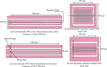
In this paper, we investigate the miniaturization of λg/4 coplanar waveguide (CPW) series/shunt stubs taking advantage of the ability to co-locate interdigital lines inside the center conductor of the stubs (Fig. 1) to make novel miniature CPW stubs. It is shown that the structure enables strong coupling and enhances the loaded capacitance. This approach offers new possibilities for the realization of monolithic millimeter-wave integrated circuits with good integration density.
Conventional and novel loaded CPW SW series and shunt stubs.

Finally, bandpass filters using the proposed stubs are designed to illustrate how effectively such techniques can be used to achieve a slow-wave (SW) effect without occupying extra surface area. A commercial foundry process using commercial 0.35 µm SiGe Heterojunction bipolar transistor (HBTs) is used for fabrication.
II. SILICON-COMPATIBLE CPW CANDIDATE
T-lines are important structures for millimeter-wave design. At these frequencies, the reactive elements needed for matching networks and resonators become increasingly small, requiring inductance values on the order of 50–250 pH. Given the quasi-transverse electromagnetic (quasi-TEM) mode of propagation, T-lines are inherently scalable in length and are capable of realizing precise values of small reactance. Additionally, interconnect wiring can be modeled directly when implemented using T-lines. Another benefit of using T-lines is that the well-defined ground-return path significantly reduces magnetic and electric field coupling to adjacent structures.
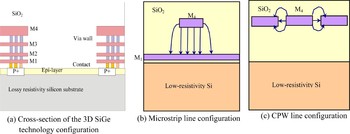
Microstrips and CPWs are commonly used planar T-lines in silicon (Fig. 2). Both have relatively low loss, either because the metal ground plane shields the substrate in the case of microstrips, or because the electromagnetic field is largely moved away from the silicon substrate in CPWs. The characteristic impedance of a CPW line can be designed by adjusting the spacing between signal and ground line, whereas that of a microstrip can be coarsely changed by the chosen metal layer for the ground plane. Furthermore, layout design rules in silicon technologies make it difficult to achieve a wide range of characteristic impedance while maintaining low loss.
Microstrip and CPW lines in silicon, showing field distribution (not to scale). The signal line is usually built on the top metal layer.

In the microstrip case (Fig. 2(b)), the distance between signal line and ground plane is limited, and so is the signal line width. Therefore, on-chip microstrips usually can only achieve relatively low impedance. CPWs make it easier to connect transistors in layout, and tend to be more compact than microstrips. Hence, they are sometimes preferred to microstrips at microwave frequencies.
III. CPW SW STUB STRUCTURES
SW planar T-lines have been realized in various forms since the mid-1970s. In general, a SW line exhibits a phase velocity that is reduced relative to a comparable uniform line, such that the phase shift per unit length (i.e. the phase constant) is increased. The SW effect has been achieved using meandered lines, metal–insulator–semiconductor lines, and periodically loaded lines [Reference Weiss2–Reference Spickerman and Dagli4].
Figure 1 illustrates the SW stubs studied in this work. As shown in Fig. 1, periodic slots are cut into the center conductor of CPW series and shunt stubs. The periodic slots result in a slower phase velocity compared to the standard geometry [Reference Harvey5]. There are any number of geometries which can achieve phase velocity slowing. The one chosen in this work was selected because of its simplicity and ease of fabrication.
A) Theory
The phase velocity of SW modes propagating along a transmission line is determined by the energy stored in sections of the circuit. Lumped-element circuit theory states that the phase velocity (Vp) is dependent on both inductance per unit length (L) and capacitance per unit length (C) when the wave propagates along the low-loss conducting transmission line. The relationship is expressed by

As indicated in (1), changing both L and C can change the phase velocity. However, in a conventional distributed TEM transmission line, L and C are also related to each other. This would make it impossible to modify the phase velocity by changing either L or C without affecting the other. This dilemma can be overcome by replacing physically uniform lines with periodically loaded lines.
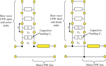
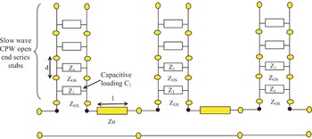
A simple way to make a SW structure is to introduce a series of slots in the center conductor of a conventional quarter-wavelength stub. The SW stubs, as shown in Figs 1(b) and 1(d), are composed of symmetrical coplanar interdigital structures located on both sides of the center conductor of the stubs. The two circuits can be regarded as capacitively loaded SW structures, as shown in Fig. 3.
Equivalent circuits of CPW SW stubs.

B) Design of SW open-end series and short-end shunt stubs
A standard open-end series stub in CPW [Reference Hettak, Dib, Omar, Delisle and Stubbs6–Reference Weller and Katehi7] is designed by deforming the center conductor with two slots on either side connected to each other, as illustrated in Fig. 1(a). This creates an open circuit at the ends of the slots, which translates to a short circuit at the input port at the resonant frequency, and gives a bandpass response because these inner slots are quarter wavelength long. In order to obtain the slowing of the velocity (hence, a reduction in size), the inner slots are simply meandered at periodic intervals to take the form of a seven finger CPW interdigitated capacitor. Therefore, the conventional open-end CPW series stub is loaded with capacitive fingers, as shown in Fig. 1(b). It should be mentioned that interdigitated capacitive fingers within the open-end CPW series stub are oriented in the direction parallel to the direction of propagation.
The conventional short-end shunt stub [Reference Hettak, Dib, Omar, Delisle and Stubbs6] is identical to the open-end series stub except that the center conductor slot on either side is not connected to the ground plane slots, and a bridge is used to connect the center conductor to the ground plane of the main CPW line, as illustrated in Fig. 1(c). At the resonant frequency, these inner slots in parallel translate a short circuit to an open circuit effect at the input port, resulting in a bandpass response.
The capacitive loading has been produced by meandering the inner slots at a periodic inter-stub spacing, d, as shown in Fig. 3. Therefore, the CPW short-end shunt stub is loaded with capacitive fingers as shown in Fig. 1(d). It can be expected that the resonance frequency of the capacitively loaded CPW stubs will be shifted down as the number of interdigitated fingers increases.
The reduction in size of these types of stubs, and their performance, can be controlled by the fingers within the CPW stubs. Moreover, the fundamental resonance frequency of the CPW stubs might be estimated by assuming that the total length of the meandered slots equals the guided quarter-wavelength (λg/4).
IV. THEORETICAL VALIDATION
The SW and conventional CPW series and shunt stubs were designed for a 0.35 µm SiGe HBT process using a full-wave EM simulator (ADS Momentum™). To determine the resonance characteristics of the capacitively loaded CPW series and shunt stubs, we have simulated a CPW open-end series stub with N = 6, where N is the number of capacitive fingers, as well as a CPW short-end shunt stub with N = 2.
To characterize the size reduction and performance of the novel stub, four CPW stubs (including conventional CPW open-end series and short-end shunt stubs, a CPW short-end shunt stub loaded with two capacitive fingers, and a CPW open-end series stub loaded with six capacitive fingers) were designed with different lengths for approximately the same resonance frequency around 60 GHz, and simulated using the full-wave simulator. In this case, the dimensions of the stubs were 660 × 100 µm for conventional CPW stubs, 150 × 270 µm for the CPW open-end series stub loaded with six fingers, and 360 × 200 µm for the CPW short-end shunt stub loaded with two fingers. These dimensions mean that the six finger CPW series stub has a size reduction of about 40%, as compared with the conventional CPW series stub.
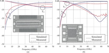
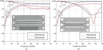
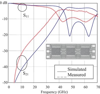
S-parameters of the fabricated circuits were measured up to 70 GHz using a vector network analyzer. Simulated and measured frequency responses of the open-end series and short-end shunt stubs, designed at approximately the same resonance frequency, are shown in Figs 4 and 5, respectively.
Measured and simulated characteristics of (a) conventional and (b) novel loaded CPW SW open-end series stubs (photos not at same scale).

Measured and simulated characteristics of (a) conventional and (b) novel loaded CPW SW short-end shunt stubs (photos not at same scale).

Figure 4 shows that there is 10 dB improvement in return loss at 60 GHz for the capacitively loaded CPW series stub with six fingers as compared to the conventional series stub. The insertion loss remains approximately the same.
Similarly, Fig. 5 shows a significant improvement of 10 dB for S 11, and a 3 dB improvement for S 21, at 60 GHz for the capacitively loaded CPW shunt stub with two fingers as compared to the conventional shunt stub. As can be seen, there is a reasonable agreement between the simulated and measured frequency responses. The discrepancy between the measured and simulated results can be attributed to the estimated value of the conductivity of the lossy silicon that the silicon foundry provides.
V. 60 GHZ BANDPASS FILTERS BASED ON SW CPW SERIES/SHUNT STUBS
Microwave passive bandpass filters are of great interest in the development of 60 GHz unlicensed millimeter-wave communication systems [Reference Doan, Emami, Niknejad and Brodersen8]. Due to the low fabrication cost and mature process, standard SiGe technology has always been preferable in industry. Unfortunately, the low-resistivity silicon substrate in a standard SiGe process always suffers from high-dielectric loss and introduces significant crosstalk between devices integrated on the silicon wafers. Many approaches have been proposed to overcome this limitation, including ion implantation [Reference Chin, Lee, Lin and Horong9], micromachining technique [Reference Nam and Kwon10], and thick isolated interface layer [Reference Blondy, Brown, Cros and Rebeiz11]. However, these nonstandard processes require additional processing steps or packaging considerations, thus tremendously increase the process complexity and cost. In this section, we present a novel class of millimeter-wave bandpass filters with reduced loss and miniaturized size using the capacitively loaded CPW series and shunt stubs introduced in Section III.
A variety of techniques exist for the implementation of bandpass filters. For CPW applications, filters using a combination of series and/or shunt tuning stubs have received considerable attention. By cascading multiple open-end stubs in series, it is quite simple to realize a bandpass response with high out-of-band rejection and low-loss performance [Reference Hettak, Dib, Omar, Delisle and Stubbs6]. The passband resonance of an open-end series stub occurs when the mean length is λg/4, and the associated radiation loss is very low due to the location of the stub within the center conductor. The stopband resonance occurs when the stub length is λg/2 and is considerably stronger than the passband resonance. A typical topology of a CPW bandpass filter is shown in Fig. 6, which consists of a cascade of alternate quarter-wavelength CPW shunt stubs and quarter-wavelength CPW connecting lines.
Standard CPW bandpass filter that consists of three open-end series stubs.

However, if this configuration is designed conventionally, it will occupy a large portion of the SiGe wafer and this is expensive when incorporated into MMICs, which can be a major drawback when designing an MMIC SiGe-based system. Therefore, miniaturizing such a structure without affecting the performance is highly desirable.
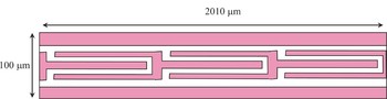
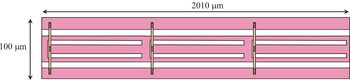
One technique of particular interest is to use the capacitively loaded CPW series stubs introduced in Section III. Thus, this standard CPW bandpass filter that consists of three open-end series stubs is modified by replacing its series stubs with capacitively loaded stubs as shown in Fig. 7. The simplified schematic representing the miniaturized filter is shown in Fig. 8.
Compact CPW bandpass filter based on SW CPW series stubs.

Equivalent circuit of compact CPW bandpass filter based on SW CPW open-end series stubs.

Using this approach, the size is significantly reduced compared to the standard topology. This attractive technique expands the design freedom and provides an opportunity for designing original structures with high integration densities. It is worth noting that the proposed capacitively loaded stubs are entirely responsible for the major reduction in size, shown in Fig. 7, and is not possible using other realizations such as microstrip technology.
A three-section SW open-end series stub bandpass filter was fabricated using a commercial 0.35 µm SiGe HBT process. The total dimensions of the filter are 520 µm long and 270 µm wide. These dimensions mean that the proposed SW bandpass filter has a size reduction of about 25%, as compared with the conventional CPW bandpass filter that consists of three open-end series stubs.
The simulated and measured responses are shown in Fig. 9. We can see that there is reasonable agreement between simulated and measured results. As explained earlier, the discrepancy between the measured and simulated results can be attributed to the estimated value of the conductivity of the lossy silicon that the silicon foundry provides. The measured reflection coefficient is lower than −9 dB with a relatively flat insertion response having maximum attenuation of 6 dB from 38 to 65 GHz. The measured response is centered around 55 GHz with a 62% bandwidth.
Measured and simulated S-parameters of compact bandpass filter based on SW open-end series stubs (photos not to scale).

By expanding the above idea and by exploiting the flexibility of the CPW technology, an alternative CPW bandpass filter topology is presented in Fig. 10. It shows the possibility of building a cascade of quarter-wavelength CPW short-end shunt stubs by locating the shunt stubs in the center conductor of the main CPW line.
CPW bandpass filter that consists of three short-end shunt stubs printed on the center conductor of the CPW line.

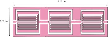
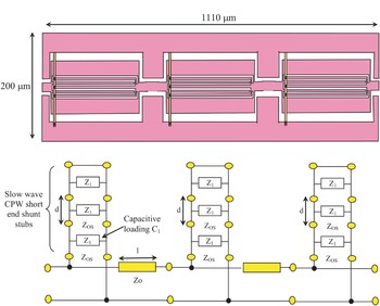
The proposed filter (Fig. 10) has a large dimensions because it is made of three quarter-wavelength (λg/4) stubs. To overcome this problem, an alternative topology that consists of a cascade of SW CPW short-end shunt stubs introduced in Section III. The topology of this SW bandpass filter and its simplified schematic are illustrated in Fig. 11.
Miniature CPW bandpass filter based on SW CPW short-end shunt stubs and its equivalent circuit.

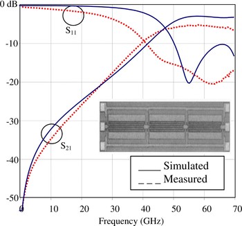
A three-section SW bandpass filter based on capacitively loaded CPW short-end shunt stubs was fabricated using a commercial 0.35 µm SiGe HBT process. The total dimensions of the filter are 1110 µm in length and 200 µm in width. These dimensions mean that the proposed SW bandpass filter has a length reduction of about 66%, as compared with the standard CPW bandpass filter that consists of three short-end shunt stubs.
There is reasonable agreement between simulated and measured results, as shown in Fig. 12. As previously noted, we believe that the discrepancy between the measured and simulated results can be attributed to the estimated value of the conductivity of the lossy silicon that the silicon foundry provides.
Measured and simulated S-parameters of miniature SW bandpass filter based on capacitively loaded CPW short-end shunt stubs.

The measured response (Fig. 12) shows an insertion loss about 5.2 dB from 45 to 65 GHz, with a reflection coefficient that is lower than −15 dB. The filter measured response is centered around 55 GHz with a bandwidth more than 60%.
VI. CONCLUSIONS
A new construction technique of compact CPW series and shunt stubs using SW structures are proposed, designed, and fabricated using a commercial 0.35 µm SiGe process. It has been shown that the periodically loaded CPW stubs have not only a smaller size, which utilizes the circuit area in a highly efficient manner, but also a higher performance as compared with the conventional quarter-wavelength CPW stubs. Furthermore, the performance of the proposed structures is comparable to that of the conventional quarter-wavelength CPW series and shunt stubs. The validity of the design concept is confirmed by both simulation and experiment. Finally, two novel variants of miniature SW millimeter-wave bandpass filters based on the proposed capacitively loaded CPW series/shunt stubs are designed and measured, demonstrating that the proposed SW CPW stubs can provide a reduction of size and improved performance.
 Khelifa Hettak received the Dipl.-Ing. in telecommunications from the University of Algiers, Algeria, in 1990, and his M.A.Sc. and Ph.D., in Signal Processing and Telecommunications, from University of Rennes 1, France in 1992 and 1996, respectively. In January 1997, he has been with the Personal Communications Staff of INRS-Télécommunications. He joined the electrical engineering department of Laval University since October 1998 as an associate researcher, where he was involved in RF aspects of Smart antennas. Since then, August 1999, he has been with Terrestrial Wireless Systems Branch at Communications Research Centre (CRC), Ottawa, Canada, as Research Scientist. He was involved in developing MMICs at 60 GHz, low temperature cofired ceramic (LTCC) packaging, and RF MEMS switches.
 Gilbert A. Morin received his B.Sc.A. degree in Engineering Physics from Ecole Polytechnique de Montréal, in 1977, and his M.A.Sc. and Ph.D., in Electrical Engineering, from the University of Toronto in 1980 and 1987, respectively. Since then, he has been working at the Defence R&D Canada – Ottawa as a Defence Scientist in the Advanced Military Communications Systems group. His research interests are: GaAs MMIC, micro-electromechanical systems (MEMS), low-temperature co-fired ceramic (LTCC) packaging, reflector and lens antennas, phased arrays, and software-defined radio front-ends.
 Malcolm G. Stubbs received his B.., M.E., and Ph.D. degrees from the University of Sheffield, Sheffield, U.K., in 1970, 1972, and 1976, respectively. From 1975 to 1978, he was with the Communications Research Centre (CRC), Ottawa, Ontario, Canada, under a National Research Council Post-Doctoral Fellowship Program. He then joined the Allen Clarke Research Centre, Caswell, U.K., where he was engaged in GaAs MMIC research. In 1981, he returned to the CRC, where he is currently responsible for the development of planar microwave and millimeter-wave circuits. His interests include the modeling and application of MMICs, MEMS, and LTCC technologies to high-frequency components for communications systems.