


1 Introduction
In the era of Industry 4.0, Radio-Frequency Identification (RFID) systems are emerging as one of its essential components (Trappey et al., Reference Trappey, Trappey, Govindarajan, Chuang and Sun2017). RFID-based systems use radio-frequency electromagnetic fields for data exchange without line-of-sight interactions making them valuable for tasks within the realm of the Internet of Things, that is for entity tracking (e.g., Gnimpieba et al., Reference Gnimpieba, Nait-Sidi-Moh, Durand and Fortin2015; Velandia et al., Reference Velandia, Kaur, Whittow, Conway and West2016), asset management (e.g., Campbell et al., Reference Campbell, Jardine and McGlynn2016; Qian et al., Reference Qian, Zhang, Cao and Zhang2018), identification (e.g., Vogt, Reference Vogt2002; Fahim et al., Reference Fahim, Elbatt, Mohamed and Al-Ali2018), access control (e.g., Robert et al., Reference Robert, Maciej, Tadeusz, Zbigniew and Kazimierz2016; Qi et al., Reference Qi, Zheng, Li, Liu and Qiu2016) and automation (e.g., Colella et al., Reference Colella, Catarinucci and Tarricone2016; Gandino et al., Reference Gandino, Montrucchio, Rebaudengo and Sanchez2009).
The first commercial use of RFID technology goes back to the late 60s in the domain of electronic article surveillance equipment (Landt, Reference Landt2005). However, it is in the last decade that RFID technology has gained acceptance in wireless communications technologies due to its accuracy, reliability and continuously decreasing costs (Beck, Reference Beck2018). IDTechEx estimates that the total RFID market will be worth $13.4 billion in 2022 (Raghu, Reference Raghu2018), while even more optimistically, the Market Research Future expects that by 2023 the market will grow to $31.8 billion, at approximatelly 15.6% of the compound annual growth rate between 2017 and 2023Footnote 1.
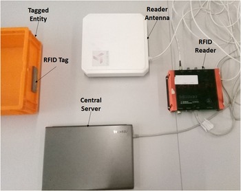
As it is shown in Figure 1, a typical RFID system is usually comprised of an RFID reader, a reader antenna, an RFID tag attached to an entity of interest and a middleware (i.e., a central server) that allows users to manage and analyze the collected data (Klair et al., Reference Klair, Chin and Raad2010). One of the most challenging tasks that end users have to face is to select amongst the plethora of RFID systems, readers, tags and antennas the ones that fit best to their needs based on the properties of their domain of interest (e.g., operating frequency, functionality, form, size, attachment method, resistance to chemicals, extreme temperatures). At the same time, they have to consider the wide range of factors (e.g., the enviroment, the material and size of the entity to be tagged, the attachment method, the technical and physical characteristics of the tag and the reader) and the interrelations amongst the parameters that affect the performance of the RFID system (Mitchell, Reference Mitchell2013).
A typical RFID system consists of an RFID reader, which is connected to a reader antenna, an RFID tag and a central server.

In cases where the available market of RFID systems does not meet the user’s requirements, custom-made RFID tags have to be developed, according to the respective regulations and standards (e.g., GS1 Global Office, 2019). For these cases, the RFID expert not only has to take into account the aforementioned factors, but at the same time has to retrieve more detailed electromagnetic performance information (Tribe, Reference Tribe2019). For instance, besides the type of the material of the item, the expert has to be also aware of its relative permittivity and loss tangent as both factors are crucial for the design of the tag antenna. In addition, the impedance of the RFID chip needs to match that of the antenna to ensure optimum power transfer between the reader and the tag (Galehdar et al., Reference Galehdar, Thiel and O’Keefe2007). Hence, an integrating schema that will encapsulate all this information in a form that is both human and machine processible is required to enhance the efficiency the RFID system design.
On top of this, the components of an RFID system can be off-the-shelf items designed by a number of manufacturers, or custom designs for a specific application. However, suppliers’ information about these components is often derived from manufacturer data sheets, which use their own terminology, making the problem of identifying the right RFID system, reader or tag even harder (e.g., Alien Technology Corporation 2017b; NXP, 2019). There are also cases where the information about the elements of these componets (e.g., the chip of a tag) and their functionality is limited, hence the interested user has to seek for further information (e.g., whether the communication protocol supports encrypted information) in external resources (the actual protocols). Finally, once the best suited RFID system is specified, another issue that arises is the location of the tag (and possibly of the reader and antenna) in order to exploit reliably and robustly the full potential of the system.
Currently, all this information is available in human-readable texts (i.e., suppliers’ and manufacturers’ datasheets, regulations, standards, research papers and white papers, e.g., Alien Technology Corporation 2017b; Rain RFID Alliance 2018; GS1 Global Office 2019) that cannot be processed by machines leaving the laborious task of identifying and configuring the right RFID system to the end user. To date, no decision support tools exist for the identification of the right RFID technology based on the needs of the user. Hence, the aim of the research outlined in this paper is to provide a core framework that will enable the representation of all the information related to RFID system configuration under one formal, semantically enriched, integrating schema that is machine processible. For this purpose, semantic technologies have been adopted and, in particular, the novel RFID System Configuration Ontology (RFID SCO) is developed.
An ontology is a formal conceptual schema that describes a domain of interest (Mehdi et al., Reference Mehdi, Kharlamov, Savković, Xiao, Kalayci, Brandt, Horrocks, Roshchin and Runkler2017). It is composed of entities and relationships between them. Its formal semantics are defined by using a knowledge representation language (e.g., Description Logics Baader et al. 2003) to ensure a precise specification of the meaning of the described elements that is both machine and human readable. The machine readability allows automated logical deduction techniques (i.e., reasoning) on the conceptual schema deriving implicit information from the explicit representation (Baader et al. Reference Baader, Calvanese, McGuinness, Nardi and Patel-Schneider2003). In the RFID system context, the reasoning tools can aid the end user to identify and configure the most appropriate RFID system based on domain criteria.
The purpose of this research work is to develop the domain-specific ontology RFID SCO, which will enable: (i) non-RFID experts to choose the most suitable RFID system (i.e., reader or tag) according to their needs, (ii) RFID experts to retrieve all the relevant information required for the efficient design of the corresponding RFID system (i.e., reader or tag), (iii) a shared understanding of the RFID technology domain. This will enhance not only the decision support processes, but also the effective information sharing in machine-to-machine scenarios. The recent advances in cloud robotics (e.g., de Freitas et al., Reference de Freitas, Olszewska, Carbonera, Fiorini, Khamis, Ragavan, Barreto, Prestes, Habib, Redfield, Abdelghani, Paulo, Julita, Ricardo, Elisa, Alberto, Andrea, Jõao and Howard2020) and in system of systems (e.g., Choi & Shen, Reference Choi and Shen2016) highlight that the RFID SCO could be leveraged to communicate behavioural triggers and capabilities amongst robots. For instance, in cases where robots are equipped with RFID systems (e.g., Morenza-Cinos et al., Reference Morenza-Cinos, Casamayor-Pujol, Soler-Busquets, Sanz, Guzmán and Pous2017) for automatic inventorying and locating, if the RFID SCO and a set of ontologies representing the capabilities of the robots, along with the relevant databases, is stored in the cloud, then data sharing and management amongst the multi-robot systems will be efficiently facilitated.
The contributions of this work can be outlined as follows: (i) A corpus of 35 competency questions related to RFID system decision-making is provided. These questions are resulted from interviews with domain experts and their usability is verified by two real-world use case scenarios. They form a very first corpus of questions, which we plan to enrich and leverage in the future for the performance of natural language question answering techniques. (ii) The required knowledge to address the competency questions is specified, and formalized, by using the well-known decidable ontology language OWL DL, forming the RFID SCO ontology. Finally, this research work brings a comprehensive methodology for ontology development and use in the RFID domain by providing illustrating examples applied to the aforementioned real-world use case scenarios.
This paper is structured as follows. First, after an overview of the related work (2), a short introduction to RFID system technology is presented in Section 3. In Section 4, the description of ontology development process is presented: initially, a brief description of the followed methodology, the specification of requirements is defined (Section 4.1), where two real-world use cases and a set of competency questions are presented; then, relevant ontologies that can be reused are identified (Section 4.2); the domain of interest is divided into subject areas and the knowledge resources that are used for the development of the ontology are presented for each subject area (Section 4.3); and finally, the RFID SCO is described (Section 4.4). The validation and evaluation results are presented in Section 5 and the conclusions and future work are outlined in Section 6.
2 Related work
The current state of the art in the space of the RFID system decision support is only limited to the quantification of RFID’s value and on providing decision support tools for the use or non-use of RFID systems (e.g., Brintrup et al., Reference Brintrup, Roberts, Ghwash and Astle2008; Chongwatpol & Sharda, Reference Chongwatpol and Sharda2013). To the best of our knowledge, no decision support tool exists for the identification of the right RFID technology based on the needs of the user.
In the research area of RFID-related ontologies, only two efforts for semantic representation of the RFID domain have been noted. In particular, Cooklev and Stanchev (Reference Cooklev and Stanchev2014) have developed an ontology for wireless systems, which however is limited to a high-level taxonomy of the communication/networking scenario, RF devices, policies, tasks and radio protocols, without covering the full range and depth of information that is required for RFID system decision support. Hamza et al. (Reference Hamza, Maher, Alaa, Khattab, Ismail and Hosny2015) have developed a more RFID-specific ontology, which only represents the core components of the RFID ecosystem (e.g., antenna, application, memory, frequency band) in taxonomical form, lacking formal definitions and the necessary set of rules describing system structure and functionality. In addition, it is important to note that none of these ontologies is publicly available.
The Industry 4.0 ontological landscape, as described by Sampath Kumar et al. (Reference Sampath Kumar, Khamis, Fiorini, Carbonera, Olivares Alarcos, Habib, Goncalves, Li and Olszewska2019), consists of: (i) a wide range of ontologies focused on specific industrial domains (e.g., maintenance [Haupert et al., Reference Haupert, Bergweiler, Poller and Hauck2014], resource reconfiguration [Wan et al., Reference Wan, Yin, Li, Celesti, Tao and Hua2018], cloud robotics [de Freitas et al., Reference de Freitas, Olszewska, Carbonera, Fiorini, Khamis, Ragavan, Barreto, Prestes, Habib, Redfield, Abdelghani, Paulo, Julita, Ricardo, Elisa, Alberto, Andrea, Jõao and Howard2020]), (ii) ontological frameworks that their goal is to cover the wider domain of smart manufacturing (e.g., the production line [Cheng et al., Reference Cheng, Zeng, Xue, Shi, Wang and Yu2016]) and (iii) a set of core ontologies that their scope is even more generic (e.g., O4I4 Sampath Kumar et al., Reference Sampath Kumar, Khamis, Fiorini, Carbonera, Olivares Alarcos, Habib, Goncalves, Li and Olszewska2019). The RFID SCO is a domain ontology for the configuration of RFID systems, and hence, it belongs to the first set of ontologies developed for Industry 4.0. It is closely related to the Industry 4.0, as RFID is a key technology for the implementation of Cyber-Physical Systems (Ray, Reference Ray2020), while also RFID SCO can be leveraged for the automatization of the RFID system assembly process.
The last 30 years a plethora of methodologies for ontology development has been proposed in the literature. METHONTOLOGY (Fernández-López et al., Reference Fernández-López, Gómez-Pérez and Juristo1997), Cyc Methodology (Neches, Reference Neches1993), SAMOD (Peroni, Reference Peroni2016) and RoSaDev (Olszewska et al., Reference Olszewska, Houghtaling, Gonçalves, Fabiano, Haidegger, Carbonera, Patterson, Ragavan, Fiorini and Prestes2020) are only a few. Some of these methodologies are semi-linear (e.g., Peroni, Reference Peroni2016; Olszewska et al., Reference Olszewska, Houghtaling, Gonçalves, Fabiano, Haidegger, Carbonera, Patterson, Ragavan, Fiorini and Prestes2020), in the sense that they have a starting point and an end point but some of the intermediate steps may be revisited, while some others are fully iterative (e.g., Olszewska et al., Reference Olszewska, Houghtaling, Gonçalves, Fabiano, Haidegger, Carbonera, Patterson, Ragavan, Fiorini and Prestes2020). As the knowledge surrounding the RFID system configuration is very specific, determined by specific rules, the starting point of the development process of the RFID SCO is the collection of the competency questions related with the RFID system configuration in an exhaustive way. Once the competency questions and the specification of the ontology are formulated, this step is not revisited. At the same time, due to the significant amount of knowledge related to the RFID domain, this knowledge is divided into subject areas (equivalent to modelets [Peroni, Reference Peroni2016] or microtheories [Neches, Reference Neches1993]), which are modelled in an iterative way and almost separately. Hence, our approach is semi-linear while the systematic way of modelling the knowledge resembles the METHONTOLOGY approach. In this research work, we take one step further these methodologies, by incorporating in the validation phase a checking process to ensure that the meaning of the reused entities from external ontologies is not changed.
3 Basics
Radio-Frequency Identification (RFID) is a form of wireless communication, which is based on the use of electromagnetic or electrostatic coupling in the radio frequency portion of the electromagnetic spectrum. RFID systems consist of RFID tags, RFID readers and RFID reader antennas. RFID systems can be classified according to their operating industrial, scientific and medical (ISM) frequency band (i.e., Low Frequency (LF), High Frequency (HF), Ultra High Frequency (UHF), Super High Frequency (SHF)) and according to their functionality (i.e., Active Reader Passive Tag, Active Reader Active Tag and Passive Reader Active Tag). The Near-Field Communication (NFC) (Sattlegger & Denk,, Reference Sattlegger and Denk2014) and Broadband RFID systems (Cho et al., Reference Cho, Choo and Park2005) are special types of HF and UHF systems, respectively.
RFID communication can have various forms, for example, NFC, Far-Field Communication (FFC), reverse/forward link limited, and must comply with the regulations of the operating region (GS1 Global Office 2019). In particular it must operate within the allowable frequency and transmit with the allowable power (e.g., within the UK the typical values for passive UHF RFID systems are 865.6–867.6 MHz with 2 W ERP and 915–921 MHz with 4W ERP).
A common RFID tag consists of two parts—an antenna for receiving and transmitting or backscattering signals and a chip, for example, Higgs 3 (Alien Technology Corporation 2017b), which stores the tag’s ID and other information. Based on their functionality, the tags can be characterized as active, passive or battery assisted. An active RFID tag has its own power source, which enables it to broadcast a signal. A passive RFID tag does not have any power source or transmitter, but instead is powered by the reader and backscatters the received signal in a modulated form (Vena et al., Reference Vena, Perret and Tedjini2011). Battery-assisted RFID tags have their own batteries, but they communicate using the same backscatter technique as passive tags.
Additionally, RFID tags can be characterized by typical transmission distances, which is defined based on the operating frequency band of its antenna. Hence, every LF RFID tag, typically, has a maximum transmission distance of 10cm; the typical transmission distance of HF tags ranges between 10cm and 1m; UHF and SHF passive tags have maximum ranges of 10m and active or battery-assisted tags are able to transmit up to 100 m. It is important to note, that the typical read range can vary considerably from the actual read range of the system, as it can be greatly affected by a wide range of factors including the ambient environmental conditions (e.g., temperature, humidity), the type of the construction material and the dimensions of the tagging entity and the attachment method.
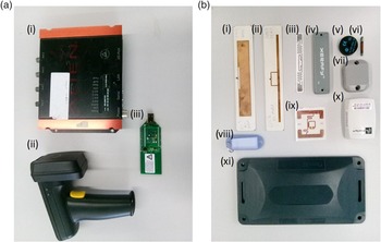
The RFID reader (or interrogator) transmits and receives radio waves to communicate with RFID tags. The reader is connected internally or externally to one or more antennas, which emit radio waves and receive signals back from tags. With respect to their functionality, the readers can be either active or passive, while they operate in the same frequency bands with the tags (LF, HF, UHF, SHF). In Figure 2 a selection of RFID readers and tags is presented. It is interesting to note that tags of the same classification can have very different sizes and forms.
A selection of RFID readers (a) and RFID tags (b). In particular, a(i) is a UHF fixed reader, a(ii) a UHF handheld reader and a(iii) an LH reader; b(i), (ii), (iii), (iv), (vii), (ix) are passive UHF tags, where b(iv), b(vii) are also metal mountable, b(v), b(vi) are low-frequency tags and b(x), b(xi) are UHF active tags.

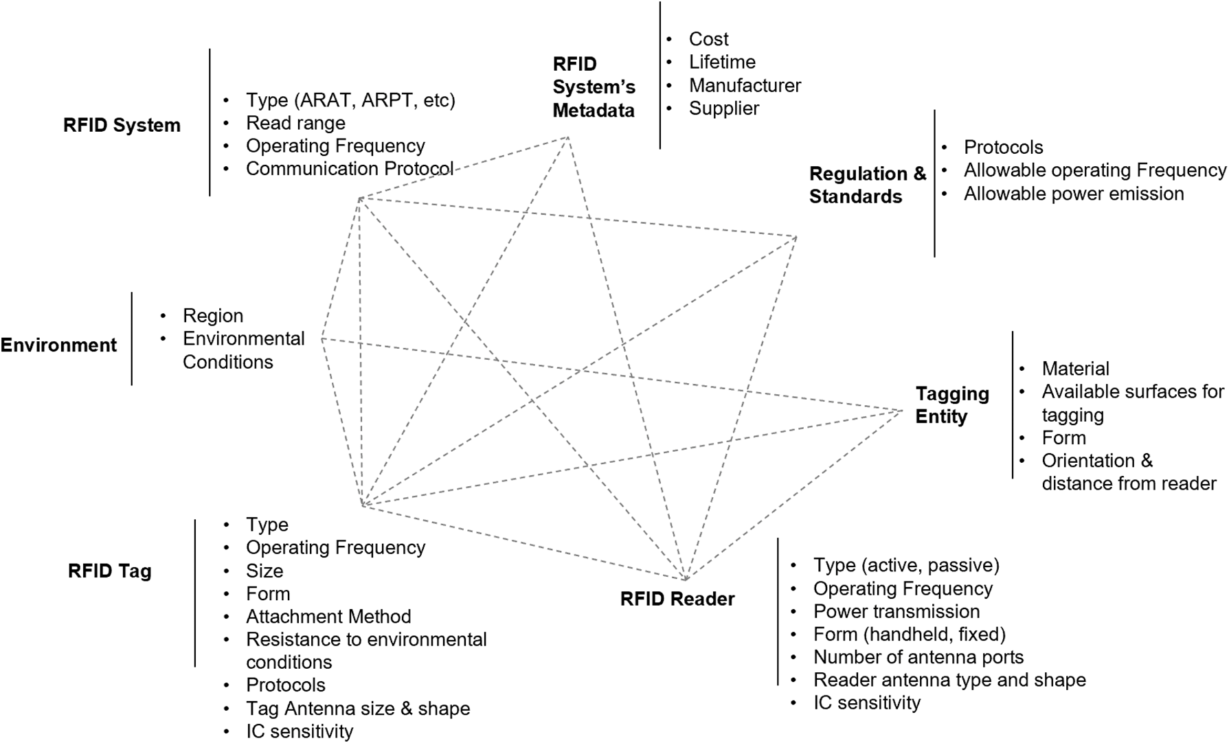
To discern amongst the various types of readers and tags, one has to consider the wide range of interacting factors. For instance, the selection of a tag is determined by the required read range, the type of the reader (as they can only communicate if they operate in the same frequency band), the regulations of the country that it will operate in, the properties of the entity to be tagged, the environmental conditions that it will be exposed to, the required maximum cost and minimum lifetime. These factors and their interrelations are presented in Figure 3.
The factors and their interrelations that the user has to take under consideration to choose the right RFID system/reader/tag.

4 The ontology development process
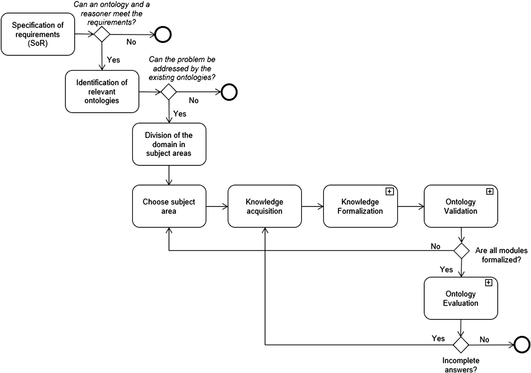
The development process of the RFID SCO was mainly based on the METHONTOLOGY, as defined by Fernández-López et al. (Reference Fernández-López, Gómez-Pérez and Juristo1997) with some modifications. In particular, the methodology followed in this research work is presented in Figure 4.
The UML diagram of the development process of the RFID SCO.

As in METHONTOLOGY, the ontology development process starts with the specification phase, where the purpose and the scope of the ontology are defined. For this purpose, a set of use cases and a set of competency questions with regards to the domain of interest are provided by the domain expert (DE). Then, the ontology engineer identifies the ones (if any) that an ontology-based knowledge-based system can address.
Next, according to the recommended practice and the linked data principles (Burleson et al., Reference Burleson, Gutirrez and Mihindukulasooriya2014), an investigation of any relevant ontologies that are available has to be conducted. If any consistent union of these ontologies can address the competency questions, then it follows that there is no need to proceed any further with the ontology development process. Otherwise, the competency questions are divided into subject areas and the ontology engineer proceeds with the knowledge acquisition process. For this phase, the ontology engineer has to conduct a series of interviews with the DEs in conjunction with research publications, white papers, standards, regulations and any other source of information (e.g., relevant ontologies) from which valuable knowledge can be extracted.
After this stage, the gathered knowledge is formalized. The formal language with which the knowledge is going to be represented has to be decided at this point. The formalization process includes the identification and definition of the classes and properties and the formulation of the axioms. Once a first version of the ontology has been developed, it is important to ensure that: (i) it does not contain any conflicting information and (ii) it does not affect the external ontologies that have been reused. Then, the ontology will be evaluated by performing the competency questions over the ontology. If the answers are either wrong or incomplete, then the ontology engineer will have to investigate and fix the reasons for these results by returning to the knowledge acquisition process.
In the following section, the development of the RFID SCO is detailed.
4.1 Specification of requirements for RFID SCO
The purpose of RFID SCO is to aid the identification and configuration of the right RFID system, reader or tag based on the requirements of the end user, who can be either an RFID expert or a non-expert.
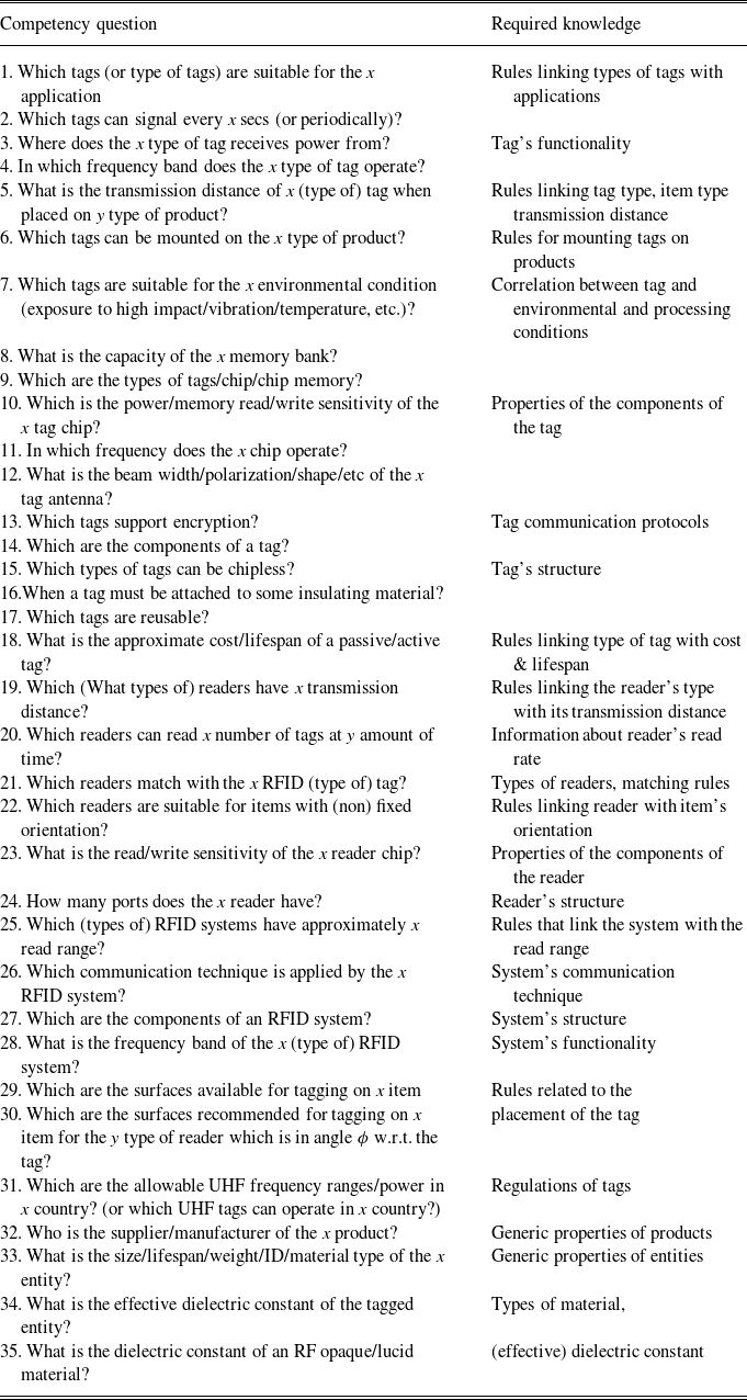
Interviews with DEs have resulted to a set of 35 competency questions, which are presented in Table 1. The first column of the table presents the questions and the second the related knowledge that needs to be captured to address these questions. The questions can be clustered into six groups: questions about the tag (questions 1–18), the reader (questions 19–24), the system (questions 25–28), the regulations (questions 29–30), the placement of the tag to the item (question 31) and the nature of the materials (questions 32–35). Also, there are two different types of questions, that is the questions that only require a set of rules to address them and the questions for which suppliers’ and manufacturers’ datasheets are also required. For instance, with the question ‘Which type of tags are suitable for the far field communication’, which is a specified version of the first question that appears in Table 1, that is which tags are suitable for the
 $ x $
application, the end user will retrieve that the active tags are suited for this case, while with the question ‘Which tags are suitable for the far field communication’, the end user will retrieve the specific active tags included in the respective datasets.
Competency Questions table for the RFID SCO

The two real-world use cases detailed below demonstrate how the competency questions of Table 1 can be applied to identify the most suited (types of) RFID readers and tags.
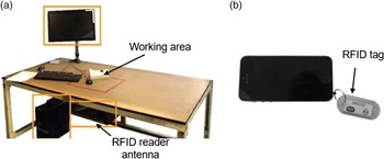
Use case 1. For an end-of-life electronics company (located in the UK) that refurbishes and recycles used electronics, it is of importance to trace products through the different processes that are carried out. Traceability is required to ensure that processes are adhered to (e.g., data erasure, functional testing), in particular when adhering to publically available standard processes (e.g., PAS 141 Quariguasi-Frota-Neto et al., Reference Quariguasi-Frota-Neto, Reade, Dindarian and Gibson2014). The traceability has been achieved using an RFID system where each asset is assigned an ID by attaching an RFID tag to it, and each tag has a different EPC (Electronic Product Code) (Sharpe, Reference Sharpe2016). The processes that are carried out on each product are recorded in a database where each asset is identified by the tag when they are located at each workstation, see Figure 5(a). A UHF (Ultra High Frequency) system was selected as the tag can be read up to 2 m away from the reader. The RFID tags are only required to be on the assets when there are within the refurbishing/recycling process, so to minimize cost it was required that the tags to be reusable. There are numerous RFID tags with adhesive backing which can easily be attached to an asset, but they are difficult to remove without causing damage to the tag. Furthermore, due to the range of mobile phones being made of different materials, some phones would require an RFID tag capable of operating when attached directly to metal which would lead to additional costs. Therefore, it was decided to use a key fob with a serial port plug attached to it, see Figure 5(b), as this can be used for most mobile phones, is reusable and separates the RFID tag from the phone. The RFID tag chosen was the Alien Glint tag (Alien Technology Corporation, 2016) (27 mm
 $\times$
9.7 mm) as it is of low cost, meets the required read range and has dimensions that fit within a standard sized key fob (54 mm
 $\times$
29 mm).
End-of-life electronics use case; (a) workstation; and (b) detachable RFID tag on mobile phone.

Supposing that
 $l \times h \times w$
is the size of the asset, the following questions result from Use Case 1:
-
1. Which readers have transmission distances within the range of 2 m and can operate in the UK?
-
2. Which types of tags are of low cost value and have transmission distance within the range of 2 m?
-
3. In which form must a tag be to be reusable?
-
4. Which tags have size less than
 $l \times h \times w$
, have transmission distance within the range of 2 m, are reusable and can operate in the UK?

The first question is a conjunction of question 19 and 31 in Table 1; the second question is a conjunction of question 5 and 18; the third question coincides with question 17, and the fourth question is a conjunction of questions 5, 17, 31 and 33.
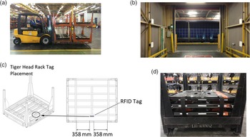
Use case 2. The use of an RFID system to trace metal racks and plastic separators used for carrying items (i.e., crankshafts, cylinder heads, cylinder blocks, camshafts) around an automotive factory (located in the UK) was investigated. The racks and separators need to be monitored as they enter and exit through different locations in the factory. When the racks are carried around the factory they are stacked in pairs up to a maximum of four per forklift as can be seen in Figure 6(a). It was required that multiple tags could be read at a time and at distances up to 5 m so a UHF (Ultra High Frequency) passive RFID system was chosen. To be able to trace the racks and separators as they enter and leave different gateways, the RFID reader antennas were setup as portals at the entrances to doorways, see Figure 6(b). The tag used for tracking the steel racks was the metal-mountable Omni-ID EXO 2000 RFID tag (Omni-ID Ltd., 2017) positioned as shown in Figure 6(c). This tag was chosen as it has a reported read range of up to 20 m on metal and a high impact resistance. For the separators, the Alien technology squiggle tag (Alien Technology Corporation 2017a) was used as this is a tag of low cost that has a maximum read range of 10 m when placed on non-metallic items.
Automotive industry RFID use case; (a) Forklift carrying racks and separator; (b) RFID portal setup at factory door; (c) RFID tag placement on rack; and (d) RFID tag placement on separators.

Supposing that
 $l \times h$
and
 $l' \times h'$
are the sizes of the surfaces available for tagging on the rack and the separator, respectively. The following questions result from Use Case 2:
-
1. Which readers can read multiple tags at a time, have transmission distance within the range of 5 m and can operate in the UK?
-
2. Which types of tags are of low cost and have transmission distances within the range of 5 m?
-
3. Which tags are of low cost, are metal mountable, have transmission distances within the range of 5 m when mounted on metal, have high impact resistance, have size less than
$l \times h$
and can operate in the UK ? -
4. Which tags are of low cost, have transmission distances within the range of 5 m, have size less than
$l' \times h'$
and can operate in the UK?


Clearly, the two use cases outlined above are based on similar kinds of questions. The only additional competency questions that are used in Use Case 2 are the 6th and the 20th (see Table 1) associated with mounting and multiple read capabilities, respectively.
4.2 Identification of RFID-related ontologies
The purpose of this section is to highlight any ontologies in the literature that can potentially address the competency questions presented in Section 4.1. As it is already noted in Section 2, the only two existing RFID-related ontologies are in a preliminary state and are not publicly available. Hence, the RFID SCO had to be developed from the first principle.
4.3 Subject areas and knowledge acquisition
The main subject areas, as determined by the competency questions presented in Table 1 are the following:
-
• RFID Tag: types, applications, structure, properties of the components, functionality.
-
• RFID Reader: types, applications, structure, properties of the components, functionality.
-
• RFID System: types, applications, structure, properties.
-
• Standards and Regulations (S & R).
-
• Placement of tag.
-
• Properties of materials.
It is important to note that these subject areas are highly interrelated. For instance, to exploit the full potential of an RFID system, the placement of the tag on an item depends both on the type of the reader and the type of the tag. Hence, the nexts steps of the ontology development process could not be performed in a strictly linear way.
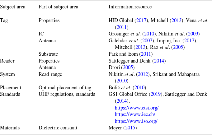
Primarly, the core RFID-related knowledge, such as the types of the RFID systems, readers and tags, the properties of the components and their functionality, was obtained from interviews with DEs. At the same time, external sources of information, such as journal papers and white papers, were consulted to accomplish the required level of accuracy. The information resources per subject area that were used for the development of the RFID SCO are presented in Table 2.
Information resources used for the knowledge acquision process of the RFID SCO

Finally, for the informal definition of the terms appearing in the RFID SCO, the glossaries from the RFID JournalFootnote 2 and Impinj, Inc.Footnote 3 were used.
4.4 Knowledge formalization
In this section the RFID SCO is presented. The aim is to provide machine-understandable content, which can be shared and processed both by automated tools, such as search engines, and by humans. Ontologies facilitate this task by providing a vocabulary of terms, which are core to the domain of interest and some specification of their meaning. This includes the definitions of these terms along with the description of their interrelations, ‘which collectively impose a structure on the domain and constrain the possible interpretations of the terms’ (Uschold, Reference Uschold1998). These termninological formalisms, often called axioms, can be used to impose contraints on the entities described in the terminology. The way that the axioms can be formally expressed is determined by the ontology language used.
Over the years, a wide range of formal languages have been used for ontology development (Common Logic (ISO/IEC 24707:2007), KL-ONE Brachman & Schmolze, Reference Brachman and Schmolze1989, DAML + OIL Horrocks, Reference Horrocks2002, OWL McGuinness et al., Reference McGuinness and Van Harmelen2004, etc.). In this research work the ontology language OWL DL (Grau et al., Reference Grau, Horrocks, Motik, Parsia, Patel-Schneider and Sattler2008) is employed, which is a Description Logic-based language and a decidable fragment of OWL. As OWL, it is endorsed by the World Wide Web Consortium (W3C). OWL DL provides a rich, flexible, decidable modelling language with unambiguous, standardized, semantics, which can be processed by a variety of tools that can be used for developing, validating, integrating and reasoning. Additionally, the data that are already in RDFFootnote 4 (Resource Description Framework) format can be stored directly in highly scalable RDF triple stores and queried in conjunction with the available ontologies to infer implicit information. Data in other formats can be accessed and queried by following the Ontology-Based Data Access (OBDA) approach (Calvanese et al., Reference Calvanese, Giese, Haase, Horrocks, Hubauer, Ioannidis, Jiménez-Ruiz, Kharlamov, Kllapi, Klüwer, Koubarakis, Lamparter, Möller, Neuenstadt, Nordtveit, Özcep, Rodriguez-Muro, Roshchin, Savo, Schmidt, Soylu, Waaler and Zheleznyakov2013).
Formally, in an ontology, ‘the vocabulary of terms’, that is the abstract groups, sets or collections of objects, is represented by the (atomic) classes; the real-world concrete objects are represented by the individuals and the (atomic) properties are used to relate objects either to objects (object properties) or to data values (data properties). For instance, in the domain of RFID systems, the classes
 $\textsf{RFID System}$
,
 $\textsf{RFID Reader}$
,
 $\textsf{RFID Tag}$
can be used to group the various individuals that refer to actual real-world RFID systems, readers and tags, respectivelly. Additionally, the object properties hasReader and hasTag can be used to connect a specific RFID system with a specific reader and a tag, while the property hasId can be used to attribute each one of these entities with an identification code of a string value.
For a more elaborate description of the domain of interest, expressions that are built from atomic classes and atomic properties can be constructed by using the concept and role constructors provided by OWL 2 (Grau et al., Reference Grau, Horrocks, Motik, Parsia, Patel-Schneider and Sattler2008). For instance, the following expression describes the class of individuals that receive power from a batteryFootnote 5:
 \begin{equation*} receivesPowerFrom \, \, \textsf{some}\,\, \textsf{Battery}\end{equation*}
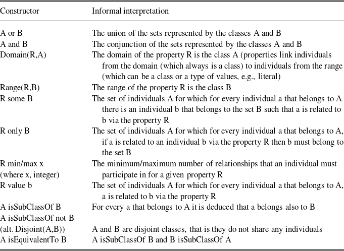
In the Manchester syntax, the taxonomic constructor SubClassOf is used for the class axioms. For instance, with the axiom:
 \begin{equation*}\textsf{Active RFID Tag} \, \, \textsf{SubClassOf} \, \, receivesPowerFrom \,\,\textsf{some}\,\, \textsf{Battery}\end{equation*}
it is expressed that every active RFID tag must receive power from a battery. As it is clear from the notation used, the class
 $\textsf{Active RFID Tag}$
is subclass of the class
 $receivesPowerFrom \, \, \textsf{some}\,\, \textsf{Battery}$
. It is important to note that, in general for ontologies, a subclass always inherits the properties of its superclasses. The full Manchester syntax is presented in Table 3.
The Manchester Syntax and the informal interpretation of its constructors

By using different types of constructors (e.g., the constructors
 $\textsf{min}$
 $\textsf{and}$
 $\textsf{only}$
,
 $\textsf{some}$
,
 $\textsf{value}$
), one can define more complex class axioms. In the same manner, property axioms can also be defined, while properties can also be attributed with further characteristics. For instance, it can be formally stated that a property can be symmetric, functional or transitive.
To capture non-tree-like axioms (Motik et al., Reference Motik, Sattler and Studer2005), such as ‘all reader antennas that communicate with a tag antenna receive the trasmission backscattered from that tag antenna’ the Semantic Web Rule Language (SWRL) (Horrocks et al., Reference Horrocks, Patel-Schneider, Boley, Tabet, Grosof and Dean2004) is also adopted. SWRL rules have the form of an implication between and antecedent and a consequent. The aforementioned statement can be expressed formally in SWRL as follows:
 \begin{align*}&TagAntenna(x)\,\,\wedge \,\,ReaderAntenna(y)\,\,\wedge communicatesWith(x,y)\,\,\wedge \,\,backscatters(x,z)\\ &\quad \rightarrow\,\,receives(y,z)\end{align*}
An additional beneficial property of the SWRL, which is highly exploited in this research work, is that it is equipped with the
 $\textsf{swrlb}$
build-in that allows the performance of mathematical operations (e.g.,
 $\textsf{add}$
,
 $\textsf{lessThan}$
,
 $\textsf{greaterThan}$
).
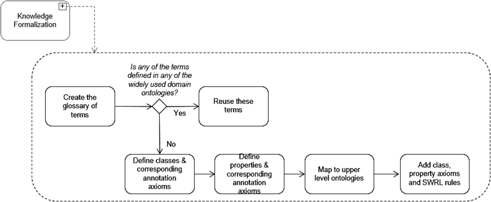
4.4.1 The glossary of terms
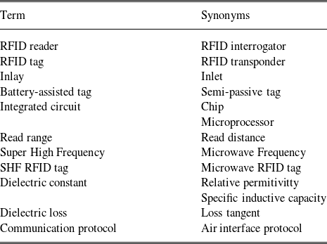
As it is presented in Figure 7, the first step towards the knowledge formalization process is to identify the glossary of terms, that is the set of terms, with their definitions, which are necessary for the ontology. As the final ontology contains overall 264 classes, for brevity, the only part of the glossary of terms that is presented in this section includes the synonyms appearing in the RFID domain and is presented in Table 4. The rest of the terminology is availabe onlineFootnote 6 as part of the ontology. Before proceeding with the formal representation of these terms, it has to be checked that they are not defined in other ontologies. As it is mentioned in Section 2, only two RFID-related ontologies exist in the literature, which, however, are not publicly available and they do not provide any formal definition of the terms used. The only external domain ontology that has been used, is the Environment OntologyFootnote 7, for the representation of the region and the features of the environment that the RFID system operates in.
The RFID SCO development process.

The terms used in the ontology and their synonyms as they are defined in the glossary of terms by the RFID Journal

4.4.2 Definition of classes, properties and axioms
The RFID SCO ontology was developed in a middle-out manner: first, the main terms of the glossary were identified and then the specialization and generalization of these terms followed. The terms of the RFID SCO were mapped to an upper level (i.e., domain independent) ontology to enhance its semantic interoperability and to act as a foundation for its development. To this end, the Basic Formal Ontology (BFO) (Arp et al., Reference Arp, Smith and Spear2015) was used, as it is one of the most widely used upper level ontologies; more than 250 ontologies are based on the BFOFootnote 8. The mapping of the RFID SCO to BFO is omitted for brevity, but can be found in the ontologyFootnote 6.
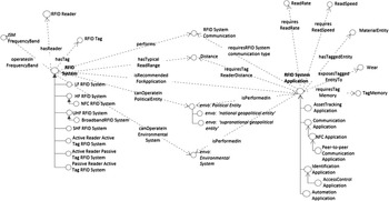
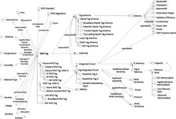
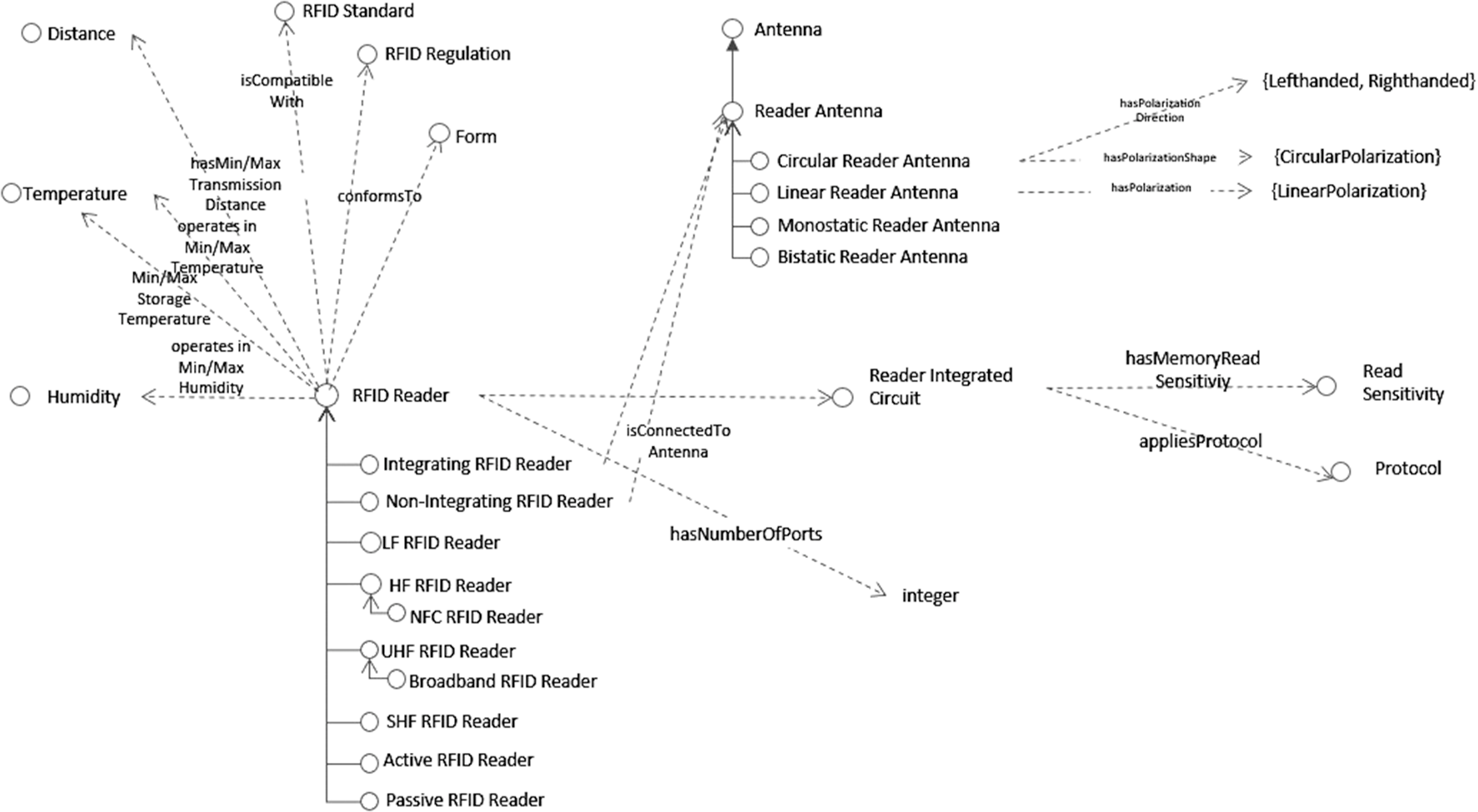
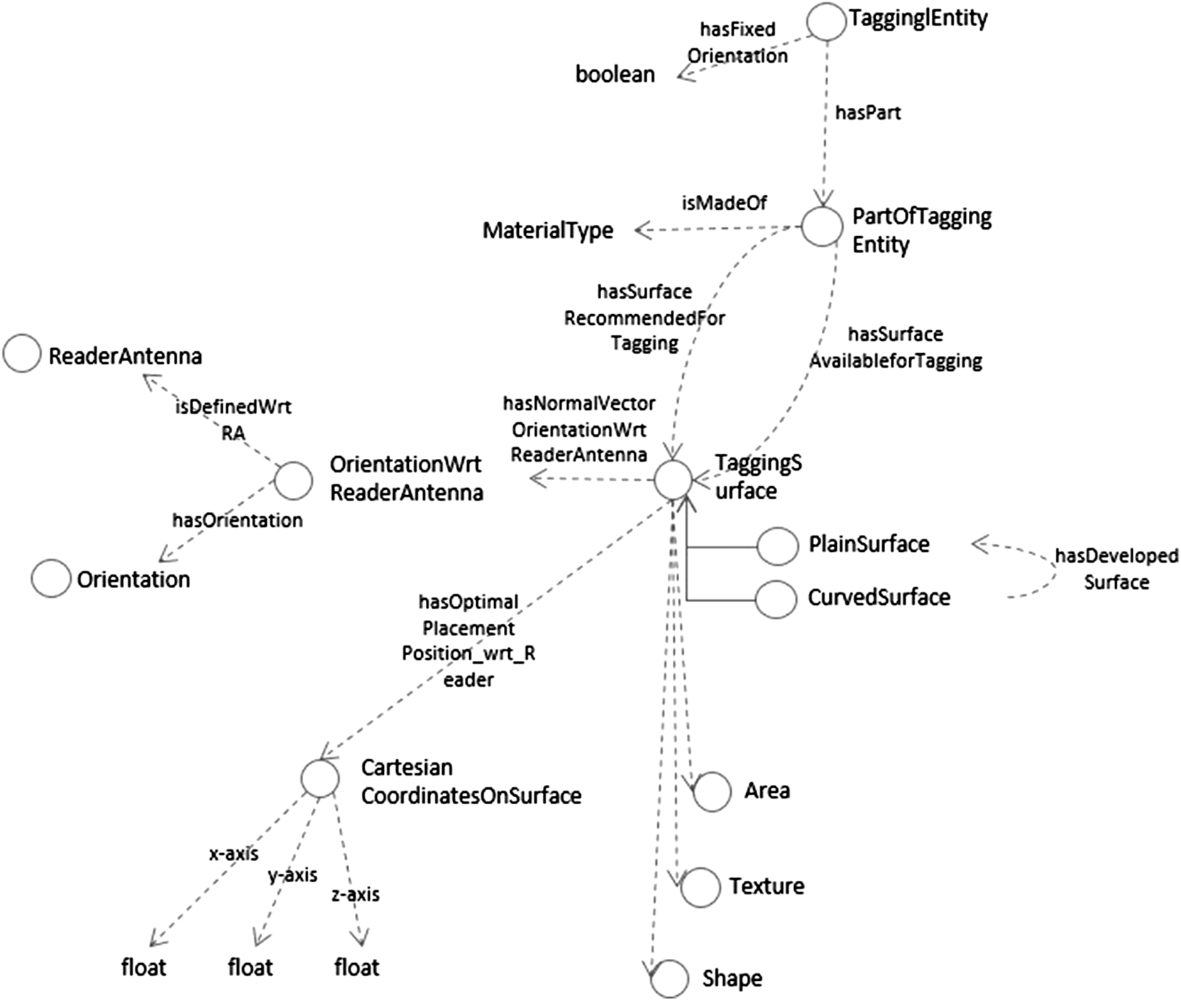
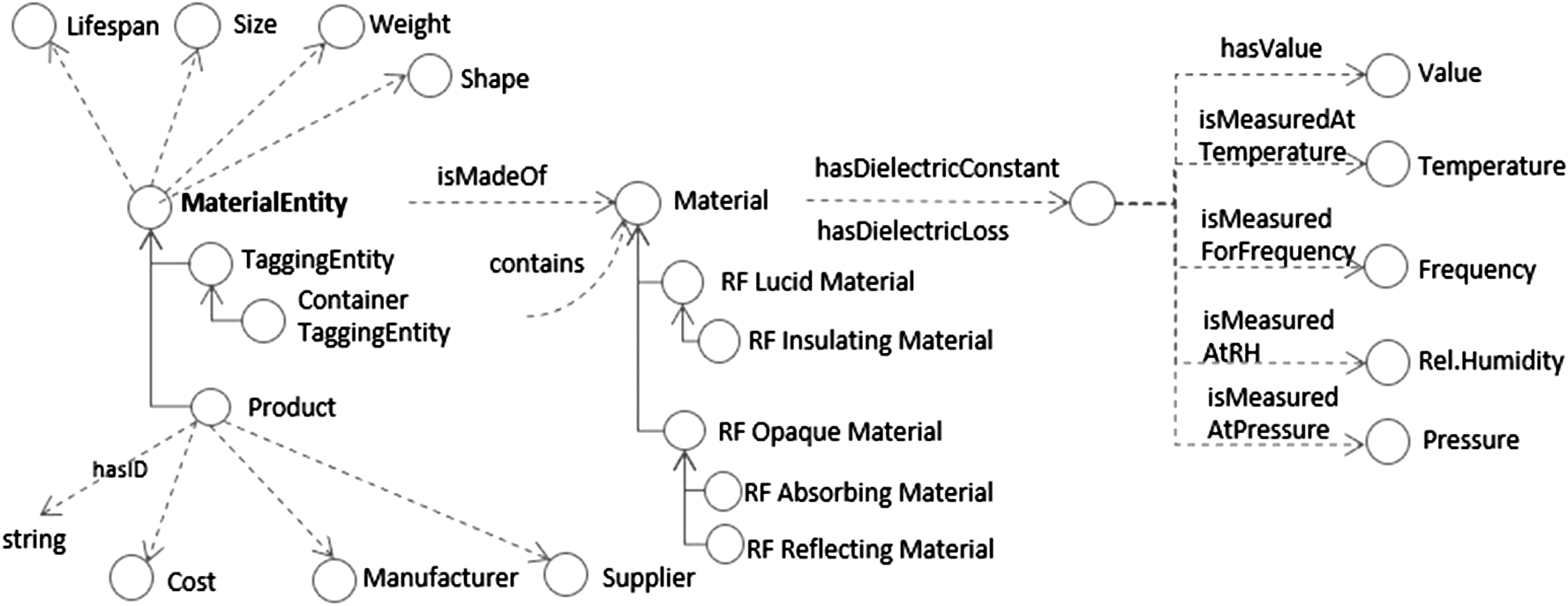
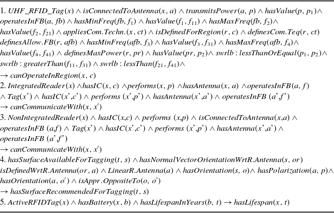
The graphical representation of the main classes, properties and subclass relationships of RFID SCO is presented in Figures 8, 9, 10, 11 and 12. In all graphs, the classes are represented with a circle while the data values presented only with the type of the value. Additionally, the arrows with solid lines represent the SubClassOf relationships and the dashed arrows the (object or data) properties. For visual clarity, the labels of the object property arrows that link a class A to a class B with name ‘hasB’ are omitted. Also, for brevity only a small subset of the 604 OWL DL and SWRL axioms contained in the ontology is presented in Tables 5 and 6. Next, the main classes of RFID SCO are described.
Excerpt of the RFID SCO about the RFID system

Excerpt of the RFID SCO related to the RFID tag types and properties.

Excerpt of the RFID SCO that is about the RFID readers types and properties.

Excerpt of the RFID SCO that is about the placement of the tag on the tagging entity.

Excerpt of the RFID SCO that is about the properties of the material entities.

Subset of OWL axioms appearing in RFID SCO

Subset of SWRL axioms appearing in RFID SCO

RFID System. The various types of RFID systems, as they are descibed in Section 3, are presented in Figure 8 along with their properties (e.g., structure, read range, operating frequency, type of communication). Besides the SubClassOf relationships that appear in Figure 8, the ontology is also enriched with the formal definitions of each one of these concepts. For instance, the several types of communications, and their differencies are explicitly formally defined in the ontology. The RFID systems are classified in RFID SCO according to their operating ISM frequency band and to their functionality. Also, peripheral knowledge that is pertinent to their performance and operation, such as the environmental system and the region that operate in, is also presented formally in the RFID SCO, as it is presented in Figure 8. For these concepts the classes
 $\textsf{Enviromental}$
 $\textsf{System}$
and
 $\textsf{Political}$
 $\textsf{Entity}$
from the ENVO ontology were used.
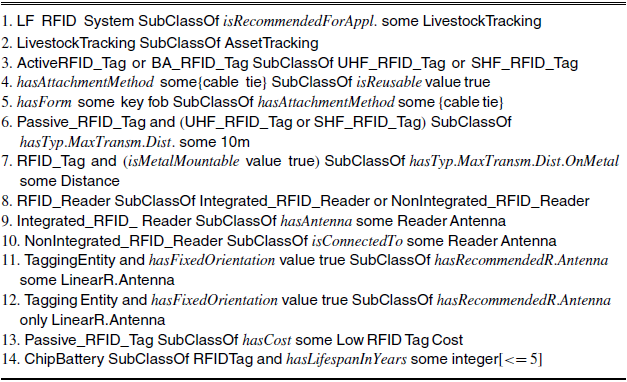
According to Sattlegger and Denk (Reference Sattlegger and Denk2014), specific types of RFID systems are recommended for specific RFID applications: LF RFID systems are used for tracking livestock and pets, access control and waste management; HF systems for smart tickets, for tracking books, for passports, assets and tools; UHF systems with passive tags for retail, asset or inventory management, waste management and access control; UHF with active tags for toll collection, fleet management, logistics container tracking and asset or inventory management. These rules are formally presented in the ontology. For instance, with the first two rules of Table 5, it is expressed formally that LF RFID systems are recommended for livestock tracking, which is a type of asset tracking.
However, for a more precise selection of the most suitable RFID system, the requirements of the specific application must be fulfilled by the properties of the respective RFID system. Hence, the read rate, read speed, tag memory, that an RFID system application requires are also included in the ontology. Also, as the characteristics of the material entity to be tagged (e.g., size, shape, texture, material) are critical for the choice of the right RFID system, they are represented through the
 $\textsf{MaterialEntity}$
class (Figures 8, 12). Additionally, different types of applications require the performance of different types of communication (and hence the application of the respective protocol). For instance, long-range applications, like toll payment, require far-field communication types, while short range applications, like card payment, require near-field type of communication. These rules are also expressed formally in the RFID SCO.
RFID Tag. In RFID SCO, the classification of RFID tags is based on their structure, operating frequency and functionality. Hence, they are classified as
 $\textsf{Chipless}$
tags and as tags with chip (
 $\textsf{RFID Tag with IC}$
), as LF, HF, UHF, SHF RFID tags and as active, passive and battery-assisted tags. The functional and structural differences amongst the tags, as mentioned in Section 3, are represented in the ontology with formal rules. For visual clarity, only the structural differences (i.e., that only the active and the battery-assisted tags have batteries) are depicted in the graph of Figure 9. As it is shown in Figure 9, the chipless, the LF and HF tags can only be passive. Subsequently, the active and battery-assisted tags can only be UHF or SHF. This is expressed in OWL DL with the third rule of Table 5.
RFID tags can have various forms: for example, inlay, label, card, badge, hard tag, etc., which are presented in the ontology as instances of the
 $\textsf{TagForm}$
class. The attachment method to the item to be tagged is represented with the class
 $\textsf{Attachment Method}$
, which has as subclasses the
 $\textsf{Embedding }$
,
 $\textsf{Mounting }$
and
 $\textsf{Hanging}$
attachment methods. The
 $\textsf{Mounting }$
has instances of the different types of mounting, such as
 $\textsf{epoxy}$
,
 $\textsf{welding}$
,
 $\textsf{straps}$
,
 $\textsf{shring wrap}$
,
 $\textsf{rivet}$
,
 $\textsf{general purpose adhesive}$
, while the class
 $\textsf{Hanging}$
has the
 $\textsf{cabletie}$
as instance. The reusability of the tag relies on the type of the attachment method. In particular, if it is attached either by rivets, screws and bolts, shrink wraps, straps or cable tie attachments then it is reusable. Hence, for the case of cable tie, this is expressed in OWL DL with the fourth rule of Table 5. Similar axioms are included in RFID SCO for the rest of the attachment methods. Additionally, in some cases, the form of the tag dictates the attachment method. For instance, as it is expressed with the fifth rule of Table 5, if it is in the form of a key fob then, the attachment method is cable tie. Hence, from the fouth and fifth rules, it is easily inferred that if a tag is in key fob form then it is reusable.
Besides the resistance of the tag to harsh conditions, which is represented with the
 $\textsf{Wear}$
class in Figure 9, there are cases where it has to be resistant to extreme environmental conditions (e.g., temperature, pressure, humidity) as well. Therefore, the operating and storage minimum and maximun temperature/humidity properties are also included in the ontology. Also, RFID tags are equipped with the ingress protection data property, which shows with an integer number the degree of protection from intrusion, dust, accidental contact and water (HID Global, Reference Global2017). The ATEX certified property is used to represent whether a tag is approved for use in environments with explosive atmosphere (HID Global, Reference Global2017). With the property resistance To Chemicals the chemicals to which a tag can be safely exposed are expressed. Finally, the UV resistance property is used to express the resistance of the tag to ultraviolet waves, which is particularly important for tags with printed information that may be used outdoors for long periods of their lifecycles.
Every tag has to be compatible with some international standard (and therefore also with the protocols and communication techniques of that standard) and must conform to the regulations of the country that it will operate in. Also, as mentioned in Section 3, tags have some typical transmission distances, which are typically defined based on the operating frequency band of their antennas. As an example, the case of passive UHF or SHF tags is represented with the sixth rule of Table 5, where the distance value ‘10 m’ is further analyzed to: ‘10 m hasValue 10’, hasUnit ‘meter’ in the RFID SCO. However, as in the case of RFID systems, the actual transmission distance of the tag depends on a set of parameters ranging from the physical characteristics (e.g., material, size) of the tagged entity to the environmental conditions under which it operates. As metallic items affect greatly the performance of UHF and SHF tags, a special class of metal mountable tags has been developed, that is of tags that perform better when mounted on metalsFootnote 9. Hence, as it is shown with the seventh rule of Table 5, if a tag is metal mountable then it is also attributed with the property hasTypical Max Transmission Distance On Metal.
As it is shown in Figure 9, the main types of tag antennas are the dipole, loop and patch (Impinj, Inc. 2017). The broadband, meander, T-match and tip loading are types of dipole antennas; the slot is type of patch antenna. Tag antennas inherit the properties of the antenna, that is they are characterized by an impedance, beamwidth, polarization and shape. Also, they transmit power and operate in an ISM frequency band. In contrary to the alternative types of tags, UHF tags can operate in several frequency bands but only few of them are allowable for each country. Hence, a UHF tag conforms to the regulation of a country if the operating frequency and the transmitted power of its antenna are within the allowable limits determined from that country and if the communication technique performed by the tag coincides with that of the respective regulation. This is expressed formally with the first rule of Table 6.
In RFID SCO, three types of RFID chip are defined: the read-only, the read-write and the write-once-read-many. As it is indicated in Figure 9, all three types operate in a frequency band and have some impedance. Also, they have a memory which is devided into memory banks and is characterized by some capacity (IMR). Tag chip memories are equipped with the EPC memory structure. Also, all types of tag have a memory read sensitivity, power sensitivity and they apply some protocol (which complies with the standard). The read-write and the write-once-read-many tags are also equipped with memory write sensitivity. Knowledge of sensitivity and impedance of RFID chips and antennas is critical for design of both tags and readers. As Nikitin et al. (Reference Nikitin, Rao, Martinez and Lam2009) has shown, variations in either chip sensitivity or impedance matching (between the chip and the tag antenna) can change tag’s transmission distance (and hence system’s read range) by about 40%.
RFID Reader. As it is shown in Figure 10, the classification of the RFID readers depends on their structure (i.e., integrated, non-integrated), operating frequency band (i.e., LF, HF, UHF, SHF) and functionality (i.e., passive, active). Every reader can be either integrated or non-integrated, that is it can either have a reader antenna as a part or it can be connected to an external reader antenna. This expressed with rules 8–10 of Table 5. Additionally, readers can be in two different forms: fixed or portable (handheld). Similarly to tags, the knowledge surrounding the environmental conditions (i.e., temperature, humidity) and the regulations under which they can operate, is also included in the RFID SCO. Also, their typical transmission distance is calculated based on their operating frequency and functionality. Specifically for the readers, the knowledge of both, horizontal and vertical, is critical for the estimation of the overall perfomance of the system.
The reader antenna is a subclass of the antenna class, hence it inherits all the properties of this class, for example, beam width, impedance. There are four main types of reader antennas: based on their shape—circular and linear, and based on their functionality—monostatic and bistatic (Drori, Reference Drori2005). The circular antennas have circular polarization while the linear ones have linear polarization. For tags with fixed orientations it is better to use linear antennas (by matching their polarizations), while for tags with unknown orientation circular antennas are recommended, as they can receive equally well for multiple tag orientations, but by loosing at least 3 dB compared to linear antennas (Drori, Reference Drori2005). For the case of fixed orientation, this is expressed formally with the 11th and 12th axioms of Table 5, where the use of both constructors some and only enforces the use of a reader antenna that is only linear. Although, the RF communication could be enabled with a circular antenna as well, such a choice is not preferrable as they have reduced performance. For the case of non-fixed orientation of the tagging entity, the rules are similar.
Finally, the reader’s chip inherits the properties of the Integrated Circuit class (i.e., operates in frequency band, has impedance) and as tag chips, they have a read sensitivity and they apply some protocols (e.g., communication/air interface protocol, data protocol). This information is essential for the identification of the right tag, as the communication between the reader and the tag is established only if they operate in the same frequency and apply the same communication protocol. This is expressed formally with rules 2 and 3 of Table 6.
Placement of Tag. As it is shown in Figure 11, the material of the part of the tagging entity (
 $\textsf{Tagging}$
 $\textsf{Part}$
 $\textsf{Of-}\textsf{Entity}$
) is the main determinant for the placement of the tag. For instance, if this material is metallic, then either metal-mount RFID tags should be preferred or an insulating material should be used between the part and the antenna (for UHF/SHF tags). These are expressed formally in the RFID SCO. The part of the tagging entity that can be tagged has to have at least one surface available for tagging, which can be identified by either an end user or a simulation tool (Neal et al., Reference Neal, Sharpe, Conway and West2019). The set of surfaces recommended for tagging is a subset of the surfaces available for tagging and is determined by the position of the reader antenna. Ideally, the RFID tag should be aligned with the plane of the reader antenna so that the tag absorbs as much RF energy as possible (Bolić et al., Reference Bolić, Athalye and Li2010). To define this formally, the notion of normal vector was used. Hence, if the reader antenna is linear, then a surface recommended for tagging is the one that the orientation of the polarization of the reader antenna is approximately opposite to the orientation of the normal vector of the surface. This is expressed with the fourth rule of Table 6. If the reader antenna has circular polarization, then any available surface for tagging is also recommended for tagging.
Another parameter that is crucial for the choice of the surface of the entity to be tagged is its size. The problem becomes more challenging when the mounting surface is curved. For this case the notion of developed surface is used in RFID SCO. A mounted tag must be flexible and smaller that the area of the developed surface.
Material Entity. The tag, the reader, their components and the reader antenna are products. As such, as it is shown in Figure 12, they are attributed with a manufacturer, a supplier, a cost and an identification number. In general, passive tags have low cost but there are cases where they have high cost as well. For instance, when they are manufactured for bespoke applications in harsh environments (Tribe, Reference Tribe2019). To depict this the class
 $\textsf{RFID Tag Cost}$
is defined with subclasses:
 $\textsf{Low RFID Tag}$
 $\textsf{Cost}$
,
 $\textsf{Medium RFID}$
 $\textsf{Tag Cost}$
,
 $\textsf{High RFID}$
 $\textsf{Tag}$
 $\textsf{Cost}$
(the respective classes exist also for the readers). This way the 13th axiom of Table 5 can be defined.
At the same time, the above subclasses are material entities, hence, they are attributed with some size, weight and a lifespan. This way, for instance, it can be expressed that the lifespan of an active tag coincides with the life span of its chip battery and that the lifespan of a chip battery is five years (rule 5 from Table 6 and rule 14 from Table 5). This way, a non-expert can be provided with the reasons underpinning the short term lifespan of an active tag.
The entities to be tagged (or already tagged), and their content (e.g., liquid), are also material entities, hence they inherit the same properties. Addionally, every material entity is made of some material which has a dielectric constant and a dielectric loss (Meyer, Reference Meyer2015). Both the dielectric loss and the dielectric constant of the antenna, the substrate and the tagging entity are crucial for the efficient design of the tag antenna (Tribe, Reference Tribe2019). Their values are measured at some specific temperature, pressure, frequency and relative humidity. Finally, based on the level of RF transparency, the materials are classified as either RF lucent or RF opaque. An insulating material is RF lucent, for instance, polyurethane foam FR-3703, has dielectric constant 1.08 and dielectric loss 0.00164 at 1 GHz,
 $22^\circ$
C, RH=39%, P=101.6 kPa (Meyer, Reference Meyer2015).
It is important to note that the synonyms appearing in Table 4 are also represented in the ontology as equivalent terms. This way, any of the equivalent terms can be used in a query returning the same answers. For example, users can ask for the cheapest battery-assisted tags or, equivalently, for the cheapest semi-passive tags.
5 Model testing
The model testing checks the ontology with respect to the formal and rhetorical requirements (Peroni, Reference Peroni2016). According to Peroni (Reference Peroni2016), the formal requirement is used to ensure that the ontology is consistent and the rhetorical one to ensure that the motivating scenarios are covered by the ontology. We also extend the formal requirement to include the conservative extension condition (Jiménez-Ruiz et al., Reference Jiménez-Ruiz, Grau, Sattler, Schneider and Llavori2008), which ensures that the original meaning of the reused terms from the external ontologies (in this case ENVO and BFO) is not changed, that is no new inferences are derived over their vocabulary from RFID SCO. Next, we discuss the ontology with respect to the formal requirement and then with respect to the rhetorical one.
5.1 Ontology validation
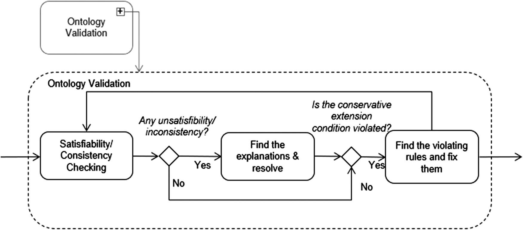
As ontologies are logical schemas, in order to draw robust and reliable conclusions they must be consistent, that is they must not contain any conflicting information. Also, all the properties and classes must be satisfiable (i.e., can be instantiated) (Baader et al. 2003). Depending on the ontological language, various reasoners can be used for consistency checking. For this work, the reasoner Pellet is used as it supports OWL DL ontologies (Sirin et al. 2007). As it is shown in Figure 13, once any inconsistency/unsatisfiability is found, Pellet’s explanation tool is used to trace the set of rules that cause this unsatisfiability and it is resolved accordingly. The RFID SCO ontology is consistent and does not have any unsatisfiable classes or properties.
The UML diagram for the ontology validation.

At the same time, it must be assured that the external ontologies used, BFO and ENVO, are not violated by the RFID SCO ontology. To ensure this, the methodology developed by Jiménez-Ruiz et al. (Reference Jiménez-Ruiz, Grau, Sattler, Schneider and Llavori2008) was followed, which in this case is straightforward as it suffices to ensure that the set of the reused classes is either generalized (e.g., by adding super classes) or refined (e.g., by adding subclasses) but not both. Otherwise, if for instance, the class
 $\textsf{envo:Political}$
 $\textsf{Entity}$
is refined by some RFID SCO class
 $\textsf{A}$
, and the class
 $\textsf{envo:Enviromental}$
 $\textsf{System}$
is generalized by some other RFID SCO class
 $\textsf{B}$
, then there is chance that some unwanted new inference will be derived between the two ENVO classes. However, in our case, both ENVO and BFO are used as upper level ontologies, that is we only refine the reused classes. Hence, the conservative extension condition is ensured.
5.2 Ontology evaluation
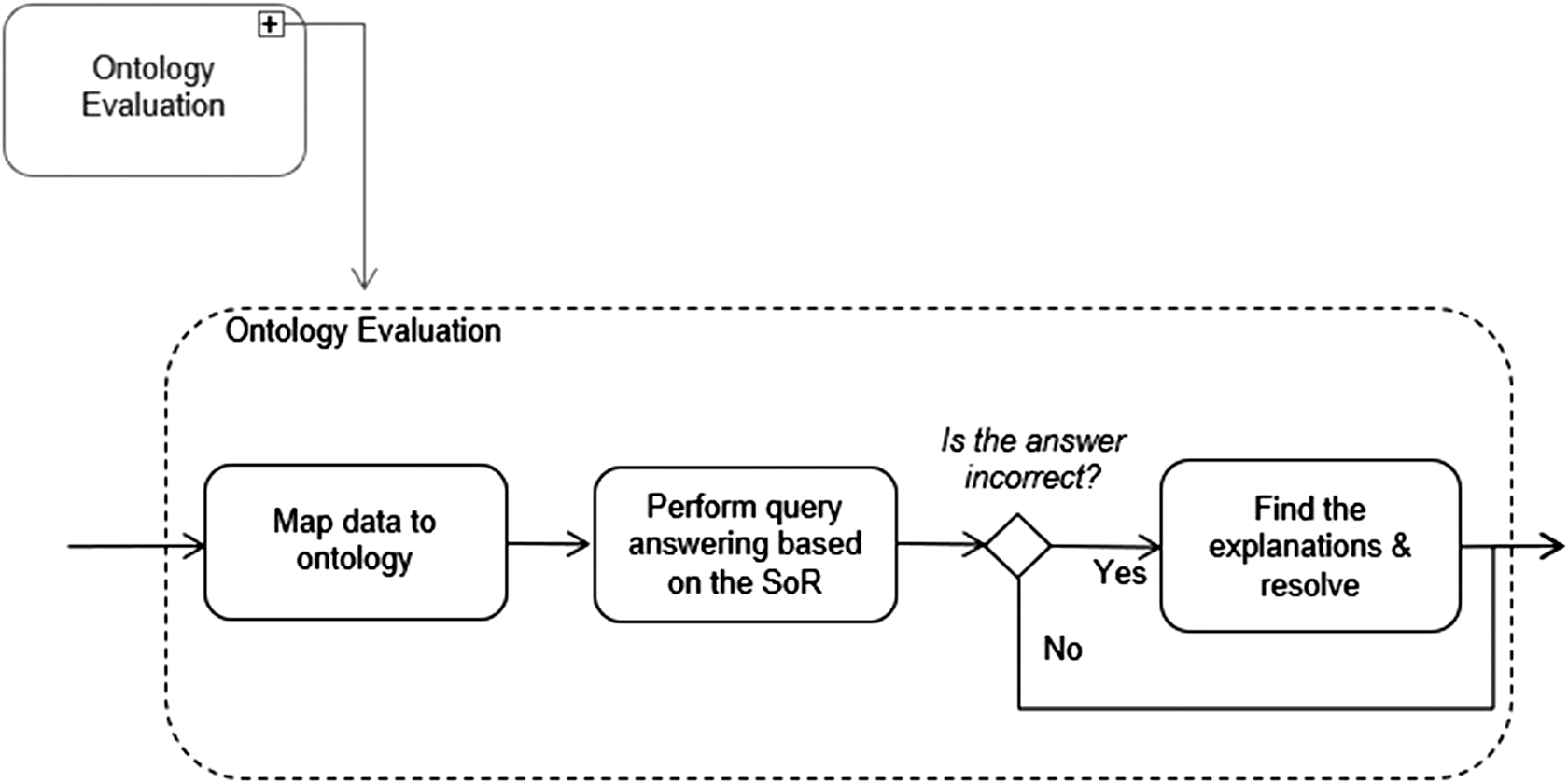
The process followed for the evaluation of the ontology is depicted in Figure 14. First, the ontology is populated manually with a set of data from RFID-related commercial websitesFootnote 10. Then, the ontological knowledge base was tested against the competency questions of Table 1, which were transformed to SPARQL (Sirin & Parsia, Reference Sirin and Parsia2007). To this end, the SNAP SPARQL query editor (Horridge & Musen, Reference Horridge and Musen2015) and the reasoner Pellet (Sirin et al. Reference Sirin and Parsia2007) were used. For the false answers, the explanation tool (Kalyanpur et al., Reference Kalyanpur, Parsia, Horridge, Sirin, Aberer, Choi, Noy, Allemang, Lee, Nixon, Golbeck, Mika, Maynard, Mizoguchi, Schreiber and Cudré-Mauroux2007) provided by Pellet was used to trace the set of rules resulting to these answers. If any conflicting rules were found then they were resolved accordingly, otherwise the error was traced back to the knowledge acquisition process (Figure 4). Next, the answers to the questions resulted from the Use Cases 1 and 2 of Section 4.1 are presented.
The UML diagram for the ontology evaluation.

Regarding the choice of the reader, the following two questions resulted from the two use cases:
-
• Which types of readers have transmission distance within the range of 2 m?
-
• Which readers can read at least two tags at a time, have transmission distance within the range of 5 m and can operate in the UK?
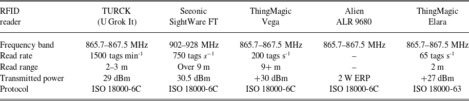
The first question is generic as, theoretically, only the rules of the ontology suffice to answer it. However, there is no set of rules in RFID SCO interlinking the types of readers to some typical transmission distance. Hence, this query cannot be answered by RFID SCO. For the second query, the ontology was populated with data from the data sheets of five realistic RFID readers. The part of the data, as they are obtained from the manufacturers’ data sheets, essential for the part of the evaluation presented in this section are presented in Table 7. It is interesting to note they are not consistent: there are missing data (i.e., the read rate of the Alien ALR 9680) and they are presented with different units (i.e., transmitted power). Unfortunately, due to a lack of any other source of information for the specific readers, only the unit conversion problem was addressed. Before transforming the data to RDF form, the values and units were manually changed to a common unit system. Also, for cases where only a single transmission distance was provided, this distance was allocated as maximum transmission distance.
Parts of the datasheets of the readers used for the evaluation of the ontology

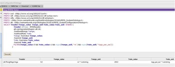
The SPARQL queries and the answers as they are displayed in Protégé (Musen, Reference Musen2015) are presented in Figure 15. From the list of readers appearing in Table 7, only the ThingMagic Vega meets the requirements of the user. The read range of the TURCK and ThingMagic Elara readers is less than 5 m, the Alien ALR’s read range is unknown and, as it is directly inferred from rule 1 from Table 6, Seeonic cannot operate in the UK as its frequency band is outside the allowable frequency band for the UK as it is defined by ETSI (865.5–867.6 MHz and 2 W ERP; 915–921 and 4 W ERP).
The SPARQL query resulted from the question and the answers as they are computed by Pellet.

For the identification of the right tag the following questions resulted from the two use cases:
-
1. Which types of tags are of low cost and have transmission distance within the range of 5 m?
-
2. In which form must a tag be to be reusable?
-
3. Which tags have size less than
$l \times h$
, have transmission distance within the range of 2 m, are reusable and can operate in the UK?
-
4. Which tags are of low cost, are metal mountable, have transmission distance within the range of 5 m when mounted on metal, have high impact resistance, have size less than
$l \times h$
and can operate in the UK ?


Unfortunately, the query editors, Snap SPARQL and DL-Query, supported by Protégé do not support query entailement for complex class expressions. Hence, although evidently the answer to question 1 is the passive and UHF or SHF type of tags, which follows from the rules 6, 13 from Table 5, this cannot be displayed by Protégé. The same also holds for the answer to question 2, which is deduced from rules 4, 5 from Table 5, and it is the key fob.
Supposing that for question 3 the end user is interested to tag a mobile phone of dimensions 158.4
 $\times$
78.1
 $\times$
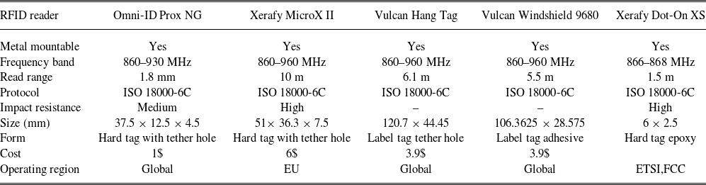
7.5 mm, then the tag is expected to be at least smaller than this. Also, regarding the operating region of the tags, the manufacturing data sheets did not include the transmitted power of the tag, instead, they included the regions in which the tags can operate, which is presented in Table 8.
Parts of the datasheets of the tags used for the evaluation of the ontology

For the question 3 two derivations take place:
-
1. From the information that the tag can operate (globally or in EU), it is inferred that it can also operate in the UK, with the following rules and assertions of the ontology:
\begin{align*}&\textsf{Regulation}\,\,\textsf{isSubClassOf} \,\,isAbout \,\,\textsf{some}\,\,\textsf{envo: political entity}\\ &\quad is About(\textsf{ETSI, EU}), hasPart(\textsf{EU, UK}),\textsf{Regulation(ETSI)},\\ &\quad\,\,\textsf{envo: political entity(EU)} \end{align*}
-
2. As before, from the form of the tag, it is inferred that it is reusable.

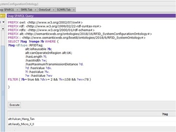
Based on these inferences, as it is shown in Figure 16, Pellet returns the tags Vulcan Hang Tag and Xerafy MicroX II.
The SPARQL query corresponding to question 3 and the answers as they are computed by Pellet.

In similar way, the answer Xerafy MicroX II is returned for the query 4.
6 Conclusions
In this research work, a semantic-based framework that can assist both RFID experts and non-experts to configure and RFID system based on their needs is proposed. For this purpose, semantic technologies have been adopted and, in particular, the novel and publicly available RFID System Configuration Ontology (RFID SCO) has been developed.
RFID SCO is a first effort towards an extensive formal and informal representation of RFID technologies. To accomplish this task, a set of real-world use cases and competency queries have been defined by domain experts. Based on the competency queries, the required knowledge areas and the respective resources of information have been defined. The RFID SCO is developed by reusing terms from the Environment ontology. At the same time, to enhance its semantic interoperability and to establish its structure, it was mapped to the widely used upper level ontology BFO. The RFID SCO was validated and successfully evaluated against the use cases provided by the domain experts.
The dynamic nature of the semantic technologies enables an easy path for expanding the incorporated knowledge. Hence, part of our future work is to extend the ontology with more specific rules with regards to the functionality of the RFID system. Additionally, we plan to exploit linked data techniques to automatically populate the ontology with manafucturers’ and suppliers’ data. Finally, we plan to develop a decision support tool interlinked with simulation tools for the calculation of the estimated read range that not only it will provide the end user with solutions of high precision based on their needs, but it will also provide the underpinning explanations in informal language.
Acknowledgements
This work was supported by the UK Engineering and Physical Sciences Research Council (EPSRC) for Loughborough University (Adaptive informatics for intelligent manufacturing (EP/K014137/1); Embedded Integrated Intelligent Systems for Manufacturing (EP/P027482/1)). The authors would also like to thank Sarogini Grace Pease for her valuable insights on systems’ networks.
Conflicts of interest
The authors declare none.