1 Introduction
Interaction between a streamwise-oriented vortex and a fin, blade or wing has emerged as a critical class of flow–structure interaction, with important consequences for both unsteady and steady loading. Examples include: buffeting of a fin or tail of an aircraft by the vortex originating from an upstream canard; steady and unsteady loading of the downstream blade in a rotating machine arising from the tip vortex generated from an upstream blade; loading of a helicopter rotor due to the tip vortex from a preceding rotor; and alteration of the lift and drag, as well as potential buffeting, of a follower wing due to the streamwise vortex originating from the leader wing in formation flight. This latter type of interaction is not limited to a small number of aircraft and wings of large or moderate scale, but extends to a large number of very small-scale of micro air vehicles in a swarm or flock that may be deployed for atmospheric surveillance (Kroo Reference Kroo2004). In the following, the essential features of the foregoing interactions are summarized.
Vortex interaction with a fin or tail. Interaction of a streamwise-oriented vortex with a fin or tail can involve buffeting, i.e. unsteady loading of its surface. This phenomenon was addressed in the early investigation of Patel & Hancock (Reference Patel and Hancock1974) who employed qualitative visualization to examine the interaction between a streamwise-oriented vortex and both an airfoil and a flat plate. They showed that the incident vortex exhibited breakdown upstream of the plate and tended to re-form on its underside. Quantitative interpretation of the interaction of a broken down vortex with a fin/tail, is provided by Wolfe, Lin & Rockwell (Reference Wolfe, Lin and Rockwell1999) including the effects of time-averaged, apparent partitioning of the vortex on either side of the fin/tail and the consequences for surface pressure fluctuations. Gordnier & Visbal (Reference Gordnier and Visbal1999) revealed, via computations, basic physics of the vortex breakdown–plate interaction, including interpretation of the spectral content of the surface pressure fluctuations in terms of the spiral mode of breakdown. Gursul & Xie (Reference Gursul and Xie2001) examined the relationship between fin oscillation and the breakdown location of an incident vortex; a cutoff frequency of the plate oscillation was defined as the condition for which the location of vortex breakdown remained stationary.
Vortex interaction with a helicopter rotor blade. Interaction of a streamwise-oriented vortex with a helicopter rotor blade was addressed in the investigation of Wittmer & Devenport (Reference Wittmer and Devenport1999). If the vortex does not impinge directly on the leading edge of the blade, but is offset such that it passes along the pressure side of the wing, the core of the incident vortex is not directly affected. As it passes into the wake region, however, rapid decay of the vortex occurs. Furthering investigation into vortex–helicopter blade interactions by Kao et al. (Reference Kao, Ahmad, Holst and Allan2013) defined quantitative patterns of the interaction of vortices from preceding tips of rotors with a given rotor blade in conjunction with the wake vorticity. Raffel, Steelhorst & Willert (Reference Raffel, Steelhorst and Willert1998) defined, on the basis of quantitative experiments, the overall pattern of generation of a tip vortex and its interaction with a given rotor.
Vortex interaction with follower wing. Formation flight involves a vortex from a leader wing that encounters a follower wing. The fundamental physics of the vortex distortion are directly relevant to the foregoing cases of interactions with fins, tails and blades. In the following, it is insightful to summarize the evolution of investigations related to formation flight, which, in turn, can reinforce a more complete understanding of the foregoing classes of interaction.
Hummel (Reference Hummel1983, Reference Hummel1995) calculated the aerodynamic advantages for flocks of birds and aircraft in formation. This was performed by simplifying the wing and its wake as a line vortex, which was represented by a vertical velocity field in the cross-flow plane. The vertical velocity was defined by upwash outside of the wing tips, and downwash inside the tips. By properly locating the follower wing in this wake, it is possible to achieve a significant increase in the lift to drag ratio, as well as a decrease of drag. While this theoretical description shows the importance and overall consequences of tip vortices in formation flight, it does not account for the influence of the downstream (follower) wing on the incident vortex generated from the tip of the upstream (leader) wing and thereby possible alteration of, for example, the swirl ratio, velocity deficit and vorticity components of the incident vortex.
Rockwell (Reference Rockwell1998) provides a review of vortex–body interactions, including the case of a streamwise-oriented vortex. Inasawa, Mori & Asai (Reference Inasawa, Mori and Asai2012) experimentally determined the lift and drag acting on the follower wing, relative to a leader wing, and interpreted these forces in relation to representative cuts of streamwise vorticity. Kless et al. (Reference Kless, Aftosmis, Ning and Nemec2013) performed an inviscid computational study of extended formation flight, with an assessment of different locations of vortex impingement as well as different trim arrangements.
In recent years, Barnes, Visbal & Huang (Reference Barnes, Visbal and Huang2015b ) and Garmann & Visbal (Reference Garmann and Visbal2015c ), as well as in their previous works cited therein, have employed high fidelity computations to extensively investigate many aspects of vortex–wing interaction. These advances provide new insight into the flow physics and the associated unsteady and steady loading of the follower wing; in a more general sense, they also provide further clarification of the underlying physics relevant to the aforementioned streamwise vortex interactions with fins, tails and blades. This series of investigations has addressed the interaction of a streamwise-oriented vortex with a follower wing for the cases of: a spanwise-wandering incident vortex (Garmann & Visbal Reference Garmann and Visbal2014b ); a stationary incident vortex (Garmann & Visbal Reference Garmann and Visbal2014a , Reference Garmann and Visbal2015a ); a stationary NACA 0012 follower wing (as opposed to a flat plate wing) (Garmann & Visbal Reference Garmann and Visbal2015b ); spanwise motion of the follower wing (Garmann & Visbal Reference Garmann and Visbal2015c ); aeroelastic effects of a flexible follower wing along with the effects of vertical position of the incident vortex (Barnes, Visbal & Gordnier Reference Barnes, Visbal and Gordnier2014b ); finite distance between the leader and follower wings (Barnes, Visbal & Gordnier Reference Barnes, Visbal and Gordnier2014a , Reference Barnes, Visbal and Gordnier2015a ); and a follower wing undergoing forced bending (Barnes et al. Reference Barnes, Visbal and Huang2015b ).
For the foregoing aspects of the vortex–wing interaction, Q-criterion (constant values of the second invariant of the velocity gradient tensor) iso-surfaces (iso-Q) of the incident vortex along the wing were characterized in conjunction with the altered vortex of opposite sign vorticity from the tip of the follower wing, separation phenomena along the wing and the overall loading on the wing. Most relevant to our present considerations is the work of Garmann & Visbal (Reference Garmann and Visbal2014a , Reference Garmann and Visbal2015a ), which demonstrates that when the incident vortex is located inboard of the tip of the wing, iso-Q patterns indicate both detectable distortion and vertical inclination upstream of the leading edge.
For these cases, a spiral distortion, which twists in the opposite sense of rotation as the vortex, is present in the iso-surfaces of the Q-criterion. As the vortex approaches the leading edge, it is reoriented from streamwise to plate normal, at which point it alternates between the top and bottom of the plate. Moreover, Barnes et al. (Reference Barnes, Visbal and Gordnier2014a
, Reference Barnes, Visbal and Huang2015b
) examined effects of the swirl ratio
 $q$
, where
 $q=\unicode[STIX]{x1D6E4}/(2\unicode[STIX]{x03C0}r\unicode[STIX]{x0394}u)\approx 1.567u_{\unicode[STIX]{x1D703}}/\unicode[STIX]{x0394}u$
according to Jacquin & Pantano (Reference Jacquin and Pantano2002), in which
 $\unicode[STIX]{x1D6E4}$
is circulation,
 $r$
is the vortex radius,
 $\unicode[STIX]{x0394}u$
is the velocity deficit in the core and
 $u_{\unicode[STIX]{x1D703}}$
is the maximum azimuthal velocity. They showed that the swirl ratio of the impinging vortex is affected by the follower wing; furthermore, the dependence of swirl ratio on the spanwise impingement location of the incident vortex relative to the tip of the wing is shown by Garmann & Visbal (Reference Garmann and Visbal2015a
). It was possible to attain low values of swirl ratio lying below the stability criterion of
 $q\geqslant \sqrt{2}$
corresponding to amplification of small-wavelength perturbations defined by Leibovich & Stewartson (Reference Leibovich and Stewartson1983). Barnes et al. (Reference Barnes, Visbal and Gordnier2014a
, Reference Barnes, Visbal and Huang2015b
) show that these changes in swirl ratio are due to changes in the axial pressure gradient. Barnes et al. (Reference Barnes, Visbal and Gordnier2014a
, Reference Barnes, Visbal and Huang2015b
) revealed that directly upstream of the leading edge, an adverse pressure gradient is present, but outside of the wing tip, Garmann & Visbal (Reference Garmann and Visbal2015a
) showed that the pressure gradient is favourable. The extent of the upstream influence of the follower wing on the incident vortex is addressed in Barnes et al. (Reference Barnes, Visbal and Gordnier2014a
, Reference Barnes, Visbal and Huang2015b
), which states that the axial velocity deficit is enhanced due to the presence of an adverse pressure gradient; it extends approximately one chord upstream of the leading edge of the follower wing.
The theoretical work of Batchelor (Reference Batchelor1964) provides the interrelationship between the azimuthal and axial components of velocity and the pressure gradient. A decrease in azimuthal velocity leads to an adverse axial pressure gradient, which in turn causes an increase in axial velocity deficit. To date, interpretation of the internal structure of the vortex on this basis has not been addressed using experiments or computations.
The foregoing advances provide a basis for gaining new insight into the internal structure of the vortex incident upon the follower wing and the manner in which it is altered in upstream regions. In particular, the heretofore unclarified relationships between the deficit of the streamwise velocity, the magnitudes of streamwise and azimuthal vorticity, the upwash and downwash, the root-mean-square of the velocity and vorticity fluctuations and the swirl ratio will be addressed in relation to the degree that the tip of the follower wing penetrates the incident vortex.
2 Experimental systems and techniques
A free-surface water channel was used for experiments, where the water channel had a test section with a length of 4877 mm, a width of 927 mm and a depth of 610 mm. The free stream velocity was
 $U_{\infty }=158~\text{mm}~\text{s}^{-1}$
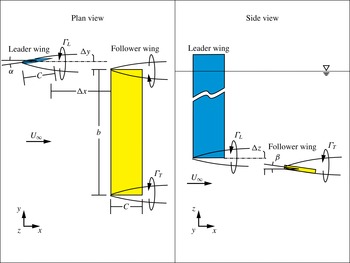
, which corresponded to a Reynolds number of 8000 based on the wing chord. The turbulence intensity was 0.3 %. The experimental set-up is shown in figure 1. The leader wing is a squared tip NACA 0012 airfoil which has chord
 $C=50.8$
mm, angle of attack
 $\unicode[STIX]{x1D6FC}=16^{\circ }$
and is oriented vertically. This angle of attack was selected to generate a tip vortex having a dimensionless circulation similar to that in the computations of Garmann & Visbal (Reference Garmann and Visbal2014a
, Reference Garmann and Visbal2015a
). The follower wing is a clear acrylic flat plate with chord
 $C=50.8$
mm, thickness
 $t=1.58$
mm, span
 $b=203.2$
mm and angle of attack
 $\unicode[STIX]{x1D6FD}=4^{\circ }$
. The streamwise distance between the two wings is
 $\unicode[STIX]{x0394}x=152.4$
mm.
Plan and side views of the experimental arrangement.

The vertical
 $\unicode[STIX]{x0394}z$
and spanwise
 $\unicode[STIX]{x0394}y$
offsets were defined by the trajectory of the tip vortex shed from the leader wing. Preliminary stereo particle image velocimetry (SPIV) images were acquired to determine which values of vertical and spanwise offset led to impingement of the tip vortex from the leader wing on the tip of the follower wing. This location was defined by the leader wing offsets
 $\unicode[STIX]{x0394}y_{0}$
and
 $\unicode[STIX]{x0394}z_{0}$
. In this investigation, four different values of spanwise offset
 $\unicode[STIX]{x0394}y$
were examined,
 $\unicode[STIX]{x0394}y=\unicode[STIX]{x0394}y_{0}+12.7$
mm,
 $\unicode[STIX]{x0394}y_{0}+6.35$
mm,
 $\unicode[STIX]{x0394}y_{0}$
and
 $\unicode[STIX]{x0394}y_{0}-31.75$
mm, while
 $\unicode[STIX]{x0394}z=\unicode[STIX]{x0394}z_{0}$
, i.e. no offset in the vertical direction.
To quantitatively visualize the structure of the vortex, SPIV was employed. It provides all three components of velocity. The flow was seeded with
 $11~\unicode[STIX]{x03BC}\text{m}$
hollow metallic coated plastic spheres, which provide 15–20 particle images in the interrogation window of 32
 $\times$
32 pixels. To illuminate the spheres, a 3 mm thick laser sheet was produced by a dual-pulsed Nd-YAG operating at 14.29 Hz. Images were acquired from each camera simultaneously, where each had a charge-coupled device (CCD) array of
 $1600\times 1200$
pixels. In this SPIV arrangement, the cameras were placed upstream of the laser plane at a
 $40^{\circ }$
angle from the flow, thereby allowing an unobstructed view of the laser plane. The images from the two cameras were then evaluated using a cross-correlation technique with 50 % overlap, yielding 8432 vectors in the field of view. Each pixel was
 $47.36~\unicode[STIX]{x03BC}\text{m}~\text{px}^{-1}$
, which corresponds to an interrogation window width of
 $1515~\unicode[STIX]{x03BC}\text{m}$
.
Both the in- and out-of-plane uncertainties were calculated using the technique described by Adrian & Westerweel (Reference Adrian and Westerweel2011). The root-mean-square (r.m.s.) random error for the in-plane velocity is between 1.0 % and 1.4 % of the free stream velocity, furthermore, the r.m.s. random error is between 1.2 % and 1.6 % of the free stream velocity for the out-of-plane velocity component. For this SPIV set-up, the pixel size is large compared to the particle image diameter and therefore the bias error is small in comparison to the r.m.s. random error.
For each experimental configuration, image acquisition was performed at 6.35 mm intervals from 50.8 mm to 6.35 mm upstream of the leading edge of the follower wing. At each of these locations, 150 images were captured; these images were time averaged to produce the final images. The flow structure at different streamwise locations was examined by translating the wing system to the desired location in the streamwise direction. The leader wing could move independently from the rest of the system, which allowed examination of the flow at successive spanwise locations of the leader wing. At each location, the individual images on the cross-flow planes of the vortex, taken at successive streamwise locations, were combined to provide iso-surface representations of the three-dimensional flow field. These fields contain 67 456 vectors, and allowed calculation of all three components of vorticity.
3 Distortion of vortex structure due to impingement
3.1 Initial structure of undistorted vortex
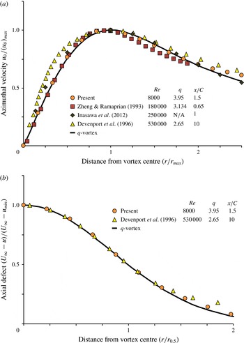
The velocity profiles of the trailing vortex generated from the leader wing, at a location upstream of the region of significant flow distortion as the follower wing is approached, were acquired in the absence of the follower wing and are compared in figure 2 with previous investigations at Reynolds numbers at least an order of magnitude larger than the present study: Devenport et al. (Reference Devenport, Rife, Liapis and Follin1993), Zheng & Ramaprian (Reference Zheng and Ramaprian1993); and Inasawa et al. (Reference Inasawa, Mori and Asai2012). The distribution of normalized azimuthal velocity
 $u_{\unicode[STIX]{x1D703}}/(u_{\unicode[STIX]{x1D703}})_{max}$
is indicated in figure 2(a) and normalized axial velocity deficit
 $(U_{\infty }-u)/(U_{\infty }-u_{min})$
in figure 2(b). For the present experiment, the dimensionless value of maximum azimuthal velocity is
 $u_{\unicode[STIX]{x1D703}}/U_{\infty }=0.49$
, and the maximum axial velocity deficit is
 $\unicode[STIX]{x0394}u=0.19$
. Moreover, the vortex Reynolds number
 $Re_{v}=\unicode[STIX]{x1D6E4}/v$
is 2959. In both figures 2(a,b), the solid line corresponds to the theoretical
 $q$
-vortex described by Garmann & Visbal (Reference Garmann and Visbal2015a
). This
 $q$
-vortex has its origin in the work of Batchelor (Reference Batchelor1964). These normalized distributions of azimuthal and axial velocity have a similar form for all cases, over the range of the Reynolds number based on wing chord from 8000 to 250 000. At the highest value of
 $Re=530\,000$
, there is discernible departure.
(a) Azimuthal velocity
 $u_{\unicode[STIX]{x1D703}}/(u_{\unicode[STIX]{x1D703}})_{max}$
versus
 $r/r_{max}$
in which
 $r_{max}$
is the radial location of the maximum azimuthal velocity
 $(u_{\unicode[STIX]{x1D703}})_{max}$
; and (b) axial velocity deficit
 $(U_{\infty }-u)/(U_{\infty }-u_{min})$
versus
 $r/r_{0.5}$
where
 $u_{min}$
is the deficit velocity at the centreline and
 $r_{0.5}$
is the radius at which the axial velocity deficit is equal to half the maximum deficit. Each profile was created by averaging all available data.

For the present investigation the swirl ratio
 $q=3.95$
, and the value of circulation is
 $\unicode[STIX]{x1D6E4}/CU_{\infty }=0.4$
. This value of
 $q$
lies above the value of
 $q=\sqrt{2}$
corresponding to the onset of azimuthal instabilities (Garmann & Visbal Reference Garmann and Visbal2014a
, Reference Garmann and Visbal2015a
) according to the criterion of Leibovich & Stewartson (Reference Leibovich and Stewartson1983).
3.2 Velocity defect and streamwise vorticity
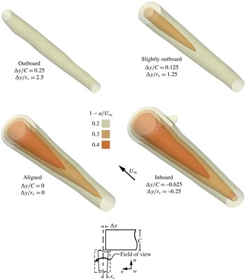
Figure 3 shows iso-surfaces of the streamwise velocity deficit
 $1-u/U_{\infty }$
, hereafter referred to as velocity deficit, along the axis of the vortex incident upon the leading edge of the wing. These surfaces of velocity deficit increase in both radius and magnitude as the spanwise impingement location
 $\unicode[STIX]{x0394}y/r_{v}$
is displaced from outboard to inboard. For all but the outboard case, all levels of iso-surfaces increase in radius near the leading edge of the follower wing.
Iso-surfaces of streamwise velocity deficit
 $1-u/U_{\infty }$
at four spanwise locations
 $\unicode[STIX]{x0394}y/r_{v}$
of vortex impingement. The surfaces extend over the streamwise distance from
 $0.125C$
to
 $1C$
upstream of the leading edge of the wing.

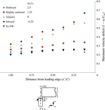
The plot of figure 4 shows the maximum velocity deficit
 $1-u/U_{\infty }$
as a function of distance
 $x^{\prime }/C$
upstream of the leading edge of the wing. For the outboard and slightly outboard positions of the incident vortex,
 $\unicode[STIX]{x0394}y/r_{v}=1.25$
and 2.5, along with the case of no follower wing, there is a mild increase of velocity deficit as the leading edge is approached. Then, in the immediate vicinity of the leading edge, at
 $x^{\prime }/C=0.125$
, a decrease occurs. On the other hand, for the aligned and inboard cases, the velocity deficit increases rapidly as the leading edge is approached. For the case of inboard interaction, the magnitude of the deficit increases by approximately a factor of two from
 $x^{\prime }/C=1$
to
 $x^{\prime }/C=0.125$
. The form of this variation of velocity deficit is detectably distorted relative to the other three variations; such distortion is associated with onset of a large diameter region of high velocity defect that extends well upstream of the leading edge, as indicated in figure 3, as well as relatively large r.m.s. values of velocity and vorticity, which will be addressed subsequently. It is evident from these plots of figure 4, as well as the images shown in figure 3, that the upstream influence of the wing extends at least a distance of one chord
 $C$
, which corresponds to 5 diameters
 $D_{v}$
of the incident vortex in absence of the follower wing.
Plot of the maximum velocity deficit
 $1-u/U_{\infty }$
along the centreline of the vortex for different spanwise locations
 $\unicode[STIX]{x0394}y/r_{v}$
of vortex impingement, as well as for the case of no vortex impingement, i.e. in absence of the follower wing. All cases are plotted as a function of streamwise location
 $x^{\prime }/C$
upstream of the leading edge of the wing.

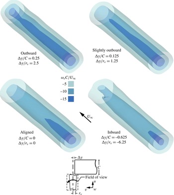
Figure 5 shows iso-surfaces of the streamwise vorticity
 $\unicode[STIX]{x1D714}_{x}C/U_{\infty }$
. The layout of these images and the designated values of
 $\unicode[STIX]{x0394}y/r_{v}$
correspond to the images of velocity deficit
 $1-u/U_{\infty }$
in figure 3. In accord with the surfaces of velocity deficit given in figure 3, the patterns of streamwise vorticity are sensitive to changes in the spanwise location of vortex impingement, again indicating upstream influence of the wing. The maximum value of streamwise vorticity is significantly altered, but unlike the surfaces of velocity deficit given in figure 3, the outer radii of the lowest level surfaces do not change significantly with either spanwise offset or streamwise position. However, as the location of vortex impingement moves inboard, the length of the highest level iso-surface of
 $\unicode[STIX]{x1D714}_{x}C/U_{\infty }=-15$
is attenuated, such that for the inboard interaction (
 $\unicode[STIX]{x0394}y/C=-0.625$
,
 $\unicode[STIX]{x0394}y/r_{v}=-6.25$
) it exists only in the region well upstream of the leading edge of the wing. In other words, the downstream boundary of the highest level iso-surface of
 $\unicode[STIX]{x1D714}_{x}C/U_{\infty }=-15$
retreats in the upstream direction for increased inboard displacement of vortex impingement; simultaneously, the diameter of this iso-surface decreases.
Iso-surfaces of streamwise vorticity
 $\unicode[STIX]{x1D714}_{x}C/U_{\infty }$
at four spanwise locations
 $\unicode[STIX]{x0394}y/r_{v}$
of vortex impingement. The surfaces extend over the streamwise distance from
 $0.125C$
to
 $1C$
upstream of the leading edge of the wing.

Further information related to the radial distribution of the streamwise vorticity can be determined by examining the distribution of circulation within the vortex. Although the total circulation of the vortex remains essentially constant over the range of streamwise locations in the field of view, varying by less than 3 %, the radial distribution of the circulation is, of course, not constant. Herein the core of the vortex is defined as having a radius
 $r^{\ast }$
that contains half of the total circulation of the vortex. Calculations show that the magnitude of
 $r^{\ast }$
increases in the streamwise direction by as much as 30 % as the leading edge of the wing is approached. Correspondingly, the magnitude of the peak vorticity along the centreline decreases by 29.7 %. Taken together with the decrease in the higher levels of axial vorticity indicated in the iso-surfaces of figure 5, this observation indicates that the average streamwise vorticity in the core of the vortex of radius
 $r^{\ast }$
decreases, while the average streamwise vorticity outside the core increases, as the vortex develops in the streamwise direction. Therefore, the aforementioned decrease of maximum axial (streamwise) vorticity is due to a redistribution of that vorticity out of the vortex core.
3.3 Azimuthal vorticity
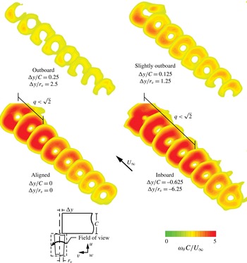
Figure 6 shows time-averaged slices of the azimuthal vorticity
 $\unicode[STIX]{x1D714}_{\unicode[STIX]{x1D703}}C/U_{\infty }$
, which is dominated by the derivative of streamwise velocity
 $u$
in the radial direction,
 $(\unicode[STIX]{x2202}u/\unicode[STIX]{x2202}r)C/U_{\infty }$
, relative to the other component of azimuthal vorticity, which is the derivative of the radial velocity in the streamwise direction,
 $(\unicode[STIX]{x2202}u_{r}/\unicode[STIX]{x2202}x)C/U_{\infty }$
. The highest levels of azimuthal vorticity take the form of well-defined rings which are centred on the axis of the vortex. As the spanwise location of vortex impingement moves from outboard to inboard, both the maximum value of azimuthal vorticity and its outer radius increase. An increase in the magnitude and outer radius of the ring of azimuthal vorticity can also be seen for decreasing values of
 $x^{\prime }/C$
, that is, for locations closer to the leading edge of the wing. These trends can be compared with the increase in velocity deficit indicated in figure 3. In essence, as
 $x^{\prime }/C$
decreases, the maximum values of both velocity deficit and azimuthal vorticity increase.
Slices of azimuthal vorticity
 $\unicode[STIX]{x1D714}_{\unicode[STIX]{x1D703}}C/U_{\infty }$
at four spanwise locations
 $\unicode[STIX]{x0394}y/r_{v}$
of vortex impingement. The slices extend over the streamwise distance from
 $0.125C$
to
 $1C$
upstream of the leading edge of the wing.

Garmann & Visbal (Reference Garmann and Visbal2015a
) show a helical instability around the perimeter of their incident vortex for streamwise locations where the swirl ratio
 $q<\sqrt{2}$
; this instability is evident in their instantaneous images. As indicated on the images of figure 6, the magnitude of the swirl ratio drops below this threshold value for both
 $\unicode[STIX]{x0394}y/r_{v}=0$
and
 $-$
6.25, at
 $x^{\prime }/C<$
0.5 and 0.75 respectively. In these regions, azimuthal vorticity has its largest magnitudes, corresponding to the same region as the helical instability observed by Garmann & Visbal (Reference Garmann and Visbal2015a
).
3.4 Cross-comparison of velocity defect and components of vorticity
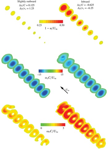
Figure 7 provides a direct comparison of time-averaged slices of the flow structure for two selected spanwise locations
 $\unicode[STIX]{x0394}y/r_{v}$
, of the incident vortex. Representative inboard (
 $\unicode[STIX]{x0394}y/r_{v}=-6.25$
) and outboard (
 $\unicode[STIX]{x0394}y/r_{v}=1.25$
) interactions are compared. For the inboard interaction, the following alterations are evident relative to the outboard interaction: enhancement of the magnitude and radial extent of the region of velocity defect
 $1-u/U_{\infty }$
; attenuation of the highest levels of streamwise vorticity
 $\unicode[STIX]{x1D714}_{x}C/U_{\infty }$
; and enhancement of the magnitude and radial extent of azimuthal vorticity
 $\unicode[STIX]{x1D714}_{\unicode[STIX]{x1D703}}C/U_{\infty }$
.
Sectional cuts of velocity defect, streamwise vorticity and azimuthal vorticity on streamwise-oriented planes at two different spanwise impingement locations
 $\unicode[STIX]{x0394}y/r_{v}$
. The sectional cuts extend over the streamwise distance from
 $0.125C$
to
 $1C$
upstream of the leading edge of the wing.

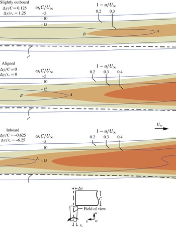
Longitudinal (axially oriented) cuts of streamwise vorticity
 $\unicode[STIX]{x1D714}_{x}C/U_{\infty }$
and streamwise velocity deficit
 $1-u/U_{\infty }$
contours along the axis of the vortex for three different spanwise locations
 $\unicode[STIX]{x0394}y/r_{v}$
of vortex impingement. Also shown is a dashed line that represents the vortex core radius
 $r^{\ast }$
.

Focusing on the comparison of the cross-sectional cuts of velocity defect and axial vorticity given in figure 7, as well as the iso-surfaces of these same parameters given in figures 3 and 5, it is evident that there is a close relationship between enhancement of the velocity defect and attenuation of the peak value of axial vorticity. A direct, quantitative comparison is given in figure 8, which shows superposition of (dark blue line) contours of constant axial vorticity and shaded regions of velocity defect for three impingement locations on a longitudinal cut through the vortex. In all cases, the tip
 $B$
of the moderate level of velocity defect
 $1-u/U_{\infty }=0.3$
extends well upstream through the centre of the vortex, and immediately downstream of this tip, the width of the region of vorticity defined by the lowest level contour
 $\unicode[STIX]{x1D714}_{x}C/U_{\infty }=-15$
rapidly decreases and goes to zero at the location
 $A$
. In other words, occurrence of a sufficiently large magnitude of the velocity defect promotes attenuation of high level vorticity along the vortex axis.
The axial vorticity was integrated over the entire cross-section of the vortex at successive streamwise locations along the axis of the vortex, and the magnitude of the circulation was found to be constant within 3 %. Herein, the core of the vortex is defined as the inner portion that contains one-half of the total circulation; it has a radius designated as
 $r^{\ast }$
. The dashed line on figure 8 defines the locus of
 $r^{\ast }$
, which increases over the streamwise extent of the vortex by approximately 33 %, 21 % and 10 % for the inboard, aligned, and slightly outboard cases respectively.
As indicated in the foregoing, with increasing streamwise distance along the vortex, the defect of axial velocity increases, the magnitude of the maximum value of the axial vorticity decreases, the circulation remains constant and the radius
 $r^{\ast }$
based on half-circulation increases. These changes in the vortex structure can be related to the adverse pressure gradient in the streamwise direction created by the downstream wing. In view of the fact that these parameters change rapidly over a small streamwise distance, a process of rapid distortion occurs, and inviscid effects dominate.
Iso-surfaces of upwash and downwash
 $w/U_{\infty }$
at four spanwise locations
 $\unicode[STIX]{x0394}y/r_{v}$
of vortex impingement. The surfaces extend over the streamwise distance from
 $0.125C$
to
 $1C$
upstream of the leading edge of the wing.

Cross-sectional cuts of upwash (positive) and downwash (negative)
 $w/U_{\infty }$
for four different spanwise locations
 $\unicode[STIX]{x0394}y/r_{v}$
of vortex impingement at
 $x^{\prime }/C=0.125$
. These plots also show (black) contour lines of wing-induced upwash
 $w/U_{\infty }$
due to the follower wing in absence of the incident vortex.

The inviscid theoretical model of Batchelor (Reference Batchelor1964) provides a guide for interpretation of the foregoing relationships. It focuses on the effect of streamwise pressure gradient, which can be related to the streamwise velocity variation in the inviscid vortex core via Bernoulli’s equation. If the pressure in the core increases in the axial direction, corresponding to an adverse pressure gradient, then the Batchelor (Reference Batchelor1964) theory indicates that the core diameter will increase provided that the circulation remains constant. Therefore, with this condition on circulation, an adverse pressure gradient is associated with both a decrease of axial velocity and a decrease in maximum vorticity, which is in line with the current experimental findings. Moreover, this relationship persists for varying values of offset of the incident vortex relative to the tip of the follower wing, that is, for different rates of deceleration of the vortex core, corresponding to different rates of increase of the velocity defect in the streamwise direction.
3.5 Upwash and downwash
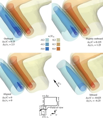
Iso-surfaces of (red-brown) upwash and (blue) downwash
 $w/U_{\infty }$
are given in figure 9. Consider first the case of the outboard interaction (
 $\unicode[STIX]{x0394}y/r_{v}=2.5$
). The (red-brown) upwash surfaces show little variation along the axis of the vortex, except in the region close to the leading edge of the wing, where the peak magnitude and spatial extent (radii) of the highest level surface is enhanced. Moreover, the (tan) surface representing the moderate levels of upwash extend further inboard as the leading edge of the wing is approached, and close to the leading edge these surfaces extend in the spanwise direction along the leading edge of the wing. These trends are due to the upwash component induced by the angle of attack of the wing, which exists in absence of the incident vortex, and has significantly large values close to the leading edge of the wing. That is, this wing-induced upwash enhances the magnitude and spatial extent of the upwash associated with the incident vortex. The foregoing trends for the outboard interaction (
 $\unicode[STIX]{x0394}y/r_{v}=2.5$
) persist at successive locations of the incident vortex further inboard, i.e. slightly outboard (
 $\unicode[STIX]{x0394}y/r_{v}=1.25$
), aligned (
 $\unicode[STIX]{x0394}y/r_{v}=0$
) and inboard (
 $\unicode[STIX]{x0394}y/r_{v}=-6.25$
) interactions. In fact, there is little difference in the shapes of the upwash surfaces between impingement locations.
Regarding the contours of (blue–green) downwash
 $w/U_{\infty }$
for the outboard interaction of figure 9, a clear decrease in the peak magnitude and spatial extent of the highest level surface of downwash occurs along the axis of the vortex as the leading edge of the follower wing is approached. This decrease with streamwise distance along the axis of the vortex is in accord with the increased magnitude of the upwash arising from the angle of attack of the wing. The attenuation of downwash magnitude with streamwise distance becomes increasingly prevalent at successive inboard locations corresponding to the slightly outboard, aligned and inboard interactions.
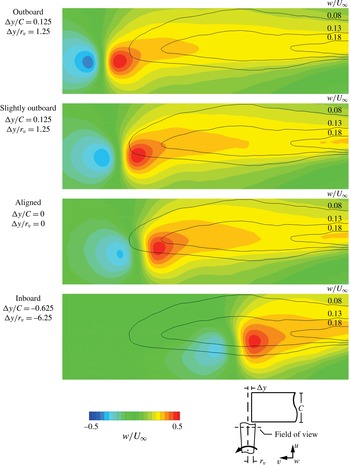
Figure 10 shows the superposition of: shaded contours of upwash and downwash of the incident vortex; and line contours of the wing-induced upwash in absence of the incident vortex. Both sets of contours are at a location close to the leading edge,
 $x^{\prime }/C$
= 0.125, for four different spanwise impingement locations. Comparison of the sets of contours at a given position of the incident vortex shows that the spanwise extension of upwash at locations inboard of the vortex axis is at least partially due to the self-induced upwash induced by the follower wing. Furthermore, low levels of the self-induced upwash of the wing are associated with a decrease of the maximum value of downwash of the vortex–wing interaction. The wing-induced upwash is additionally responsible for the increasing counter-clockwise rotation of the upwash and downwash contours around the vortex axis as the streamwise impingement location moves inboard. The highest levels of induced upwash are situated slightly vertically above the axis of the vortex, and when they combine with the incoming vortex, the results is rotated contours.
Plot of the magnitude of maximum upwash and downwash
 $w/U_{\infty }$
for different spanwise locations
 $\unicode[STIX]{x0394}y/r_{v}$
of impingement, as well as the no follower wing case. All cases are plotted as a function of streamwise location
 $x^{\prime }/C$
upstream of the leading edge of the wing. The shaded blue region represents the band of data corresponding to the no follower wing (FW) case.

Plot of the swirl ratio
 $q$
for different spanwise locations
 $\unicode[STIX]{x0394}y/r_{v}$
of impingement, as well as the no follower wing case. All cases are plotted as a function of streamwise location
 $x^{\prime }/C$
upstream of the leading edge of the wing.

Figure 11 shows the change in the maximum magnitude of both the upwash and downwash for all four values of vortex offset. For the case of the aligned (
 $\unicode[STIX]{x0394}y/r_{v}=0$
) and inboard (
 $\unicode[STIX]{x0394}y/r_{v}=-6.25$
) positions of the incident vortex, the overall decrease of the peak magnitude of downwash is approximately one-third of its initial value. In contrast, the peak upwash velocity shows only small changes in the streamwise direction for all values of spanwise offset of the vortex, except in the immediate vicinity of the leading edge, where there is clearly a rise of the order of one-eighth of the approach value.
3.6 Swirl ratio
Changes of the surfaces of velocity deficit
 $1-u/U_{\infty }$
, and
 $w/U_{\infty }$
described in the preceding figures 3 and 9 can be related to changes in the swirl ratio
 $q$
. Values of swirl ratio computed from the present experimental data are plotted in figure 12 as a function of distance
 $x^{\prime }/C$
upstream of the leading edge for the four different values of spanwise offset
 $\unicode[STIX]{x0394}y/r_{v}$
, i.e. the outboard, slightly outboard and aligned positions of the incident vortex, along with the no follower wing case. It is evident that the magnitude of swirl ratio continually decreases up to
 $x^{\prime }/C=0.25$
. At locations closer to the leading edge, the magnitude of the swirl ratio rises in the outboard and aligned cases. This rise is largest for the outboard position and smallest for the aligned position of the incident vortex. In accord with the computations of Garmann & Visbal (Reference Garmann and Visbal2015a
), this rise is due to acceleration of the core flow in that region. Moreover, the plot of the velocity deficit given in figure 4 shows a decrease of velocity deficit as the leading edge is approached for the outboard and slightly outboard cases and a fairly constant value for the aligned case, in contrast to the continued increase in velocity deficit for the inboard location.
Furthermore, for the aligned and inboard positions of the incident vortex, the decrease of swirl ratio as the leading edge is approached is relatively rapid, and small values of swirl ratio in the range of 1.0
 ${<}q<$
1.5 are eventually attained. A horizontal line on this plot defines the magnitude of
 $q=\sqrt{2}$
, which represents the critical value of swirl ratio for the
 $q$
-vortex according to Leibovich & Stewartson (Reference Leibovich and Stewartson1983), below which azimuthal instabilities are excited. For both the aligned and inboard positions of the incident vortex, the magnitude of the swirl ratio falls below this critical value for values of
 $x^{\prime }/C<0.5$
. From figure 12, these small values of swirl ratio correspond to large values of velocity deficit. This region where the values of
 $q<\sqrt{2}$
correspond to the region of large (dark red) azimuthal vorticity
 $\unicode[STIX]{x1D714}_{\unicode[STIX]{x1D703}}C/U_{\infty }$
is designated in figure 6. The occurrence of a helical instability embedded within the turbulent background of the incident vortex can produce enhanced values of time-averaged azimuthal vorticity. In the computations of Garmann & Visbal (Reference Garmann and Visbal2015a
) the nature of the incident vortex is shown as a laminar
 $q$
-vortex incident upon the leading edge, for which a helical instability is easily discernible near the leading edge.
3.7 Patterns of instantaneous and r.m.s. flow structure
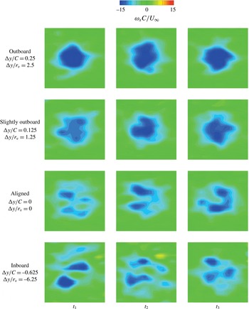
Figure 13 shows instantaneous images of streamwise vorticity
 $\unicode[STIX]{x1D714}_{x}C/U_{\infty }$
of the incident vortex at the location
 $x^{\prime }/C=0.125$
immediately upstream of the leading edge for four different impingement locations. At each spanwise location of vortex impingement, the three randomly selected images show variation of the pattern of vorticity. For the outboard case,
 $\unicode[STIX]{x0394}y/r_{v}=2.5$
, the vortex core is dominated by a single region of high streamwise vorticity for all images acquired at arbitrary instants
 $t_{1}$
,
 $t_{2}$
and
 $t_{3}$
. Near the outer edge of the vortex there are some irregularities, but the shape remains approximately circular. The slightly outboard case,
 $\unicode[STIX]{x0394}y/r_{v}=1.25$
, has regions of large streamwise vorticity that are more distorted, and the shape of the vortex is more irregular than at
 $\unicode[STIX]{x0394}y/r_{v}=2.5$
. The aligned case,
 $\unicode[STIX]{x0394}y/r_{v}=0$
, is even more irregular, and the core of the vortex is no longer identifiable. However, in all three instantaneous images the high level of streamwise vorticity is connected to a lower level of streamwise vorticity. For the inboard case,
 $\unicode[STIX]{x0394}y/r_{v}=-6.25$
, the regions of high streamwise vorticity are separated by regions of very low streamwise vorticity, such that they almost appear to be separate structures. This is most apparent in image
 $t_{1}$
, where the vortex has split into three separate regions of high streamwise vorticity.
Cross-sectional cuts of instantaneous streamwise vorticity
 $\unicode[STIX]{x1D714}_{x}C/U_{\infty }$
on streamwise-oriented planes at
 $x^{\prime }/C=0.125$
; four different spanwise locations
 $\unicode[STIX]{x0394}y/r_{v}$
of impingement are shown. The three different images in each row show different instantaneous images.

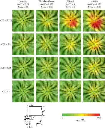
Figure 14 illustrates the effects of the impingement location
 $\unicode[STIX]{x0394}y/r_{v}$
and the upstream distance
 $x^{\prime }/C$
on the r.m.s. of the streamwise velocity
 $u_{rms}/U_{\infty }$
. In each image, the patterns of velocity vectors
 $V$
are superposed on the contours of
 $u_{rms}/U_{\infty }$
, thereby allowing identification of the centre of swirl. As the spanwise impingement location moves from outboard to inboard,
 $u_{rms}/U_{\infty }$
increases for all upstream positions. Furthermore, as
 $x^{\prime }/C$
decreases, the
 $u_{rms}/U_{\infty }$
values increase for the aligned and inboard impingement locations. The increase of values of
 $u_{rms}/U_{\infty }$
corresponds to the aforementioned increases in the velocity deficit
 $1-u/U_{\infty }$
. That is, comparing figures 3 and 14, it is evident that the patterns of largest
 $u_{rms}/U_{\infty }$
occur at the same streamwise location where the magnitude of the velocity deficit is largest, evident for the aligned and inboard interactions. Moreover, the patterns of largest
 $u_{rms}/U_{\infty }$
in figure 14 correspond to the lowest values of swirl ratio
 $q$
given in the plot of figure 12, in particular, regions where
 $q<\sqrt{2}$
for the aligned and inboard interactions.
Cross-sectional cuts of r.m.s. streamwise velocity
 $u_{rms}/U_{\infty }$
on streamwise-oriented planes; four different spanwise locations
 $\unicode[STIX]{x0394}y/r_{v}$
of impingement are shown.

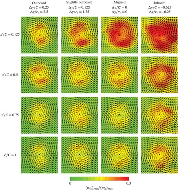
Figure 15 illustrates patterns of r.m.s. streamwise vorticity
 $(\unicode[STIX]{x1D714}_{x})_{rms}/(\unicode[STIX]{x1D714}_{x})_{max}$
which has been normalized by the local maximum value of the time-averaged streamwise vorticity
 $(\unicode[STIX]{x1D714}_{x})_{max}$
. The highest levels of
 $(\unicode[STIX]{x1D714}_{x})_{rms}/(\unicode[STIX]{x1D714}_{x})_{max}$
do not occur on the vortex axis; instead they are located in a ring surrounding the axis. Generally speaking, larger values of
 $(\unicode[STIX]{x1D714}_{x})_{rms}/(\unicode[STIX]{x1D714}_{x})_{max}$
tend to occur at smaller values of
 $x^{\prime }/C$
and at spanwise locations further inboard. At
 $x^{\prime }/C=0.125$
, the increase in magnitude and spatial extent of
 $(\unicode[STIX]{x1D714}_{x})_{rms}/(\unicode[STIX]{x1D714}_{x})_{max}$
with successive displacements of the impingement location of the incident vortex in the inboard direction correlates with increasing distortion of the instantaneous images given in figure 13. It also corresponds to the aforementioned increases of
 $u_{rms}/U_{\infty }$
and velocity deficit given respectively in figures 3 and 14, as well as associated decreases of swirl ratio given in figure 12.
Cross-sectional cuts of r.m.s. streamwise vorticity
 $(\unicode[STIX]{x1D714}_{x})_{rms}/(\unicode[STIX]{x1D714}_{x})_{max}$
on streamwise-oriented planes; four different spanwise locations
 $\unicode[STIX]{x0394}y/r_{v}$
of impingement are shown.

As shown in both figures 14 and 15, the r.m.s. contours depart from axisymmetry in this region of flow distortion, especially near the leading edge for the inboard and aligned impingement cases
 $\unicode[STIX]{x0394}y/r_{v}=0$
and
 $-$
6.25. For the type of encounter addressed herein, a nominally axisymmetric incident vortex approaches a planar leading edge, rather than an axisymmetric leading edge. This encounter likely induces non-axisymmetric distortions of the turbulent fluctuations and the mean flow in the vicinity of the leading edge.
4 Conclusions
The distortion of a trailing vortex from a leader wing incident upon the tip of a follower wing (flat plate) has been characterized using a stereoscopic technique of particle image velocimetry, thereby providing the flow structure of the incident vortex at locations well upstream of the follower wing for varying degrees of spanwise offset
 $\unicode[STIX]{x0394}y$
of the incident vortex relative to the tip of the wing designated as outboard (
 $\unicode[STIX]{x0394}y/r_{v}=2.5$
), slightly outboard (
 $\unicode[STIX]{x0394}y/r_{v}=1.25$
), aligned (
 $\unicode[STIX]{x0394}y/r_{v}=0$
) and inboard (
 $\unicode[STIX]{x0394}y/r_{v}=-6.25$
) of the tip, in which
 $r_{v}$
is the radius of the incident vortex.
The influence of the vortex–wing interaction is not simply confined to a localized region in the vicinity of the leading edge of the follower wing; rather, it can extend a distance upstream of at least one wing chord (approximately five vortex diameters). Moreover, significant upstream influence is evident when the tip of the vortex impinges well outboard of the tip of the follower wing.
The magnitude and radius of the region of streamwise velocity deficit
 $1-u/U_{\infty }$
of the incident vortex are significantly enhanced for the slightly outboard interaction and substantially altered for the aligned and inboard interactions, relative to the outboard interaction.
The value of the velocity deficit increases as the leading edge of the follower wing is approached, except in the domain close to the leading edge, where the velocity deficit either attains a plateau value or decreases. Correspondingly, the radius of the vortex increases while its circulation remains constant; this observation is associated with a potentially large decrease of streamwise vorticity in the vortex core and an increase outside the core. When rapid attenuation of high level vorticity occurs along the vortex axis, it is associated with existence of a sufficiently large magnitude of velocity defect.
The aforementioned enhancement of streamwise velocity deficit, attenuation of maximum streamwise vorticity and increase of vortex radius are linked to the adverse pressure gradient that exists in the region upstream of the wing. These observations are in accord with the inviscid theoretical model of Batchelor (Reference Batchelor1964), whereby the rapid distortion of the vortex structure approaching the wing is associated with dominance of inviscid mechanisms.
These alterations to the vortex structure correspond to a decrease in swirl ratio
 $q$
; when swirl ratio becomes sufficiently small, in particular in the region approaching the leading edge of the follower wing for the aligned and inboard interactions, a substantial increase in the time-mean azimuthal vorticity
 $\unicode[STIX]{x1D714}_{\unicode[STIX]{x1D703}}C/U_{\infty }$
arises along the outer periphery of the vortex. The largest enhancements of azimuthal vorticity occur when
 $q<\sqrt{2}$
, which is in accord with the theoretical prediction of Leibovich & Stewartson (Reference Leibovich and Stewartson1983) for small-wavelength instabilities about the vortex, and with the computations of Garmann & Visbal (Reference Garmann and Visbal2014a
, Reference Garmann and Visbal2015a
), which show an instantaneous helical instability about the exterior region of the vortex. On the other hand, for the cases of the outboard and slightly outboard interactions of the vortex with the tip of the wing, the swirl ratio
 $q$
does not reach values below the threshold value
 $q<\sqrt{2}$
, and enhancement of azimuthal vorticity does not occur along the entire streamwise extent of the incident vortex.
The attainment of lower values of swirl ratio
 $q$
also corresponds to the onset of relatively large values of r.m.s. fluctuations of streamwise vorticity
 $(\unicode[STIX]{x1D714}_{x})_{rms}/(\unicode[STIX]{x1D714}_{x})_{max}$
and axial velocity
 $u_{rms}/U_{\infty }$
on cross-sectional cuts of the incident vortex. The predominant magnitudes tend to be concentrated in a ring-like region surrounding the central portion of the incident vortex. Moreover, the largest r.m.s. magnitudes of these fluctuations are prevalent in the region immediately upstream of the leading edge of the follower wing, and for progressively further inboard locations of the incident vortex. The corresponding instantaneous structure of the streamwise vorticity
 $\unicode[STIX]{x1D714}_{x}C/U_{\infty }$
on a cross-sectional cut of the vortex, at a location upstream of the leading edge of the follower wing, shows progressively more severe degradation of the coherent structure of the vortex for decreasing values of swirl ratio, i.e. for further inboard locations of the incident vortex.
The foregoing changes of the incident vortex are associated with alterations of the upwash (positive vertical velocity
 $w/U_{\infty }$
) and downwash (negative
 $w/U_{\infty }$
). Downwash is attenuated as the leading edge of the follower wing is approached; corresponding values of upwash, however, do not change significantly, except for a mild enhancement in the immediate vicinity of the leading edge. Both of these effects are at least partially due to the self-induced upwash of the follower wing, which exists in absence of the incident vortex. This observation is deduced from comparison of upwash and downwash patterns for cases of an incident vortex and no incident vortex incident upon the follower wing.
Acknowledgement
This investigation was supported by AFOSR grant FA9550-14-1-0166, monitored by Dr D. Smith.