1. Introduction
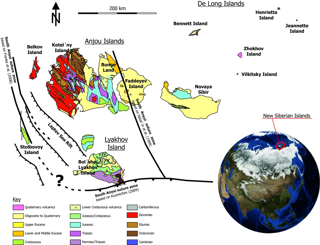
In the last decades, several plate tectonic models have been developed to explain the evolution of the Arctic region (e.g. Jones, Reference Jones1980; Rowley & Lottes, Reference Rowley and Lottes1988; Miller et al. Reference Miller, Toro, Gehrels, Amato, Prokopiev, Tuchkova, Akinin, Dumitru, Moore and Cecile2006; Shepard, Müller & Seton, Reference Shepard, Müller and Seton2013; Vernikovsky et al. Reference Vernikovsky, Dobretsov, Metelkin, Matushkin, Koulakov and Yu2013a ), but there are still many open questions. Little is known so far about the structural evolution of the New Siberian Islands, which are located in a key position on the east Russian Arctic shelf between the Laptev and the East Siberian seas (Fig. 1). This area is the western margin of the Alaska–Chukotka microplate (e.g. Miller et al. Reference Miller, Toro, Gehrels, Amato, Prokopiev, Tuchkova, Akinin, Dumitru, Moore and Cecile2006) and its structural evolution is important for understanding the Mesozoic–Cenozoic tectonic evolution of the Arctic region (Vernikovsky et al. Reference Vernikovsky, Metelkin, Tolmacheva, Malyshev, Petrov, Sobolev, Matushkin and Yu2013b ). Studies have focused on the tectonics of the Laptev Sea region (Fujita, Cambray & Velbel, Reference Fujita, Cambray and Velbel1990; Drachev et al. Reference Drachev, Savostin, Groshev and Bruni1998). Current models largely depend on offshore reflection seismics (Drachev et al. Reference Drachev, Savostin, Groshev and Bruni1998; Franke, Hinz & Oncken, Reference Franke, Hinz and Oncken2001; Franke & Hinz, Reference Franke and Hinz2005, Reference Franke and Hinz2009). The onshore structural evolution of the New Siberian Islands has only been analysed at selected locations (e.g. Kos’ko & Trufanov, Reference Kos’ko and Trufanov2002; Kuzmichev & Pease, Reference Kuzmichev and Pease2007; Kuzmichev, Reference Kuzmichev2009) and knowledge is limited. There are no recent datasets from the De Long Islands available. To close this gap, we present results of an onshore field-based structural analysis carried out during the Circum-Arctic Structural Events (CASE) 13 expedition in 2011, covering large parts of the New Siberian Islands including the De Long Islands.
Geological map of the study area. Map is based on VSEGEI, Position of the South Anyui suture zone is modified after Natal’in et al. (Reference Natal’in, Amato, Toro and Wright1999), Franke et al. (Reference Franke, Reichert, Damm and Piepjohn2008) and Kuzmichev (Reference Kuzmichev2009). Globe is taken from NASA World Wind.

The palaeo-shortening and palaeo-extension directions were derived from the trend of fold-axes and fault-slip data. Such datasets deliver important information for understanding the regional geodynamic evolution of the study area. In addition, understanding the orientation of faults and fractures is also important for hydrocarbon exploration (Gohram et al. Reference Gohram, Woodward, Callender and Greer1979; Narr Reference Narr1991; Hennings, Olson & Thompson, Reference Hennings, Olson and Thompson2000; Zahm & Hennings, Reference Zahm and Hennings2009) and drilling campaigns (Dusseault et al. Reference Dusseault, Maury, Sanfilippo and Santarelli2004). The Laptev and East Siberian seas are regarded as an important hydrocarbon province (e.g. Cramer & Franke, Reference Cramer and Franke2005; Khain, Polyakova & Filtova, Reference Khain, Polyakova and Filtova2009). Knowledge about the palaeo-shortening and palaeo-extension directions is crucial for exploration campaigns, because the orientation of natural fractures and faults in sedimentary basins are systematically related to the direction of the regional palaeostress field (Engelder & Geiser, Reference Engelder and Geiser1980). Nevertheless, perturbations can occur that modify the local stress field (Homberg et al. Reference Homberg, Hu, Angelier, Bergerat and Lacombe1997). Faults and fractures also have an influence on the subsurface fluid flow properties as they are discontinuities in the rock mass that can affect the vertical and lateral flow (Beaudoin et al. Reference Beaudoin, Bellahsen, Lacombe and Emmanuel2011, Reference Beaudoin, Lacombe, Bellahsen and Emmanuel2013).
The aims of this study were to: (1) present an analysis of the outcrop-scale brittle fabrics of the New Siberian Islands; (2) derive the directions of tectonic deformation of the eastern Laptev Sea and the western East Siberian Sea; and (3) connect the palaeo-shortening and palaeo-extension directions with the geodynamic evolution of the NE Russian Arctic region.
2. Geological setting and previous work
The New Siberian Islands are located between the Laptev Sea and the East Siberian Sea (Fig. 1). They can be divided into three groups: the Lyakhov Islands in the south; the Anjou Islands in the centre; and the De Long Islands in the northeast (Kos’ko & Trufanov, Reference Kos’ko and Trufanov2002). The Lyakhov and Anjou Islands represent a fold–thrust belt that evolved during Jurassic–Cretaceous time and is interpreted to be continuous from NW Alaska over northern Chukotka to the Laptev Sea area (Kos’ko & Trufanov, Reference Kos’ko and Trufanov2002; Bondarenko et al. Reference Bondarenko, Soloviev, Tuchkova, Garver and Podgornyi2003). The New Siberian Islands are regarded as a key area to understand the plate tectonic evolution of the Arctic region and the opening of the Amerasian Basin (Vernikovsky et al. Reference Vernikovsky, Dobretsov, Metelkin, Matushkin, Koulakov and Yu2013a , Reference Vernikovsky, Metelkin, Tolmacheva, Malyshev, Petrov, Sobolev, Matushkin and Yu b ). The offshore geology of the region has been comprehensively analysed over the last 15 years (Franke et al. Reference Franke, Hinz, Block, Drachev, Neben, Kos’ko, Reichert and Roeser1998, Reference Franke, Reichert, Damm and Piepjohn2008; Drachev et al. Reference Drachev, Savostin, Groshev and Bruni1998; Franke, Hinz & Oncken, Reference Franke, Hinz and Oncken2001; Franke, Hinz & Reichert, Reference Franke, Hinz and Reichert2004; Drachev, Reference Drachev, Spencer, Embry, Gautier, Stoupakova and Sorensen2011). These studies focused on the geodynamic evolution of the Late Cretaceous – Palaeogene Laptev Sea Rift, based on 2D-seismic reflection lines. The onshore geology of the New Siberian Islands was the subject of different studies dealing with the structural geology of Bol’shoi Lyakhov Island and the nature of the South Anyui suture zone (Kyz’michev et al. Reference Kyz’michev, Soloviev, Gonikberg, Shapiro and Zamzhitskii2006; Kuzmichev, Reference Kuzmichev2009). Additional work was carried out on the geochemistry of magmatic rocks of Belkov Island (Kuzmichev & Pease, Reference Kuzmichev and Pease2007) and on the structural style of parts of Kotel’ny Island and Novaya Sibir (Kos’ko et al. Reference Kos’ko, Lopatin and Ganelin1990; Kos’ko & Trufanov, Reference Kos’ko and Trufanov2002; Kos’ko & Korago, Reference Kos’ko and Korago2009). These studies were limited in their regional extent however, and there are no recent structural studies available for the De Long Islands. The most recent work on the New Siberian Islands and the De Long Islands has a focus on palaeomagnetics and biostratigraphy (Vernikovsky et al. Reference Vernikovsky, Dobretsov, Metelkin, Matushkin, Koulakov and Yu2013a , Reference Vernikovsky, Metelkin, Tolmacheva, Malyshev, Petrov, Sobolev, Matushkin and Yu b ).
Sedimentary rocks of Cambrian–Cenozoic age are exposed on the New Siberian Islands (Fig. 1). Igneous rocks are also present to a lesser extent. Ordovician rocks are represented by shallow-water carbonates in the northern part of Kotel’ny Island and by deepwater clastics on Bennett and Henrietta Islands. Belkov Island and the SW part of Kotel’ny Island are dominated by Devonian–Carboniferous shales (Fig. 1). Triassic–Cretaceous rocks are exposed in the central part of Kotel’ny Island. The Cretaceous rocks are widespread on the New Siberian Islands and vary from deepwater clastics (Bol’shoi Lyakhov Island, Stolbovoy Island) to sandstones (central Kotel’ny Island) to sands and soft coals (Novaya Sibir).
3. Methods
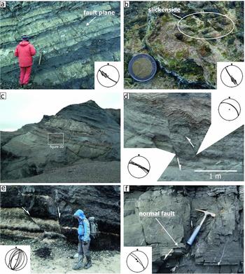
In more than 40 outcrops across the New Siberian Islands, the orientations of beds, faults and fractures as well as slickensides on these surfaces were measured (Fig. 2). Slickensides are important to derive the direction of movement along individual faults and are the basis for fault-slip analyses. We used the software FaultKin by R. Allmendinger to analyse the fault-slip data and to calculate P and T axes based on the approach of Marrett & Allmendinger (Reference Marrett and Allmendinger1990). We derived the directions of palaeo-shortening and palaeo-extension from the P and T axis orientations.
Outcrop photos and stereographic projections from the New Siberian Islands. (a) Strike-slip fault on Stolbovoy Island. The stereographic projection shows the orientation of the fault plane as a great circle and the slickenside striations as dots. (b) Serpentinite with slickenside on Bol’shoi Lyakhov Island. The great circle is the fault plane orientation and the dots indicate the plunge direction of the slickenside striations. (c) Fault-propagation fold on Novaya Sibir. (d) Detail of the fault-propagation fold. The structure was later cut by normal faults. The stereographic projection shows the fault planes as great circles. (e) Normal faults in Palaeogene sediments of northern Bunge Land. (f) Normal faults in Palaeozoic sedimentary rocks on Belkov Island. The stereographic projection shows the fault planes as great circles and the slickenside striations as dots.

3.a. Palaeostress field analysis
Palaeostress field analyses can provide valuable information which can lead to a better understanding of regional tectonic processes and the deformation history of sedimentary basins (Delvaux et al. Reference Delvaux, Moeys, Stapel, Petit, Levi, Miroshnichenko, Ruzhich and San’kov1997; Saintot & Angelier, Reference Saintot and Angelier2002). Such palaeostress reconstructions reflect the past stresses in the crust for a certain period of deformation, averaged over the duration of a tectonic event (Lacombe, Reference Lacombe2012).
Different techniques were developed in the last decades to analyse the orientation of tectonic deformation phases and the related palaeostress field evolution. Hancock & Kadhi (Reference Hancock and Kadhi1978) used conjugate joint sets to derive the horizontal stress trajectories. They showed that conjugate fracture systems that enclose a small dihedral angle probably developed as a consequence of failure in the shear extension fracture transition. This allows the orientation of the three principle stresses, which are referred to as σ 1, σ 2 and σ 3, to be derived. In such a system σ 1 bisects the smallest dihedral angle and σ 2 is parallel to the intersection of the conjugate fractures. From the orientation of the conjugate fractures, the direction of the three principle stresses can be constrained. Another joint based approach was presented by Engelder & Geiser (Reference Engelder and Geiser1980) to derive the palaeostress field of the Appalachian Plateau. Parallel to the joint set approach, techniques of fault-slip analysis were developed which are now well established and proven to deliver robust results.
3.a.1. Fault-slip analysis
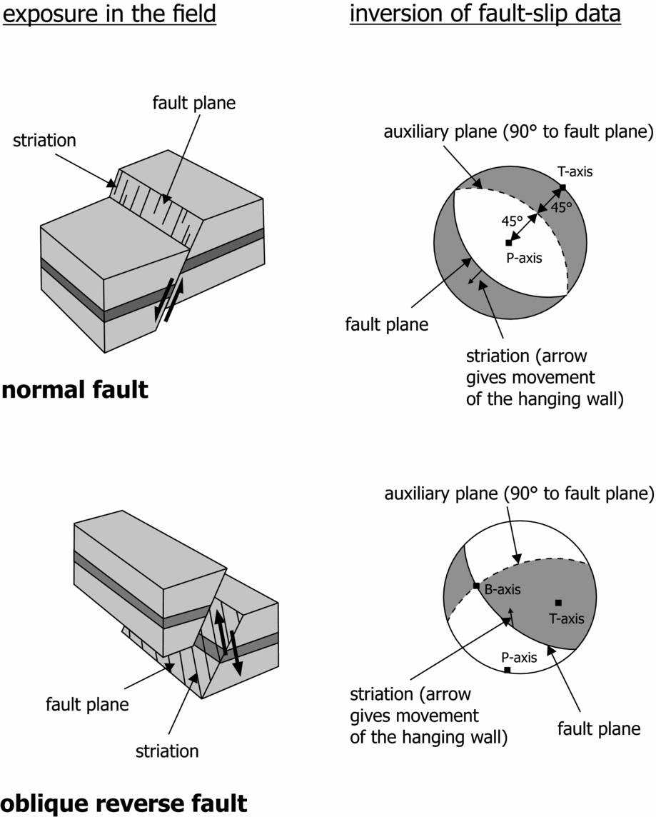
Pioneer work on fault-slip analysis was carried out by Angelier & Mechler (Reference Angelier and Mechler1977). They introduced the so-called right dihedra method that allows the orientation of the principle stresses to be derived graphically from fault-slip data. The key concept of the right dihedra method is the construction of an auxiliary plane that cuts through the fault plane at an angle of 90° and trends perpendicular to the slip direction. Both planes (fault plane and auxiliary plane) define four quadrants, two compressional and two extensional (Angelier & Mechler, Reference Angelier and Mechler1977). The maximum principle stress lies within the pressure quadrant, whereas the minimum principle stress is placed in the tensional quadrant. From the quadrants, the positions of the so-called P- and T-axes can be derived. The P-axis (pressure) and the T-axis (tension), also named ‘shortening’ and ‘extension’ axes, respectively, lie at 45° to the fault plane and the auxiliary plane (Fig. 3). They represent the principle axes of the incremental strain tensor of the related fault (Marrett & Allmendinger, Reference Marrett and Allmendinger1990). The intersection of the fault plane and the auxiliary plane is referred to as the B-axis. Over the years further techniques were developed for fault-slip analysis, in particular for processing heterogeneous fault-slip datasets (Yamaji, Reference Yamaji2000; Zalohar & Vrabec, Reference Zalohar and Vrabec2007; Sato, Reference Sato2012).
Concept of fault-slip analysis. The fault plane and the auxiliary plane define four quadrants (two compressional and two extensional). The maximum principle stress lies within the pressure quadrant, whereas the minimum principle stress is placed in the tensional quadrant. From the quadrants, the position of the so-called P- and T-axes can be derived. Modified after Berghemer (Reference Berghemer1990).

3.a.2. Fracture pattern analysis
The analysis of fracture pattern associated with folding can provide important information about the evolution of fold structures. Many previous studies have focused on the evolution of fold-related fractures (Harris et al, Reference Harris, Taylor and Walper1960; Lisle, Reference Lisle1994; Fischer & Wilkerson, Reference Fischer and Wilkerson2000; Bellahsen, Fiore & Pollard, Reference Bellahsen, Fiore and Pollard2006; Amrouch et al. Reference Amrouch, Lacombe, Bellahsen, Daniel and Callot2010). Early models such as that of Stearns & Friedman (Reference Stearns, Friedman and King1972) describe two conjugate fracture sets referred to as pattern 1 and pattern 2. Both sets have the common feature that σ 1 and σ 3 are parallel to the bedding plane (Stearns & Friedman, Reference Stearns, Friedman and King1972). The bisecting vector of the acute angle in the conjugate fracture set defines the orientation of σ 1 (Hancock, Reference Hancock1985). In the model of Stearns & Friedman (Reference Stearns, Friedman and King1972), the orientation of the conjugate fracture sets varies with the bed trend of the anticline. For the pattern 1, the minimum bisection angle is perpendicular to the outline of the fold. More recent studies developed new fold–fracture models. Bergbauer & Pollard (Reference Bergbauer and Pollard2004) showed that fractures formed during folding can be strongly influenced by pre-folding joint sets. Their model described two almost orthogonal pre-folding joint sets. During folding, new joints form parallel to the pre-existing joints on the fold limbs. The hinge area is also characterized by the development of new fractures. None of the syn-folding fractures run parallel or orthogonal to the hinge line (Bergbauer & Pollard, Reference Bergbauer and Pollard2004). Mynatt, Solomon & Pollard (Reference Mynatt, Solomon and Pollard2009) presented a conceptual model for fracture evolution during folding based on the Raplee Monocline: two sets of pre-folding fractures form an orthogonal pattern, which is overprinted by fracture reactivation and the formation of new fractures during folding. A comparable observation was made by Lacombe, Bellahsen & Mouthereau (Reference Lacombe, Bellahsen and Mouthereau2011) in the Zagros Fold Belt, where pre-/early folding fractures and some syn-folding fractures developed. This shows that fracture development during folding varies over time. Further controlling factors for fracture pattern evolution are the material properties (Mynatt, Solomon & Pollard, Reference Mynatt, Solomon and Pollard2009) and the distance to the orogenic front (Beaudoin et al. Reference Beaudoin, Lepretre, Bellahsen, Lacombe, Amrouch, Callot, Emmanuel and Daniel2012).
4. Field data
4.a. Belkov Island
Belkov Island is located in the western part of the study area (Fig. 1). The analysed section extends along the SE coastline. Outcrop conditions are good and allow the assessment of sedimentological and structural data. The exposures are dominated by very thin-bedded siltstones and shales, with minor intercalations of thin- to medium-bedded, fine-grained sandstones. The siltstones and shales are horizontally laminated, whereas the intercalated sandstone beds often show ripple cross-stratification with ripple form sets (8 cm from crest to crest) and small-scale flame structures (up to 0.6 cm high). The depositional ages of the rocks range from Late Devonian to Early Carboniferous (Kuzmichev & Pease, Reference Kuzmichev and Pease2007). They are unconformably overlain by unconsolidated Palaeogene sediments. Metre-scale open folds are developed in the Palaeozoic rocks, generally with NW–SE-trending fold axes. Only a minor fold has an east–west-trending axis, reconstructed on the basis of intersection lineations. The shales and siltstones show a pronounced slaty cleavage with cleavage planes steeply dipping towards the NE and SW. The succession is characterized by steeply dipping, NW—SE-trending normal faults (Fig. 2f) and east–west-trending sinistral strike-slip faults. In the northern part of the analysed section, syn-sedimentary normal faults and small (decimetre scale) recumbent folds are developed within the siltstones.
4.b. Kotel’ny Island
The western and central part of Kotel’ny Island is characterized by large anticlines with NW–SE-trending fold axes. Three different areas of Kotel’ny Island were analysed, the first located at the centre of the island. Due to the low topography, the exposure conditions are very limited and only isolated outcrops occur. Locally sandstone and pebbly sandstones crop out, which are characterized by thin- to medium-bedded sandstones and pebbly sandstones with components of up to 10 cm in diameter. Some beds have a lenticular shape and show a horizontal stratification or a cross-stratification. The sandstone succession is characterized by coal intercalations. The rocks have an Early Cretaceous age (Aptian–Albian) and belong to the so-called Balyktakh Formation (Kuzmichev, Aleksandrova & Herman, Reference Kuzmichev, Aleksandrova and Herman2009). Within the sandstone packages, fracture sets are developed with fractures that trend east–west and NNW–SSE.
The second area is located in the NW of Kotel’ny Island, where Devonian–Triassic rocks are exposed. These coastal outcrops are dominated by dark shales which show north–south- and NE–SW-trending fractures. There is evidence for NNE–SSW-trending sinistral strike-slip faults.
The third study area is also at the coast, south of the second location. Ordovician–Devonian sedimentary rocks are exposed at this part of Kotel’ny Island, ranging from very thin-bedded shales to very thick-bedded carbonates. Fracture sets dominate, which mainly consist of NNE–SSW- and NW–SE-trending joints. In addition, NW–SE-oriented sinistral strike-slip faults occur.
4.c. Bunge Land
The analysed section is located at the NE coast and exposes unconsolidated Palaeogene sands and amber-bearing soft coal/lignite. Several planar normal faults are developed that dip to the NW and SE. They have offsets in the range of 0.2–1 m and form conjugate or synthetic patterns (Figs 2e, 4a). In addition, north–south-trending oblique strike-slip faults and roughly east–west-trending normal faults are developed.
(a) Stereographic projections of the outcrop data. (b) Map of the tectonic deformation. The red arrows indicate the palaeo-shortening direction and the green arrows show the direction of palaeo-extension. The shortening direction delineates the trend of the South Anyui suture. The grey fault plane solutions are calculated on the basis of the outcrop data; the blue solutions are derived from earthquakes.

4.d. Stolbovoy Island
The analysed fabrics on Stolbovoy Island are developed in Lower Cretaceous thin- to very thick-bedded siltstones and fine-grained sandstones, which are interpreted as turbidite sequences (Figs 2a, 4a). Outcrop conditions along the sea cliff are good and allow structural data to be assessed. Large normal faults and strike-slip faults are exposed, which trend north–south and NW–SE, respectively. The north–south-trending strike-slip faults show dextral movements and slickenside, and the NW–SE-trending strike-slip faults indicate sinistral movements.
4.e. Bol’shoi Lyakhov Island
A wide range of magmatic and metamorphic rocks are exposed on the SE coast of Bol’shoi Lyakhov Island; the outcrops are small and restricted to river valleys and the coastline. Exposed pillow basalts with mid-ocean-ridge basalt (MORB) geochemistry (Kuzmichev, Reference Kuzmichev2009) and related serpentinites (Fig. 2b) are interpreted as remnants of the South Anyui Ocean (Kyz’michev et al. Reference Kyz’michev, Soloviev, Gonikberg, Shapiro and Zamzhitskii2006). NW–SE-trending dextral strike-slip faults have developed in the serpentinites. Thrust fault have developed at two locations in the basaltic rocks. The rocks are also characterized by a set of mostly north–south-trending fractures that can be observed in different outcrops. In addition, WNW–ESE-, ENE–WSW- and NE–SW-trending fractures have developed.
4.f. Novaya Sibir
The analysed section consists of slightly consolidated to unconsolidated Cretaceous (Turonian, age from Herman & Spicer, Reference Herman and Spicer2010) fine-grained sands and lignite. Individual lignite seams reach a thickness of 10 m. The basal part of the section shows a small fault-propagation fold, with a concentric hanging wall anticline (Fig. 2c, d). The dataset derived from the Turonian sediments on Novaya Sibir also shows WNW–ESE-trending reverse faults that are offset by WNW–ESE-trending normal faults (Fig. 2d). Some of the reverse faults could also have been reactivated as normal faults.
4.g. Zhokhov Island
Zhokhov Island is part of the De Long Island group and it is characterized by Plio-Pleistocene basaltic rocks (Fig. 4a; Bogdanovskii et al. Reference Bogdanovskii, Mineev, Assonov, Silantyev, Karpenko, Shukolyukov and Savostin1992; Silantyev et al. Reference Silantyev, Bogdanovskii, Fedorov, Karpenko and Kostitsyn2004). Observation of outcrops was limited due to widespread snow and ice coverage; however, a set of small WNW–ESE- to east–west–trending normal faults were exposed in one outcrop. The normal faults enclosed a vertical acute angle.
4.h. Henrietta Island
Ordovician sandstones and volcanic rocks are exposed on Henrietta Island. Observation of outcrops was limited due to widespread snow and ice coverage, but the presence of NE–SW-trending sinistral strike-slip faults was noted; minor NNE–SSW-trending dextral strike-slip faults also occur (Fig. 4a).
4.i. Bennett Island
Bennett Island is the largest and westernmost island of the De Long group. The analysed section extends along the SE coast and includes Cambrian–Ordovician sedimentary rocks which are overlain by Cretaceous basalt. The sedimentary rocks are sheet-like thin- to medium-bedded mudstones, siltstones and sandstones. The beds are massive or horizontally laminated. The sandstones and siltstones show frequent climbing ripple cross-stratification and pronounced convolute bedding. The bases of the beds are mostly planar, in some cases also erosive. The beds dip towards ENE with low angles between 4° and 12°. Several vertical NW–SE- and WSW–ENE-trending fracture sets are exposed. The intersection line of the fracture sets in vertical.
5. Orientations of the tectonic deformation phases
The most reliable indicators for the tectonic deformation in this study are the trend of anticlinal axes and fault-slip data. From the fault-slip data inversion, the palaeo-shortening and the palaeo-extension directions can be directly derived. Fault-slip data inversion was only possible for faults that showed distinct striations. A map was created based on the dataset, in which the orientation of the major horizontal palaeo-shortening directions are indicated by red arrows and the major horizontal palaeo-extensional direction are given by green arrows (Fig. 4b). Horizontal shortening was the dominant tectonic deformation. The NE–SW-directed palaeo-shortening is the most distinct direction. It can be observed on Stolbovoy, Belkov, Kotel’ny and Henrietta Islands. On Belkov and Kotel’ny Islands in particular, this shortening direction can be derived from the trend of fold axes; the NW–SE-oriented sinistral strike-slip faults on Kotel’ny Island might also belong to this phase. On Stolbovoy and Kotel’ny Islands there is also evidence for a NNW–SSE-directed horizontal shortening. Data from central Kotel’ny Island also give evidence for a WNW–ESE-directed horizontal shortening. On Bol’shoi Lyakhov Island a NNE–SSW-directed horizontal shortening can be observed and there is also evidence for a WNW–ESE-oriented shortening (Fig. 4b).
Data from Belkov Island and northern Bunge Land indicate a NE–SW- to NNE–SSW- directed horizontal palaeo-extension. This extension affected Carboniferous rocks on Belkov Island (Fig. 2f) and Palaeocene sediments on Bunge Land (Fig. 2e). However, it must be kept in mind that the normal faults on Belkov Island trend parallel to the fold axes and could therefore also represent crestal collapse related to folding.
The De Long Islands show a similar pattern to the Anjou and Lyakhov Islands. Strike-slip fault data from Henrietta Island yield evidence of a NE–SW-palaeo-contraction. In Neogene volcanic rocks on Zhokov Island (Fig. 4b), small WNW–ESE-trending conjugate normal faults have developed (Fig. 4a) that fit into the extensional regime derived from fault-slip data on Belkov Island and Bunge Land (Fig. 4b).
5.a. Limitations and uncertainties
Deriving palaeostress data from fault-slip data has certain limitations, but its reliability is beyond doubt (Lacombe, Reference Lacombe2012). In this study the greatest uncertainties arise from the limited data set. The outcrops are small and isolated. In some areas, only a few fault planes with striations are exposed (e.g. on Belkov and Kotel’ny Islands), whereas on Stolbovoy Island for example many faults planes with striations have developed. Nevertheless, the prominent NE–SW-palaeo-shortening can also be confirmed on the basis of fold axes, indicating that the fault-slip data are reliable. Datasets on the extensional structures are also limited, but the derived palaeo-extension direction fits to the trend of normal faults observed on seismic lines (e.g. Drachev et al. Reference Drachev, Savostin, Groshev and Bruni1998; Franke, Hinz & Oncken, Reference Franke, Hinz and Oncken2001; Franke & Hinz, Reference Franke and Hinz2005, Reference Franke and Hinz2009).
5.b. Timing of deformation
To analyse the temporal evolution of the tectonic deformation, the different shortening and extension directions were tied to the stratigraphy of the region. The temporal resolution of the deformation phases remains limited however, due to the fact that many of the analysed outcrops are small and isolated. As a consequence of the restricted temporal resolution, only a preliminary deformation pattern can be derived. Horizontal palaeo-shortening affected all rocks older than Palaeocene throughout the New Siberian Islands. There is no evidence for contractional deformation in Palaeogene–Neogene rocks. The exposure on Novaya Sibir (Fig. 2c, d) indicates that WNW–ESE-trending reverse faults and the fault-related folds were offset by WNW–ESE-trending normal faults. The extensional phase is therefore the youngest deformation phase affecting the area. Normal faults with the same trend as on Novaya Sibir were observed in late Neogene volcanic rocks on Zhokov Island, confirming that the extension is the youngest tectonic phase.
5.c. Fracture analysis
The fracture pattern analysis is difficult because of the limited exposure; fractures can only be approximately separated into pre-folding and syn-folding. The fractures in western Kotel’ny form an orthogonal pattern (Fig. 4a). The observed fracture pattern is most likely related to a pre-folding phase, comparable to the models developed by Bergbauer & Pollard (Reference Bergbauer and Pollard2004) and Mynatt, Solomon & Pollard (Reference Mynatt, Solomon and Pollard2009). In NW Kotel’ny fracture sets have developed on an anticlinal limb and enclose a low angle; there are small offsets visible along the individual fractures. Both fracture sets offset each other, which might imply that they were contemporaneously active. The model of Mynatt, Solomon & Pollard (Reference Mynatt, Solomon and Pollard2009) provides a potential explanation for this fracture pattern. A pre-folding fracture set is reactivated during folding and a second new fracture set forms.
6. Discussion
Previous studies identified different tectonic phases on the New Siberian Islands. Kos’ko & Korago (Reference Kos’ko and Korago2009) described at least three deformation phases, ranging from a Caledonian shortening of the early Palaeozoic sedimentary rocks, followed by an Early Cretaceous tectonic phase (based on the observation of an unconformity below the Aptian–Albian deposits) and a phase of Cenozoic faulting. Kyz’michev et al. (Reference Kyz’michev, Soloviev, Gonikberg, Shapiro and Zamzhitskii2006) also observed a Jurassic–Cretaceous deformation phase based on syn-collisional sediments and attributed it to the closure of the Anyui Ocean.
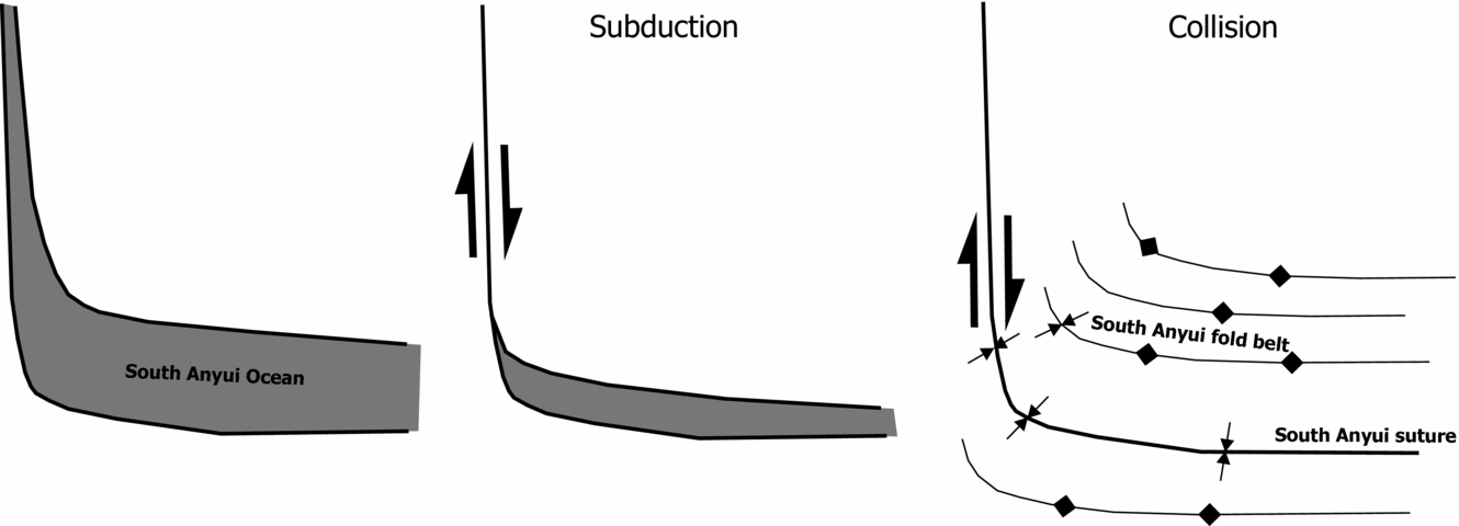
Similarly, our structural dataset gives evidence for a polyphase tectonic deformation of the Laptev and East Siberian Sea area. We identified three palaeo-shortening directions (NE–SW, WNW–ESE and NNW–SSE to NNE–SSW) and one set of palaeo-extensional directions (NE–SW to NNE–SSW). The NE–SE-directed shortening is the most prominent tectonic deformation. It can be observed on many of the New Siberian Islands and clearly dominates the study area (Fig. 4b). Evidence for this shortening direction is given by the trend of fold axes on Belkov and Kotel’ny Island and can be also derived on the basis of the fault-slip data from Stolbovoy, Kotel’ny and Henrietta Islands (Fig. 4b). This shortening direction most likely reflects the fold belt formation (collisional stage) after the southwards-directed subduction of the Anyui Ocean (Fig. 5). On Bol’shoi Lyakhov Island, the shortening rotates into a more NNE–SSW direction. This fits with the local east–west trend of the South Anyui suture described by Kuzmichev (Reference Kuzmichev2009). Reverse faults and thrusts on Bol’shoi Lyakhov Island give also evidence for a WNW–ESE shortening (Fig. 4b).
Schematic model for the closure of the South Anyui Ocean.

Although the tectonic fabrics are very distinct it is difficult to temporally separate the palaeo-shortening directions; it is therefore difficult to decide whether they represent clear individual tectonic phases, or simply belong to one tectonic event that caused different shortening directions. Verzhbitsky & Khudoley (Reference Verzhbitsky and Khudoley2010) conclude that the NE–SW shortening is the oldest phase followed by the WNW–ESE contraction, which they attribute to post-collisional movement. Our data show that the pattern of tectonic deformation directions is quite homogeneous over the New Siberian Islands, with common horizontal palaeo-shortening directions. This supports the findings of Vernikovsky et al. (Reference Vernikovsky, Dobretsov, Metelkin, Matushkin, Koulakov and Yu2013a ) who concluded, from the match of the palaeomagnetic directions between the territories of the Anjou and De Long archipelagos, a tectonic unity had been present at least since Early Ordovician time.
The South Anyui suture is an important structural element in the Russian Arctic. It forms the southern and western boundary of the Alaska–Chukotka microplate (Miller & Verzhbitsky, Reference Miller and Verzhbitsky2009), but the exact westwards extent of the South Anyui suture zone is still under debate (Sokolov et al. Reference Sokolov, Bondarenko, Layer and Kravchenko-Berezhnoy2009; Kuzmichev, Reference Kuzmichev2009). Different scenarios have been discussed. Fujita et al. (Reference Fujita, Stone, Layer, Parfenov and Kos’min1997) assume that the suture has a strong bend and shows a north–south trend between Bol’shoi Lyakhov and Faddeyev Islands. In contrast, Natal’in et al. (Reference Natal’in, Amato, Toro and Wright1999) propose that the suture splits into a WNW–ESE–trending branch that is exposed on Bol’shoi Lyakhov Island and a NNW–SSE–trending branch crossing Faddeyev Island. Rowley & Lottes (Reference Rowley and Lottes1988) assume that the South Anyui suture zone runs east of the New Siberian Islands. Based on seismic reflection lines, Franke et al. (Reference Franke, Reichert, Damm and Piepjohn2008) suggested a bend in the South Anyui suture between Stolbovoy and Bol’shoi Lyakhov Islands. In their model, the suture trends WNW–ESE in the area of Bol’shoi Lyakhov Island and shifts into a more NNW–SSE–directed orientation between Stolbovoy and Kotel’ny Islands (Fig. 1). This model is supported by field data. Most outcrops on Belkov and Kotel’ny indicate a NE–SW-directed palaeo-shortening (Fig. 4b). On Bol’shoi Lyakhov Island there is evidence for a NNE–SSW-oriented palaeo-shortening, which is roughly perpendicular to the trend of the South Anyui suture. This would fit with a bending of the suture from an east–west trend in the south of the archipelago into a NNW–SSE trend in the west. Palaeogeographic reconstructions of the evolution of the Arctic region imply that the western part of the South Anyui suture is a large strike-slip zone (Fig. 5; Shepard, Müller & Seton, Reference Shepard, Müller and Seton2013). This is also consistent with the shortening direction in the western part of the study area.
What is the consequence for our still insufficient knowledge of the kinematics and history of the pre-Tertiary opening of the Arctic Ocean Basin? Lawver & Scotese (Reference Lawver, Scotese, Grantz, Johnson and Sweeney1990) discuss a variety of models for the origin of the Amerasia Basin. Among the numerous models there is a popular model that involves the opening of the Amerasia Basin by in situ seafloor spreading and anticlockwise rotation of the Arctic Alaska–Chukchi–Ancestral Plate away from Arctic Canada about a pivot point situated in northern Yukon. It is still unclear if only portions of or the entire Amerasia Basin opened along such a shear zone, but our data indicate that such a mechanism would at least be consistent with the geology of the New Siberian Islands. The main shear zone would have run from the Amerasia side of the Lomonosov Ridge onto the Laptev Sea shelf.
The WNW–ESE-oriented shortening direction is much more difficult to explain. As mentioned above, Verzhbitsky & Khudoley (Reference Verzhbitsky and Khudoley2010) attribute the WNW–ESE contraction to post-collisional movements. Another possibility is wrench-dominated transpressional deformation as per the model of Tikoff & Teyssier (Reference Tikoff and Teyssier1994), but this would require a more NNE–SSW trend of the South Anyui suture west of Kotel’ny Island. A comparable contraction with a WNW vergence was observed in the Verkhoyanks fold–thrust belt between 150 and 120 Ma (Konstantinovsky, Reference Konstantinovsky2007). This would fit with the contraction direction observed on the New Siberian Islands, and the WNW–ESE stress direction could be a far-field effect of deformation in the Verkhoyanks fold–thrust belt.
The extension (NE–SW to NNE–SSW, green arrows in Fig. 4b) observed on Belkov Island, Kotel’ny Island, Bunge Land, Novaya Sibir and Zhokov Island is clearly the youngest phase and most likely a consequence of rifting in the Laptev Sea. The extension fits the orientation of major normal faults of the Laptev Rift (Drachev et al. Reference Drachev, Savostin, Groshev and Bruni1998; Franke, Hinz & Oncken, Reference Franke, Hinz and Oncken2001; Franke, Hinz & Reichert, Reference Franke, Hinz and Reichert2004; Franke & Hinz, Reference Franke and Hinz2005). The extensional direction derived from the fault-slip inversion can be also confirmed on the basis of recent earthquake focal mechanisms shown in Franke, Krüger & Klinge (Reference Franke, Krüger and Klinge2000) and Gaina, Roest & Müller (Reference Gaina, Roest and Müller2002) (Fig. 4b). Some of these focal mechanisms provide evidence of locally pronounced strike-slip movements.
7. Conclusions
The New Siberian Islands are affected by different tectonic phases, three palaeo-shortening directions (NE–SW, WNW–ESE and NNW–SSE to NNE–SSW) and one palaeo-extension direction (NE–SW to NNE–SSW). All observed phases are Mesozoic–Cenozoic in age. The horizontal shortening is related to the closure of the South Anyui Ocean. The NE–SW-oriented palaeo-shortening is the most prominent tectonic direction in the study area and reflects the fold–thrust belt formation during the collision. The WNW–ESE and the NNE–SSW- to NNW–SSE-oriented palaeo-shortening directions are likely also a consequence of the formation of the South Anyui fold belt. The NNE–SSW- to NNW–SSE-directed contraction could have been the result of the bend in the suture zone and the related along-strike changes in shortening direction. The last tectonic phase was extensional. Normal faults, developed in relatively unconsolidated (Cenozoic) sediments, indicate that the extension was younger than the shortening phases and was probably related to the evolution of the Laptev Sea Rift. This extensional phase extended towards the northeast and is also visible in brittle fabrics developed in young volcanic rocks on Zhokov Island.
Acknowledgements
P. Sobolev and T. Tolmasheva (VSEGEI, St Petersburg) are thanked for logistics and scientific support. The BGR is gratefully acknowledged for financial support. The BMBF/German Federal Ministry of Education and Research (Internationales Büro des BMBF) is gratefully acknowledged for financial supporting C. Brandes (RUS 11/A09). Finally, we thank O. Lacombe and H. Lorenz for constructive reviews.