


Introduction
As part of the WISSARD (Whillans Ice Stream Subglacial Access Research Drilling) project, the ANDRILL Science Management Office at the University of Nebraska-Lincoln was subcontracted in 2011 to design, build and operate a traverse-transported hot-water drill capable of penetrating cold glacial ice to >800 m depth in order to access the subglacial environment beneath Whillans Ice Stream (WIS), West Antarctica. The drill was built to generate as much as 2 7 0 L min 1 of clean (having acceptably low levels of biological and chemical contaminants) hot water (90°C). At the heart of the drill are six Alkota 12257K pressure washers for heating the drill water, each of which is capable of delivering 45 L min−1 of water whose temperature has been raised by 52°C. (See Reference RackRack and others, 2014, for an overview of the WISSARD drill and for discussion of its thermal power output.) Because water from two (sometimes three) of the six pressure washers was needed to melt snow, the drill typically was operated using a hot-water discharge rate of 135–180 L min−1 , which represents the flow from three or four Alkota units; 2 7 0 L min−1 is an upper limit for output assuming all six Alkota units are used to send water to the drill from an already existing reservoir of water pre-heated to 35°C.
The snowmelter’s main tasks are to supply seed water to get the water-heating components of the drill primed for start-up, then to fill a storage tank with a water reserve large enough to melt through the initial firn layer – at the Subglacial Lake Whillans (SLW) site the firn gave way to solid ice at ∼40m depth. Drill water released into the porous firn is essentially non-recoverable; once the drill has penetrated solid ice, the water is confined to the drillhole and is then recoverable by means of a submersible pump. Once this phase of drilling is reached, the snowmelter’s purpose is to provide make-up water, which replenishes the ∼10% volumetric loss in the hole resulting from the phase transition of the ice from solid to liquid. Due to the mobile nature of the drill and the time constraints of the project, a Rodriguez well was deemed impractical to meet these needs (Reference Schmitt and RodriguezSchmitt and Rodriguez, 1963; Reference Lunardini and RandLunardini and Rand, 1995). Since the drill was powered by a 225 kW diesel generator fitted with heat exchangers to capture waste heat from the engine cooling system as well as the engine exhaust system, it was decided that the snowmelt system should use this waste heat as part of the melting process. The melt system would need to adhere to the clean-access constraints of the overall drill (it would also supply most of the water for day-to-day camp operations including drinking water), so a method of heat exchange with the generators would need to be devised that would avoid chemical contamination of the water supply from the glycol. The design of the system would need to incorporate flexibility in directing water quickly to various parts of the drill system, be movable and be able to take in large amounts of snow from a skid loader or other machinery. Figure 1 shows the melt tank’s schematic relationship to the rest of the WISSARD drill components.
Flow schematic for the WISSARD hot-water drill showing the placement of the snowmelt system relative to other components of the drill system. Wavy lines indicate connections made via surface hoses.

Design/Build Phase
Design ideas for the snowmelting system evolved from a similar system used by the drill for the ARA (Askaryan Radio Array) project at South Pole Station, Antarctica (Reference BensonBenson and others, 2014). Notable changes made include the addition of heat exchange plates to utilize waste heat from the camp generators, increased pump capacity, and stainless-steel plumbing to minimize water contamination. The build phase for the WISSARD drill began in July 2011 (see Reference RackRack and others, 2014, for details relating to project history); work on the snowmelting system began in December 2011. In order to save time during the build process, parts were sourced from commercial vendors whenever possible. This included the tank, heat exchange plates, and plumbing. In-house modifications, while necessary, were kept to a minimum. A custom hopper was designed and built of 19 mm plywood to increase the amount of snow that could be loaded into the system. Figures 2 and 3 show the melt tank hopper and heat exchange plates, respectively. All low-pressure hose connections were made using stainless-steel cam-and-groove-style fittings; high-pressure hose connections were made using stainless-steel JIC (Joint Industry Council) flare-style fittings.
The finished snowmelt tank showing hopper with exterior bracing. On the right are the pump and expansion tank for the glycol subsystem.

The melt tank interior during build showing heat exchange plates and submersible transfer pump lying in the bottom of the tank. The manifold system can be seen in profile atop the tank.

Tank
The tank used was a 1900 L dairy mixer modified by welding stainless Unistrut® inside and out to hold various structural additions. Foremost among these was a hopper to accommodate snow loading via a skid-steer (Caterpillar 297) loader equipped with a bucket. As such, the hopper needed to be of sturdy construction and well supported. The outer Unistrut® pieces were crucial in providing mounting points for the bracing (also an off-the-shelf Unistrut® product) for the hopper. This was custom-built out of 19 mm plywood that was lined on the inside with 6 mm polyurethane sheeting. A system to add heat to the tank without using seed water was devised using semi-customized heat exchange plates that would circulate glycol through the melt tank from the cooling system of the online generator. These plates were made by Omega Thermo Products in Wisconsin using the dimensions specific to our tank. The tank’s add-on plumbing was designed to allow recirculation of high-pressure hot water from the drill heating units back to the melt tank. Like the rest of the drill system, the melt system uses stainless steel in all aspects of water handling. The snow hopper was lined with polyurethane to prevent contamination from the plywood that comprises it; the glycol heat exchange plates were made of heavy-gauge stainless steel to withstand stress from shipping and snow loading; and the plumbing was made of stainless-steel fittings and food-grade hose. Possible sources of contamination were still present in the quality of snow used (snow was mined from a location less likely to have been contaminated by camp activity – in this case, outside of the downwind footprint of the camp and upwind of the main generators), in the bucket used on the loader, and in the proximity of camp staff aiding in snow loading. We assumed that possible contaminants from these sources would be minimal and would be easily handled by the filtration/sterilization subsystem of the drill (Reference PriscuPriscu and others, 2013).
Plumbing/liquid handling
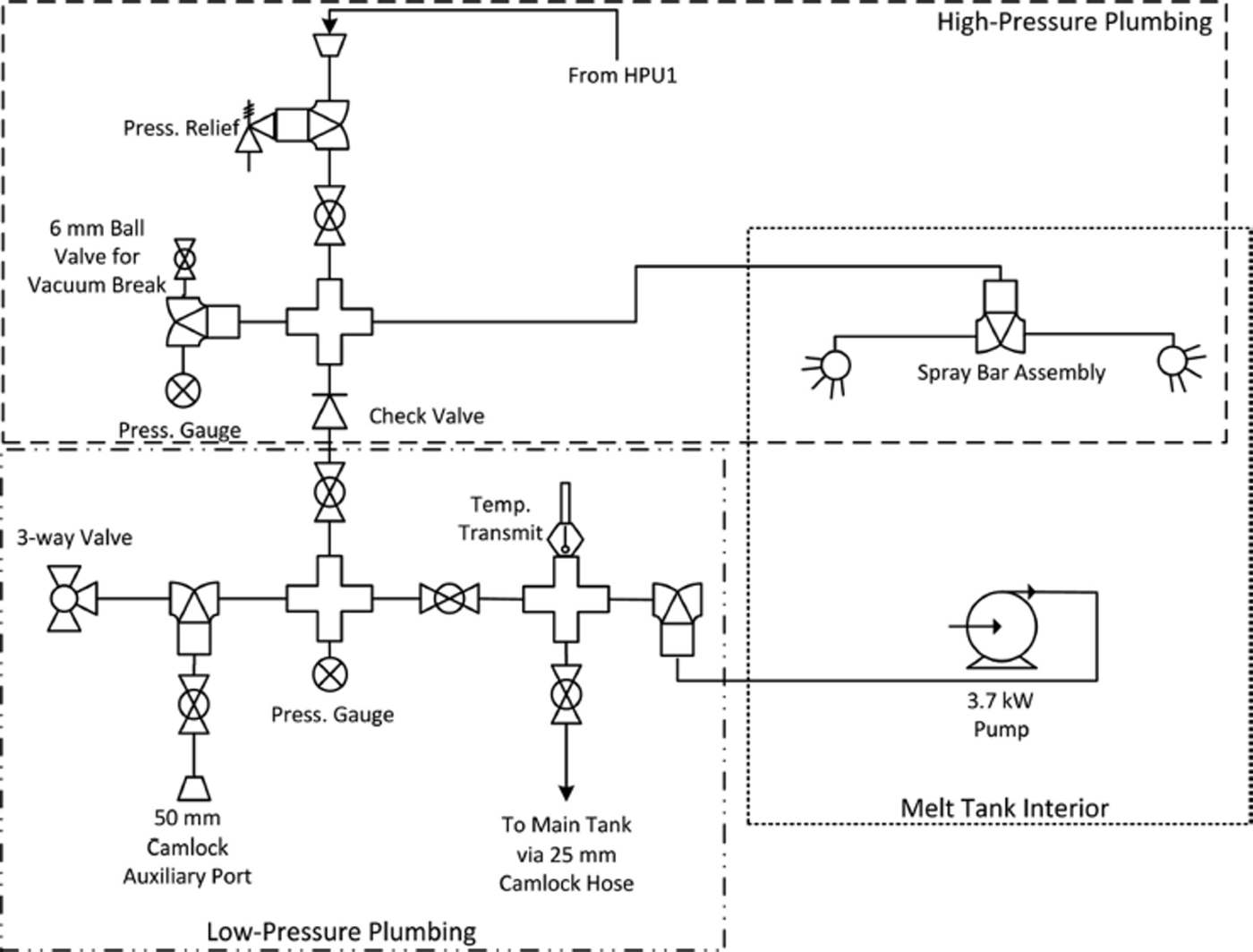
Figure 4 shows the plumbing diagram for the melt tank; the plumbing was designed to maximize options for moving water in different directions. This assembly was mounted on the top of the tank and covered by an insulated housing that is part of the hopper assembly (see Fig. 5 for a front view of the manifolding). A low-pressure (rated at 10 bar) submanifold had valving that allowed water to be sent from the melt tank to the main (14 000 L) water tank (and on to the drill via the filtration unit input), or redirected back to the melt tank for use in melting snow. There was also an auxiliary valved output for local water extraction or for unforeseen system modifications. A high-pressure (rated at 207 bar) submanifold allowed receipt of hot water from the main drill for use in high-speed snowmelting via a spray bar hanging inside the tank. The spray bar was equipped with a 220Lmin 1 full-cone spray nozzle at either end. A strategically placed high-pressure check valve allowed the sprayer assembly to take either low-pressure water from the melt tank itself or high-pressure water from the drill water heaters. Lying in the bottom of the tank was a Grundfos 75S30-5 centrifugal pump with a 3.7 kW, 460V three-phase motor. This pump was capable of transferring >230 L min −1 from the melt tank and was connected to the low-pressure submanifold via a food-grade hose. Four glycol heat exchange plates were mounted inside the tank; each had a capacity of 53 L. Food-grade glycol (mixed 1 :1 with water) was fed into and out of the plates at either end via 20 mm welded fittings. A centrifugal pump (Grundfos CRI 15-2) mounted on the front of the tank skids supplied glycol at ∼250 L min−1 via a four-way manifold. After passing through the plates, glycol was recombined at another four-way manifold at the opposite end of the tank, from where it flowed back to the generators. An expansion tank, mounted beside the pump, allowed for expansion of the glycol with increased temperature. Three glycol reserve tanks were mounted on the back of the melt tank. Portable vinyl containment berms were used where possible when manipulating glycol line fittings and containers in order to minimize environmental releases.
Water-plumbing diagram for the melt tank.
Operator’s view of the tank manifold system shown in the melt tank water-plumbing diagram.

Electrical/sensing
The system was equipped with various gauges (local readout) and sensors (input to overall drill system data stream): Each manifold had a pressure and temperature gauge; the low-pressure submanifold had a temperature sensor tied into the main drill control system for remote monitoring of tank water temperature. A drop-in temperature probe was used for local monitoring of tank water temperature. The glycol subsystem had gauges for glycol pressure and temperature, as well as temperature and pressure sensors connected to the main control system. The water and glycol pumps were controlled using a local switch on a power distribution station near the melt tank. The main drill operator was able to monitor the status of these switches but did not have remote control over them.
Field Operations
Once the main generator was operational, the melter’s glycol subsystem was connected to the generator coolant inlet/outlet ports to enable the flow of glycol through the heat exchanger plates in the melter. With hot (60–70°C) glycol flowing through the plates delivering ∼50 kW of heat to the tank, a tankful of snow could be melted in 2–3 hours. This provided priming water to start the main drill heating units (Alkota 12257K pressure washers) to feed hot water back to the melter via the spray bar. At this point, melting could begin in earnest as the spray bar was capable of melting a steady input of snow from the loader. With two Alkota units (90 L min−1) supplying hot water back to the melter, the output pump would outpace the tank fill rate; with three Alkotas (135 L min−1), the tank filled with water faster than the pump could extract it and send it to the main tank and the drill. Since the melt tank pump could move 230 L min−1 of water, this indicates a snowmelt rate of >230–135 = 95 L min−1, or >32 L min−1 of snowmelt per Alkota unit. (We did not have the capability to vary the pump speed, otherwise we could have gained a much better estimation of the amount of meltwater produced.) This estimate is bolstered by the fact that we could balance drill output with meltwater production alone when drilling with a flow of ∼90 L min−1 (this is a lower drill output than usual – two Alkotas’ worth of flow instead of three – which required the drill speed to be reduced from 1 m min-1 to 0.5-0.7 m min−1). As a result of this, if the main holding tank is depleted of water and/or the downhole pump becomes inoperable, the drill will not necessarily have to be stopped to wait for a water reserve to be re-established. (Although possible, we do not recommend trying to drill an entire hole of this depth using snowmelt alone. The preceding discussion was merely meant to illustrate the usefulness of this snowmelter in bridging potential water supply deficiencies arising during normal drilling.) See Appendix B for a more in-depth discussion of drilling using only water from the snowmelter.
Operation in the field was optimized by the presence of one or two people with shovels to aid in settling the snow into the melter’s reservoir of hot water. The water jets from the spray bar generally would melt large air pockets into the snow load, and constant closing of these pockets by the shovelers greatly expedited snowmelting. A small loader (in this case a Caterpillar 297; Fig. 6) equipped with a bucket was essential for maintaining a constant, high-volume input of snow to the melter. (The drill team had at least four qualified forklift drivers, and the supporting traverse crews were all qualified heavy equipment operators.) The loader’s ability to provide a thick layer of snow on top of the water in the tank also minimized water loss due to evaporation. The tank minders also controlled the operation of the transfer pump, which was not automated with sensors/actuators to maintain a constant water level in the tank. Spillage was problematic in that it destabilized the snow on which the tank was resting, and a human presence helped minimize this risk. Likewise, operators were needed occasionally to reconfigure the manifold valving depending on the drill’s requirements.
Caterpillar 297 skid steer loader feeding snow into the melter.

Identified Areas for Improvement
The most obvious improvement to this system would be the addition of a level sensor/transfer pump switch feedback loop to automate the maintenance of constant water level in the tank. This would reduce the number of people needed to staff the melter by at least one (conceivably, a single person driving the loader would be enough to maintain a steady output of meltwater). The melter’s output would be increased with the use of a larger pump in the tank, allowing more hot water from the drill water heaters to be directed to the melt tank without overwhelming it; this would also allow drilling to continue at closer-to-normal speeds in the event that the melt tank alone had to supply water to the drill.
A further operational improvement would be to design a melt system whose top sits near the snow surface. This would allow snow to be mounded around and pushed into the melter by a blade-equipped tractor rather than dumped from a skid-steer bucket. During the 2013/14 Antarctic season, this concept was successfully demonstrated (with a smaller hot-water drill) to increase the rate at which snow could be fed into the melter while reducing the necessary manual labor. A Case quad-track with a large blade was able to push a large mound of snow into/around a snowmelt tank every few hours or so, after which one person with a shovel was sufficient to continue pushing snow into the melter from the surrounding snow mound, letting gravity pull snow into the tank. The current design of the WISSARD melt tank is not suitable to this arrangement, as access to valving would be hindered by snow build-up around the tank.
Black plastic sheeting on the inside of the hopper would aid in snowmelting via solar gain. We used white sheeting due to time constraints (black sheeting had a longer lead time for ordering). A tank with pre-existing refrigeration coils could allow glycol to be circulated through tank walls, reducing the risk of water contamination with glycol. Our tank has some of this plumbing but we did not have time to test its integrity and it only covers part of the tank’s length. The fact that these coils are in the walls of the tank would also likely reduce the efficiency of heat transfer to the snow/water in the tank. A larger hopper and/or a hopper equipped with a macerator would eliminate the need for people to constantly pack the snow load with shovels. However, this would complicate the overall design of the melt system and significantly increase required power and materials costs.
We hope to better quantify the energy input and water output characteristics in future field seasons by more thoroughly monitoring the flow rates and temperatures of the glycol and water. A non-functioning flowmeter on the glycol inlet and lack of flow instrumentation on the melt tank’s water output line made it difficult to track the values necessary for a more quantitative assessment of this system’s capabilities.
Acknowledgements
We gained much of our experience in hot-water drilling from the IceCube project’s Enhanced Hot Water Drill (EHWD) from about 2004 to 2010. The experience gained during this time informed everything from our facility with plumbing to a semi-intuitive grasp of heat and fluid flow. We also acknowledge the ARA (Askaryan Radio Array) project’s drill team for the initial design idea for our melt system. The Engineering and Science Research Support Facility at the University of Nebraska–Lincoln was instrumental in the design and build of the melt tank’s undercarriage, as well as some of the welding required in retrofitting the tank. We also acknowledge the following businesses for their advice and service in the building of this system: Ullmer’s Dairy Products (Pulaski, WI), Lincoln Fabrication and Welding (Lincoln, NE), Kelly Supply Co. (Lincoln, NE) and Omega Thermo Products, Inc. (Stratford, WI).
Appendix A: Thermal Input For Snow Melting
Due to schedule and budget constraints during the build phase of the drill, we lacked instrumentation that could measure all temperatures and flows associated with snowmelter operation. As such, the thermal input power had to be estimated for this paper.
For the snowmelter, there are two primary heat inputs: the generator waste heat coming via the glycol loop, and the hot water coming from the drill’s main water heaters. During normal operation the WISSARD drill loaded the generator at an estimated 60 kW, plus another estimated 20 kW from the electrical needs of the camp. Based on IceCube experience with these generators (Reference BensonBenson and others, 2014), we assume a recovered waste-heat to electrical-load ratio of 1.2; this implies a waste heat recovery of 96 kW. Furthermore, the amount of this heat that is recoverable by our system will be some fraction of this value. We estimate that the generator heat exchangers have an efficiency of 70%, and the heat exchange plates inside the snowmelter have the same. Assuming 100 kW of waste heat coming from the generator, this amounts to ∼50 kW of heat input to the melter via the glycol plates.
With the generator and two drill water heaters supplying heat to the snowmelter, and a thermal power value per heater of 175 kW (see appendix of Reference RackRack and others, 2014), we have a thermal input power for the snowmelter of

Appendix B: Hot-Water Drilling Using Only Snowmelter Water
There were a few occasions in the field when the main water tank became depleted of water or (more rarely) we had to stop the downhole (return) water pump for an extended length of time. In these instances we discovered that the snowmelt tank was able to meet all of the water needs of the drill by itself. As mentioned in the Field Operations section, the operational state of the drill system had to be changed to allow this; during normal operations we would use three or four Alkota units to feed water to the drill hose (135–180 L min−1), and two Alkota units to feed water to the melt tank (90 L min−1). However, to drill on snowmelt alone required feeding the drill hose with two Alkota units while using three to feed water to the melt tank (90 L min−1 to the drill hose and 135 L min−1 to the melt tank). As mentioned in the Field Operations section, each Alkota realized an estimated net gain of meltwater exceeding 3 2 L min−1, which translates to > 9 6 L min−1 for three Alkotas – more than enough to provide water to the two Alkota units dedicated to drilling. In addition, the glycol plates generate an estimated 5 – 6 L min-1 of meltwater with the electrical load we typically had on our generator.
As a result of the reduced flow to the drill head, the drill speed would need to be reduced in order to have a uniform borehole width (although it would also be possible to have a narrower hole during this time that could later be reamed at a lower speed when the drill head is on its way back up the hole). The reduced drill speed would obviously increase hole production time, all other things being equal; for an 800 m hole, a scenario of doubled drill time (0.5 m m in 1 up and down for the entire hole instead of 1.0 m min-1) would have meant ∼54 hours to complete the hole instead of 27 hours and would have required significantly more labor to keep melting snow for this entire time. However, this drill time scenario was still within the contingency limits established by the science team when they drew up the timeline for science instrument access to the borehole.



