





Nomenclature
Abbreviations
- AM
-
additive manufacturing
- PBF
-
powder bed fusion
- L-PBF
-
laser powder bed fusion
- SLM
-
selective laser melting
- EBM
-
electron beam melting
- DED
-
directed-energy deposition
- DMD
-
Direct metal deposition
- WAAM
-
wire arc additive manufacturing
- GMAW
-
gas metal arc welding
- GTAW
-
gas tungsten arc welding
- PAW
-
plasma arc welding
- FDM
-
fused deposition modeling
- SLA
-
stereolithography
- CAD
-
computer-aided design
- STL
-
standard tessellation language
- HIP
-
hot isostatic pressing
- AFM
-
Abrasive flow machining
- MAF
-
magnetic abrasive finishing
- EDM
-
Electrical discharge machining
- NDT
-
non-destructive testing
- NDE
-
non-destructive evaluation
- CT
-
Computed tomography
- SEM
-
scanning electron microscopy
- AE
-
acoustic emission
- HAZ
-
heat-affected zone
- LRE
-
liquid rocket engine
- LCF
-
low cycle fatigue
- LoF
-
lack of fusion
- CMC
-
ceramic matrix composite
- CFRP
-
carbon fibre reinforced polymer
- DfAM
-
design for additive manufacturing
- ML
-
machine learning
- AI
-
artificial intelligence
- CNC
-
computer numerical control
1.0 Objectives
The application of metal additive manufacturing (AM) to rocket propulsion has attracted growing attention over the past decade, yet existing reviews address AM either broadly across industries or across aerospace as a whole without sufficient focus on propulsion-specific constraints. DebRoy et al. provide a comprehensive treatment of AM metals from a materials science perspective but without propulsion-specific application depth, while Blakey-Milner et al. discuss about AM across the aerospace sector, treating propulsion as one subsection among many [Reference DebRoy, Wei, Zuback, Mukherjee, Elmer, Milewski, Beese, Wilson-Heid, De and Zhang1, Reference Blakey-Milner, Gradl, Snedden, Brooks, Pitot, Lopez, Leary, Berto and du Plessis2]. Neither consolidates process selection, material compatibility, defect behaviour and post-processing within the operational context of rocket propulsion, where constraints such as cryogenic propellant compatibility, regenerative cooling geometries, hydrogen embrittlement resistance and extreme thermomechanical cycling impose requirements qualitatively different from broader aerospace manufacturing.
This review addresses that gap by providing a propulsion-focused assessment that connects AM process capabilities directly to component-level requirements. It examines powder bed fusion (PBF) and directed energy deposition (DED) in the context of combustion chambers, injectors, nozzles and turbopump assemblies, evaluating material-process compatibility and the defect mechanisms most relevant to propulsion hardware. The available evidence is synthesised to compare additive and conventional manufacturing in terms of performance, cost and reliability, and a process selection framework is proposed that maps component requirements to AM methods based on resolution, build scale and material constraints. In doing so, this paper aims to serve as a consolidated reference for engineers and researchers working at the intersection of AM and rocket propulsion development, and to identify where further research and standardisation are most critically needed.
2.0 Search strategy
This review was conducted as a review of the state-of-the-art in rocket propulsion AM. Literature was primarily sourced using Google Scholar, the NASA Technical Reports Server (NTRS) and ScienceDirect. The search focused on peer-reviewed journal articles, conference proceedings from the American Institute of Aeronautics and Astronautics (AIAA) and the American Society of Mechanical Engineers (ASME), and technical reports from 2010 to 2025. Key search terms included `metal additive manufacturing’, `selective laser melting’, and `directed energy deposition’. Papers were selected based on their relevance to fusion-based metal AM processes and their application to high-stress propulsion components.
3.0 Introduction
AM has transformed component fabrication in the aerospace sector by enabling the production of complex geometries through a layer-by-layer material deposition process. This approach allows for the creation of parts that are difficult or impossible to manufacture using traditional subtractive methods. An example of AM’s impact is Rocket Lab’s Rutherford engine, the world’s first 3D-printed electric-pump-fed orbital rocket engine, in which the combustion chamber, injectors, pumps and main propellant valves are made using laser powder bed fusion (L-PBF), with all primary components producible within 24 hours [3].
Among the various AM technologies, PBF, particularly selective laser melting (SLM), is the most widely used in aerospace applications. This method uses a high-powered laser or electron beam to selectively fuse metal powders, producing intricate, high-performance components with excellent dimensional accuracy and strength [Reference Radhika, Shanmugam, Ramoni and Gnanavel4]. Another promising technique is DED, which builds parts by feeding metal powder or wire through a nozzle while simultaneously melting it with a focused energy source. Due to its scalable nature, DED is also employed in the repair and refurbishment of large, high-value components, further extending their lifecycle.
This review focuses on the application of AM techniques, specifically PBF and DED, in the production of propulsion-specific components such as combustion chambers, injectors, nozzles and turbopumps. These components are subject to extreme thermal and mechanical stresses, presenting unique challenges and opportunities for additive approaches. The paper aims to examine current practices, technological capabilities, post-processing requirements and areas for future development in the context of rocket engine manufacturing.
4.0 Materials for AM of rocket components
Material selection plays a vital role in the performance, reliability and manufacturability of rocket propulsion components fabricated using AM. Unlike traditional manufacturing, AM imposes constraints such as thermal gradients, residual stresses and build-direction anisotropy, which require careful consideration of how a material behaves during and after the build.
Rocket engines, particularly liquid rocket engines (LREs), operate in extreme conditions including high temperature, pressure, rapid thermal cycling and exposure to cryogenic and reactive fuels like liquid hydrogen. As a result, materials must demonstrate high thermal conductivity, strength-to-weight ratio, resistance to low cycle fatigue (LCF), resistance to hydrogen embrittlement and good compatibility with the selected AM process.
This section explains key material requirements, common alloys and composites, compatibility with AM processes and real-world use in current rocket systems.
4.1 Material requirements for propulsion applications
Each engine component is exposed to unique thermal and mechanical loads. This means that material requirements depend heavily on the intended application. Table 1 describes some of the material requirements for rocket engine components.
Key material requirements for rocket engine components

Table 1. Long description
A table with two columns and six rows. The first column is labeled ‘Requirement’ and the second column is labeled ‘Description’. Row 1: Requirement, Thermal conductivity; Description, Important for cooling channels and combustion chambers. Row 2: Requirement, Yield strength; Description, Needed to resist pressure loads in injectors and chamber walls. Row 3: Requirement, Low-cycle fatigue (LCF); Description, Occurs due to repeated start-stop cycles during engine firings. Row 4: Requirement, Elongation and ductility; Description, Helps prevent brittle failure under sudden thermal or mechanical shocks. Row 5: Requirement, Hydrogen embrittlement resistance; Description, Required for components exposed to cryogenic hydrogen.
For example, the RS-25 engine uses materials like Inconel and HR-1 that meet strict thresholds for strength, fatigue life and chemical resistance in hydrogen environments [Reference Dean5, Reference Katsarelis, Chen, Gradl, Protz, Jones, Ellis and Evans6].
Since no material perfectly meets all these requirements, trade-offs are often made based on the component’s function and operating conditions. For example, combustion chambers may prioritise thermal fatigue resistance and high temperature strength, while injector components may require higher toughness and corrosion resistance.
Material development for rocket propulsion AM often involves engineering alloys and superalloys specifically optimised to balance these properties, sometimes incorporating composites or coatings, such as carbon fibre reinforced polymer (CFRP), to enhance performance further.
4.2 Common alloys and composites
AM in the aerospace industry heavily relies on metallic alloys and high-performing composites. These materials provide superior thermal resistance and conductivity, which are essential for most applications in the field. Common materials include copper-based, nickel-based and iron-based superalloys, each optimised for specific properties like thermal conductivity, fatigue resistance or compatibility with cryogenic fuels.
Nickel-based alloys such as Inconel 625 and Inconel 718 are widely used in rocket engine components. They are selected for their excellent thermal resistance, corrosion resistanceand weldability [Reference Gradl and Msfc7]. In contrast, NASA’s HR-1, a nickel-iron super-alloy, was developed to address issues like hydrogen embrittlement and fatigue resistance in LRE components.
For components requiring excellent heat dissipation, such as combustion chamber liners or thrust chambers, copper-based alloys are commonly used. Examples include GRCop-42, GRCop-84 and NARloy-Z. GRCop-42 and GRCop-84 contain small amounts of chromium and niobium, with total solute contents of 6 at.% and 12 at.%, respectively (Cr: 4 at.% and 8 at.%, Nb: 2 at.% and 4 at.%), while NARloy-Z includes silver and zirconium in much smaller proportions (Ag:
 $\approx$
1.8 at.%, Zr:
 $\approx$
0.35 at.%), with copper as the balance in all three alloys [Reference Gradl, Protz, Cooper, Ellis, Evans and Garcia8–Reference Bhat, Greene and Singh10].
Titanium alloys are often chosen for structural components or mounting hardware due to their high strength-to-weight ratio and corrosion resistance. These alloys are among the most extensively researched materials in aerospace applications [Reference Frazier11]. Composites materials, especially fibre-reinforced polymers (FRPs), are used in non-combustion applications where additional strengthening is required whilst minimising weight. Composites such as CFRP, in which carbon fibres are embedded in an epoxy or thermoplastic resin matrix, are mainly used for housing or outer casings of parts since they are lightweight and have good fatigue performance. The limitations of using CFRP are that it cannot be used in hot gas flow paths or combustion zones due to thermal degradation. There are other composites such as ceramic matrix composites (CMC) that are specially made to be used in the hot sections of advanced reusable rocket engines because of their thermal insulation properties [Reference Herbell and Eckel12].
When deciding the most suitable material, certain trade-offs must be made, as there is no material that fits all cases. For example, copper alloys are thermally conductive but structurally weak, while nickel alloys are structurally strong but very poor conductors of heat. Hence, components are often designed with material constraints in mind.
In powder-based AM processes like SLM, EBM or DED, the choice of feedstock material plays an important role in determining the final part quality. These methods typically utilise pre-alloyed metal powders or wire feedstock with controlled particle size distributions and chemical compositions to ensure consistent melting, bonding and mechanical performance. It is important to note that binder-based techniques, such as binder jetting, are not commonly employed for propulsion-critical components due to their lower extensive post-processing requirements. As such, this review focuses on fusion-based metal AM methods that do not incorporate binders in their fabrication process.
4.3 Microstructural and mechanical challenges in AM materials
AM parts face unique microstructural and mechanical challenges (see Figure 1) that directly affect the performance in a high-stress environment like rocket engine components. One of the most common challenges for fusion-based AM techniques is the formation of residual stresses, which arise from steep thermal gradients and constrained solidification during layer-wise building. However, the magnitude of the distribution of residual stresses varies significantly between processes with LPBF exhibiting the highest due to its rapid localised heating and cooling, while techniques like electron beam melting (EBM) and DED may exhibit reduced stress due to lower thermal gradients. Additionally, common defects such as cracks, layer delamination, distortions and porosity can jeopardise the quality of the 3D part [Reference Jamhari, Foudzi, Buhairi, Sulong, Radzuan, Muhamad, Mohamed, Jamadon and Tan14].
Common defects, image adapted from Segovia Ramírez et al. [Reference Segovia Ramírez, García Márquez and Papaelias13].

4.3.1 Residual stresses
Residual stresses are caused by the unique thermal cycle of metal AM, which consists of rapid heating, cooling rates and melt-back involving simultaneous melting of the top material layer and re-melting of the underlying previously solidified layer [Reference Li, Liu, Fang and Guo15]. It is also worth noting that when residual stresses are concerned, one should bear in mind the distribution, direction and magnitude as well as the constrain conditions of the body’s surroundings whilst keeping in mind that residual stresses are developed and altered in nearly every stage of the manufacturing process [Reference Xie, Lv, Yang, Shen, Tian, Shuai, Chen and Zhao16, Reference Bartlett and Li17].
The primary mechanism behind residual stress formation in AM is driven by the non-uniform material expansion and contraction. Therefore, the thermal and mechanical properties of the material being processed would naturally influence the magnitude of the residual stress [Reference Xie, Lv, Yang, Shen, Tian, Shuai, Chen and Zhao16]. For example, materials with higher-yield strength tend to exhibit lower-residual magnitudes under the same processing conditions [Reference Bartlett and Li17]. A study comparing Invar 36, 316 stainless steel and Ti6Al4V found that Invar 36, which has a low coefficient of thermal expansion, had the lowest thermal stresses and thus residual stresses [Reference Yakout, Elbestawi, Veldhuis and Nangle-Smith18].
4.3.2 Porosity
Porosity is a common and critical defect in metal AM that directly affects mechanical strength, fatigue life and gas tightness of rocket engine components. It refers to voids or un-melting gaps trapped within the printed part typically arising from incomplete melting, gas entrapment or lack of fusion (LoF) between layers. The pore morphology, distribution and size depend significantly on the process parameters, such as laser power, scanning speed, hatch spacing and powder quality [Reference Oko, Mbakaan and Barki19].
LPBF, for example, can exhibit high levels of porosity, which can be characteristically sorted as a lack of fusion pores, gas pores and keyhole pores [Reference Wang, Ning, Zhu, Yang, Yan, Dun, Xue, Xu, Bose and Bandyopadhyay20]. Gas porosity is small spherical pores with sizes ranging from submicron to several tens of microns predominantly caused by the moisture in the powders, the gas trapped in the particles after gas atomisation and the dynamics of the PBF process [Reference Martucci, Aversa and Lombardi21, Reference Tan, Liu, Fan, Zhang, Yin and Zhang22].
In contrast to gas porosities, LoF porosities are rather big in size, typically characterised by irregular shapes and usually located at the melt pool boundary. They are mainly caused by insufficient energy involved during the PBF process, which results in an incomplete adhesion of the ongoing melt to the surrounding part [Reference Martucci, Aversa and Lombardi21, Reference Tan, Liu, Fan, Zhang, Yin and Zhang22].
Last but not least, a dangerous type of porosity is that of keyhole pores. If an excessive laser power is involved in the PBF process, the temperature of the melt pool might exceed the material boiling temperature, resulting in the material’s vaporisation. The recoil pressure caused by vaporisation pushes the surface of the liquid downwards, forming a vacuum zone also known as a keyhole [Reference Martucci, Aversa and Lombardi21]. Its entrapment in the solidification front results in the formation of undesirable pores in the final component [Reference Kouraytem, Li, Cunningham, Zhao, Parab, Sun, Rollett, Spear and Tan23].
Due to the formation of these pores in the material, the mechanical properties such as thermal conductivity and fatigue performance will change significantly.
For aerospace applications, the accepted porosity limitations can be categorised according to the criticality of the part. For high-criticality parts, an ideal maximum porosity of 0.1%; for medium-criticality parts, porosity up to 1% is considered acceptable; and for low-criticality parts, porosity levels of up to 2% are tolerated [Reference Ferreira, Brandão, Borille, Gonçalves, Leite and Ribeiro24].
4.3.3 Cracking
Cracks typically form due to the thermal stresses from rapid solidification and cooling in fusion-based AM processes. The two major types of cracking are solidification cracking and liquidation cracking. Solidification cracking occurs in the final stages of solidification, when the material is partially solid and partially liquid. The formation of dendritic structures during this stage leads to thin films of liquid metal along grain boundaries, which fail to accommodate contraction stresses and ultimately form cracks [Reference Herzog, Seyda, Wycisk and Emmelmann25].
On the contrary, liquidation cracking occurs in previously solidified material that partially melts during the previous layer’s deposition. This type of cracking often appears in the heat-affected zones [Reference Liu, Yu, Wang, Zhang, Li, Chen and Liu26]. Liquidation cracking is most prevalent in superalloys with high (Al +Ti) content, and unlike solidification cracking, the source of cracking is low-melting-point eutectics in the HAZ [Reference Liu, Yu, Wang, Zhang, Li, Chen and Liu26]. These solidified eutectics will be re-melted to form a liquid film when the reheated temperature is above
 $T_{E}$
, which will lead to intergranular cracking under the action of contraction force [Reference Liu, Yu, Wang, Zhang, Li, Chen and Liu26].
4.3.4 Distortion
Distortion is a significant challenge in metal AM and is particularly critical in aerospace applications, where dimensional accuracy and tight tolerances are vital for parts such as injectors, cooling channels and combustion chambers. Distortion is defined as the deviation of the AM part from its designed shape or dimensions [Reference Wang, Qiu, Jiao, Gu, Xie, Wang, Tang, Wei and Shen27], and it can occur either during the additive process or after the part is separated from the substrate [Reference Kumar, Kumaraguru, Kumar, Pandey and Wimpenny28]. In PBF, for example, severe distortion can interfere with the movement of the recoater blade, causing build failure.
The key factors influencing distortion can be broadly categorised into material properties, process parameters and part geometry. As discussed earlier, Mukherjee et al. [Reference Mukherjee, Zhang and DebRoy29] showed that alloys with lower heat capacity and higher thermal diffusivity tend to exhibit higher strain. Dunbar et al. [Reference Dunbar, Denlinger, Gouge, Simpson and Michaleris30] observed that Inconel 718 parts distorted 80.9% more than Ti6Al4V when built under identical conditions, while Denlinger et al. [Reference Denlinger, Heigel, Michaleris and Palmer31] reported that Inconel 625 exhibited at least twice the distortion of Ti6Al4V at the same heat input. These results highlight the strong dependence of distortion on material properties and phase transformations during solidification.
Process conditions also play a major role. Wu et al. [Reference Wu, Brown, Kumar, Gallegos and King32] found that distortion in prism structures decreased with increasing energy density, whereas Yakout et al. [Reference Yakout, Elbestawi, Veldhuis and Nangle-Smith18] reported that cantilever distortion increased with higher laser energy density. This suggests that the relationship between input energy and distortion is non-linear and material dependent. More generally, studies have shown that optimising laser parameters in SLM or nozzle temperature in fused deposition modelling (FDM) can reduce distortion to manageable levels [Reference Xie, Lv, Yang, Shen, Tian, Shuai, Chen and Zhao16].
Although distortion remains a critical barrier to achieving dimensional accuracy in AM, ongoing research into tailored process parameters, improved support design and preheating strategies shows promise in minimising its effects.
4.3.5 Anisotropy
Anisotropy describes the various orientation characteristics of a material [Reference Huangfu, Liu, Liu, Wu and Bai33]. It occurs due to the directional energy input and the encountered thermal gradients. Unfortunately, these characteristics can limit the practical applications of LPBF-produced components [Reference Shrivastava, Subramaniyan, Rao and Nagesha34]. According to Condruz et al. [Reference Condruz, Matache, Paraschiv, Frigioescu and Badea35] a material’s anisotropic behaviour is initiated due to seven factors, from which only the following three properties will be discussed due to their relevance to this review:
-
• Crystallographic texture: Crystallographic texture exists when specific crystal orientations occur in a higher frequency when compared to a uniform or random distribution [Reference Weaver and Rosenthal36]. This leads to plastic anisotropy, which means the material deforms differently depending on the direction of the applied force.
-
• Grain morphology: Grain morphology refers to the shape, size and orientation of grains within a metallic microstructure. It is one of the most critical microstructural characteristics that governs the mechanical performance of metals and alloys [Reference Wei, Wang, Zhang and Ramamurty37].
-
• Lack of fusion: Lack of fusion is characterised by irregular shapes or sharp edges that occur when insufficient melting occurs [Reference Weaver and Rosenthal36]. The irregular defects act like stress concentrators, and combined with their alignment along the layer make it easy for cracks to propagate parallel to the layer structure.
Similar to distortion, these factors can be mitigated through targeted post-processing techniques such as heat treatment, hot isostatic pressing (HIP) and thermomechanical processing.
4.4 Material process compatibility
Material-process compatibility is a critical consideration in AM, especially for rocket engine components where thermal, mechanical and chemical demands are extreme. Not all alloys behave identically across different AM techniques. Each process introduces specific thermal profiles and energy densities that influence the microstructure, defect formation and final properties of the printed part.
Nickel-based superalloys, such as Inconel 625 and Inconel 718, are well-suited for almost all types of AM methods such as SLM, EBM and DED due to their excellent thermal properties, high strength at temperature, simplified post-processing, compatibility with different alloys and availability in powder form [Reference DebRoy, Wei, Zuback, Mukherjee, Elmer, Milewski, Beese, Wilson-Heid, De and Zhang1].
On the other hand, Ti-based alloys such as Ti-6Al-4V are not preferred to be used for DED as they exhibit high thermal strain compared to Inconel under the same processing conditions due to their thermophysical properties. It also shows higher residual stress than Inconel 718 under the same conditions, although its normalised residual stress is lower due to its higher strength. These factors can lead to cracking and distortion, which is a critical concern for complex parts like rocket nozzles [Reference DebRoy, Wei, Zuback, Mukherjee, Elmer, Milewski, Beese, Wilson-Heid, De and Zhang1, Reference Mukherjee, Zhang and DebRoy29, Reference Mathews, Karandikar, Tyler and Smith38].
Cu-based alloys such as GRCop-42 and GRCop-84, originally developed for LRE components, are increasingly explored for AM due to their excellent thermal conductivity and high-temperature strength [Reference Ellis9]. However, these same properties create compatibility challenges with certain processes. The high thermal conductivity of GRCop alloys causes rapid heat dissipation during fusion-based methods like SLM, leading to insufficient melt pool stability and poor interlayer bonding [Reference Liu, Han, Sun and Zhao39]. While DED can accommodate larger GRCop structures due to its flexible deposition and preheating capabilities, SLM is generally constrained to smaller parts (below 400 mm build size) and requires tighter parameter windows to avoid defects. These process-material interactions highlight the importance of tailoring AM techniques to the unique thermophysical behaviour of GRCop alloys [Reference Khorasani, Gibson, Veetil and Ghasemi40].
Steps for AM adapted from Kanishka and Acherjee [Reference Klenam, McBagonluri, Asumadu, Osafo, Bodunrin, Agyepong, Osei, Mornah and Soboyejo41].

5.0 AM methods
This section outlines the primary AM methods employed in aerospace propulsion components and their respective applications. As observed in Figure 2, the typical production workflow begins with computer-aided design (CAD), followed by STL conversion, data preparation, machine setup, the build process, support removal, post-processing and finally, application and testing. While each step is critical for achieving part quality and performance, the focus here is on the AM methods themselves. Large structural components are frequently produced using DED, which allows high deposition rates, whereas smaller, intricate components are typically fabricated via PBF for its fine resolution and ability to create complex geometries. Techniques like FDM and stereolithography (SLA) are excluded due to their limited applicability to high-performance propulsion hardware.
5.1 Powder bed fusion
PBF is a widely used AM process in aerospace, energy and transportation. It builds parts layer-by-layer by selectively fusing metal powder using a heat source over the defined cross-sectional area [Reference Singh, Gupta, Tripathi, Srivastava, Singh, Awasthi, Rajput, Sonia, Singhal and Saxena42]. For propulsion applications, PBF enables the fabrication of high-precision injector tips, cooling channels in nozzles and complex turbopump components. This subsection focuses on two common PBF techniques: SLM and electron beam melting (EBM).
5.1.1 SLM
In SLM, three-dimensional components are fabricated directly from CAD data by selectively melting thin layers of metallic powder using a focused laser beam [Reference Hussein, Hao, Yan and Everson43–Reference Zhang, Li and Bai45]. Typical layer thickness ranges from 20 to 100
 $\mu$
m, while laser spot diameters are commonly 20
 $\mu$
m [Reference Nandhakumar and Venkatesan46]. The build chamber is filled with an inert gas, usually argon, to maintain oxygen levels below approximately 0.2%, depending on material requirements [Reference Na, Kim, Yang, Kwon, Park, Kim, Jung, Lee, Park and Kim47]. After each layer is scanned, the build platform lowers by one layer increment and a new powder layer is deposited, enabling fabrication of components with relative densities often exceeding 99.5% under optimised processing conditions [Reference Gong, Ye, Chi, Zhao, Wang, Xia, Du, Tian, Yu and Chen48].
The process is characterised by steep thermal gradients, typically in the range of
 $10^{4}$
to
 $10^{5}$
K/s (cooling rate) but is also material dependent [Reference Pauly, Wang, Kühn and Kosiba49]. These solidification conditions promote fine cellular or columnar microstructures with characteristic feature sizes in the micrometre range, frequently enhancing mechanical strength compared to wrought equivalents. For example, SLM-processed Ti-6Al-4V commonly exhibits yield strengths above 900 MPa in the as-built condition. However, the pronounced thermal gradients and cyclic reheating generate residual stresses that may approach a significant fraction of the material yield strength, necessitating stress relief heat treatments, typically conducted at 600 to 800
 $^{\circ }$
C for titanium alloys.
Overall, the combination of high-dimensional resolution, near-full density and geometric freedom makes SLM particularly well suited to compact, high-performance rocket propulsion components.
5.1.2 EBM
EBM shares the same layer-by-layer fusion principle as SLM but uses an electron beam as the energy source [Reference Cho, Kawabata, Hayashi, Yasuda, Nakashima, Takeyama and Nakano50]. Unlike SLM’s inert atmosphere, EBM operates under high vacuum conditions [Reference Qin, Damodaram, Maity, Zhang, Yang, Wang and Prashanth51, Reference Alquaity and Yilbas52]. Although the vacuum environment limits oxygen contamination, a more significant advantage is that it enables substantially higher preheat temperatures of the powder bed prior to and during melting. Elevated preheating reduces thermal gradients between the melt pool and surrounding material, thereby decreasing cooling rates and mitigating residual stress accumulation [Reference Nagahari, Nagoya, Kakehi, Sato and Nakano53]. This reduction in thermal stress lowers the risk of distortion and cracking, particularly in alloys such as
 $\gamma$
-Ti-6Al, which are prone to stress-induced cracking under the rapid solidification conditions typical of SLM [Reference Zhai, Wang, Ng, Zhou, Nai and Wei54]. Consequently, EBM is well suited for components with large cross-sectional areas, such as turbine blades or nozzle supports, where residual stress management is critical. For very-fine, high-tolerance components requiring superior surface finish and dimensional resolution, SLM remains the preferred method.
5.2 DED
DED is an additive manufacturing process in which material is delivered, either as powder or wire, into a focused energy source such as a laser, electron beam or electric arc, where it is melted and deposited onto a substrate in a controlled manner. The deposition head, commonly mounted on a multi-axis computer numerical control (CNC) system or robotic arm, moves relative to the component to build material layer by layer. In general, DED is characterised by high speeds (from 0.5 kg/h for LENS to 10 kg/h for WAAM) and very large work envelopes (up to 6 m x 1.4 m x 1.4 m for commercial printers) [Reference Ngo, Kashani, Imbalzano, Nguyen and Hui55].
Thermal input in DED is generally higher than in SLM, resulting in larger melt pools and lower cooling rates, typically on the order of
 $10^{3}$
to
 $10^{4}$
K/s [Reference Jeong, Webster, Liao, Mogonye, Ehmann and Cao56]. Consequently, microstructures are comparatively coarser and dimensional resolution is reduced. Typical surface roughness (Ra) values are between 17 and 110
 $\mu$
m [Reference Paggetti, Bedogni and Veronesi57]. Dimensional tolerances are usually within
 $\pm$
0.3 to
 $\pm$
0.8 mm prior to machining, and finish machining is therefore commonly required for high-precision interface.
The absence of powder bed constraints makes DED particularly suitable for large-scale rocket propulsion components such as nozzle skirts, combustion chamber jackets, structural thrust frames and for the repair or refurbishment of high-value components. Two widely used DED variants are wire arc additive manufacturing (WAAM), which employs an electric arc heat source with wire feedstock, and direct metal deposition (DMD), which typically utilises a laser with powder feedstock.
5.2.1 WAAM
WAAM uses an electric arc to melt feedstock wire for layer-by-layer deposition [Reference Ralph58]. In propulsion, WAAM is used for large, structural parts such as fuel tank domes, nozzle skirts and jacket sections. WAAM can be implemented via gas metal arc welding (GMAW), gas tungsten arc welding (GTAW) or plasma arc welding (PAW) [Reference Ding, Colegrove, Mehnen, Ganguly, Almeida, Wang and Williams59]. Each offers different deposition rates, penetration depths and precision, as summarised in Table 2. Additionally, the built surface roughness (Ra) for WAAM is approximately 200
 $\mu m$
but is ultimately dependent on the material and method used to produce the part [Reference Ding, Pan, Cuiuri and Li60].
Comparison of GTAW, GMAW and PAW in WAAM applications for rocket manufacturing

Table 2. Long description
A table comparing three welding methods: GTAW, GMAW, and PAW. The table has four rows and seven columns. Column headers are Feature, GTAW (TIG), GMAW (MIG), and PAW. Row labels are Electrode, Filler addition, Deposition rate, Weld precision, Penetration depth, Typical shielding, and Best for. Row 1: Electrode, Non-consumable tungsten, Consumable wire, Non-consumable tungsten. Row 2: Filler addition, Separate rod or wire, Continuous wire feed, Separate rod or wire. Row 3: Deposition rate, Material dependent, Material dependent, Material dependent. Row 4: Weld precision, Very high, Medium, High. Row 5: Penetration depth, Shallow to moderate, Moderate, Deep (keyhole possible). Row 6: Typical shielding, Argon/Helium, Argon + CO2 mix, Argon/Hydrogen. Row 7: Best for, Thin, precise aerospace parts, Large structural welds, Deep welds on thick aerospace components.
 $^{{\rm a}}$
Deposition rates are material- and parameter-dependent. For example, aluminium and steel WAAM deposition rates range from 1 to 4 kg/h [Reference Williams, Martina, Addison, Ding, Pardal and Colegrove61].
5.2.2 DMD
DMD uses a high-energy laser to melt metal powder as it is deposited [Reference Caiazzo, Alfieri, Argenio and Sergi62]. It produces parts with better surface quality, minimal heat-affected zones, and less distortion compared to WAAM, making it suitable for intricate components like injector heads or cooling manifolds. However, DMD’s low deposition rate (about 1 kg/h) is a drawback compared to approximately 1-8 kg/h for WAAM [Reference Williams, Martina, Addison, Ding, Pardal and Colegrove61, Reference Wu, Pan, Ding, Cuiuri, Li, Xu and Norrish63–Reference Vimal, Srinivas and Rajak65], so WAAM remains preferred for large structures.
5.3 Build orientation
Build orientation refers to the spatial alignment of a component relative to the build platform during additive manufacturing. It defines the direction in which layers are stacked and therefore governs the thermal gradients, solidification patterns and mechanical anisotropy that develop during fabrication. Because material is deposited and solidified layer by layer, the build direction becomes a preferential axis for grain growth, defect distribution and residual stress accumulation.
Yousif et al. investigated the effect of build orientation on the mechanical, tribological and corrosion properties of LPBF 316L stainless steel produced at 0
 $^{\circ }$
, 45
 $^{\circ }$
and 90
 $^{\circ }$
orientations. Horizontal specimens exhibited superior mechanical properties, achieving an ultimate tensile strength of 784 MPa and hardness of 292 HV, along with the highest corrosion resistance, reflected by a corrosion current density of 0.650
 $\mu$
A/cm
 $^{2}$
. Conversely, vertically built specimens demonstrated improved wear resistance, characterised by a reduced coefficient of friction, but showed lower corrosion resistance, with a corrosion current density of 1.580
 $\mu$
A/cm
 $^{2}$
. These results indicate that the influence of build orientation is non-linear and property-dependent. Optimising orientation for one performance metric may therefore compromise another, highlighting the need for integrated, multi-property evaluation when designing LPBF components [Reference Yousif, Al-Deheish, Ali, Akhtar and Al-Athel66].
Such findings reinforce the fact that build orientation functions as a coupled thermo-mechanical and microstructural control variable. It governs grain morphology, defect alignment, residual stress evolution and ultimately the direction-dependent performance of the final component. Therefore, orientation selection should be treated as a multi-objective optimisation problem rather than a purely geometric decision, particularly in high-performance applications where structural integrity, wear resistance and environmental durability must be balanced simultaneously.
5.4 Process parameter optimizations
Optimising parameters such as beam power, scan speed, layer thickness, feed rate and shielding gas flow reduces post-processing, improves mechanical performance and controls costs [Reference Deshmankar, Challa, Singh and Regalla67]. Early research relied on trial and error, but now physics-based simulations model melt pool behaviour, heat transfer and microstructural evolution to refine parameters before printing. For instance, SLM simulations can identify overheating zones and adjust scan strategies accordingly. Machine learning further enables predictive optimisation [Reference Deshmankar, Challa, Singh and Regalla67, Reference Abd-Elaziem, Elkatatny, Sebaey, Darwish, El-Baky and hamada68].
In PBF processes such as SLM and EBM, optimisation focuses on scan strategy, energy input and layer control to reduce porosity and distortion [Reference Valente, Gundlach, Christiansen and Somers69–Reference Svetlizky, Das, Zheng, Vyatskikh, Bose, Bandyopadhyay, Schoenung, Lavernia and Eliaz71]. In DED, controlling deposition rate and thermal input ensures strong bonding and low distortion [Reference Svetlizky, Das, Zheng, Vyatskikh, Bose, Bandyopadhyay, Schoenung, Lavernia and Eliaz71]. Energy density calculations are central to both, mitigating defects like keyholing and cracking while influencing residual stress.
Current trends favour hybrid approaches that combine simulations with AI-driven adaptive manufacturing, reducing optimisation time and improving reproducibility.
5.5 Quality control and in-process monitoring
Aerospace components operate in extreme environments where even small defects can cause failure. Post-production inspection methods such as X-ray computed tomography (CT) and scanning electron microscopy (SEM) detect internal defects, microstructures and dimensional accuracy [Reference Zhang, Liu and Shin72], but these are costly and time-consuming. As a result, in-process monitoring is gaining adoption.
Optical monitoring systems track melt pool size, shape and intensity in real time, enabling parameter adjustments during manufacturing [Reference Fischer, Birk, Rooney, Jauer and Schleifenbaum73]. Acoustic emission (AE) methods detect high-frequency sound waves from solidification or cracking events, which machine learning models can analyse to predict defects [Reference Muktadir, Hasan and Alam74, Reference Li, Yu, Yang and Shen75]. Infrared thermography maps surface temperature fields, revealing thermal anomalies that could cause residual stresses [Reference Moylan, Whitenton, Lane and Slotwinski76].
Hybrid monitoring strategies, such as combining melt pool sensors, high-speed cameras, photodiodes and pyrometers, offer improved defect detection in propulsion parts [Reference Xia, Pan, Polden, Li, Xu, Chen and Zhang77]. Integrated with closed-loop control, these systems automatically adjust parameters to maintain build consistency. For aerospace certification, in-process data also supports traceability, reduces scrap and lowers inspection costs.
6.0 Industrial limitations
While metal AM has demonstrated significant potential for rocket propulsion applications, several industrial constraints limit its use in the industry. These challenges extend beyond laboratory-scale feasibility and must be considered when transitioning toward manufacturing.
6.1 Certification and qualification barriers
Certification remains a major barrier to industry adoption. Conventional manufacturing processes rely on established material allowables, standardised inspection procedures and extensive performance databases governed by regulatory authorities such as the Federal Aviation Administration and the European Union Aviation Safety Agency. In contrast, additively manufactured alloys exhibit process-dependent microstructures, meaning that mechanical properties are not solely material-defined but process-defined [Reference DebRoy, Wei, Zuback, Mukherjee, Elmer, Milewski, Beese, Wilson-Heid, De and Zhang1].
For propulsion hardware developed under frameworks such as NASA-STD-6030 or ASTM F3303, qualification typically requires coupon-level testing, full-scale pressure validation, non-destructive evaluation and, in some cases, destructive verification [78, 79]. Defect acceptance criteria, including allowable porosity fractions or pore sizes, are not yet universally harmonised across regulatory bodies. This lack of standardised certification pathways increases development cost and prolongs approval timelines.
6.2 Geometrical constraints and support structures
Although additive manufacturing enables complex internal geometries, design freedom is constrained by process physics. In LPBF systems, overhang angles below
 $45^{\circ }$
relative to the build plane generally require support structures to prevent distortion and ensure adequate heat dissipation [80]. Unsupported bridges beyond a few millimetres may deform due to insufficient stiffness during solidification.
Support structures increase material consumption, build time and post-processing requirements. In propulsion components featuring enclosed regenerative cooling channels or intricate injector passages, support removal may be inaccessible or impossible. Designers therefore often modify channel geometry, adjust wall thickness or segment components for later joining. These adaptations reduce the theoretical geometric freedom associated with AM.
6.3 Powder recycling and material control
Powder reuse improves economic viability but introduces variability. During repeated build cycles, powder particles experience thermal exposure, partial melting, spatter attachment and oxidation [Reference Ferreira, Monteiro, Borille, Leite and Ribeiro81]. These effects alter particle size distribution, morphology and surface chemistry. Oxide formation is one of the main concerns for recycled powder as it impairs flowability and thermal conductivity. Increased oxygen levels can also destabilise melt pools and elevate porosity risk [82]. For example, in titanium alloys, oxide levels exceeding approximately
 $0.2\,{\rm wt.\%}$
are associated with reduced ductility and fracture toughness [Reference Dietrich, Diller, Goff, Bauer, Forêt and Witt83].
For copper-based propulsion alloys, industrial practice therefore limits reuse cycles or blends recycled powder with virgin feedstock under controlled ratios. Processing atmospheres are typically maintained below
 $100$
–
 $1000\,{\rm ppm}$
oxygen to mitigate contamination, and strict powder handling protocols are required to maintain consistency.
6.4 Economic and production-scale considerations
The economic benefit of AM is strongly influenced by part complexity, production volume and post-processing intensity. Empirical cost models show that AM yields greater economic advantage primarily for low-volume, high-complexity parts, especially where part consolidation, weight reduction and design freedom reduce downstream costs such as assembly and inventory. For complex aerospace components, literature indicates potential cost reductions of 36%-46% compared with traditional manufacturing, when optimised capacity utilisation and design adaptation are applied, even before accounting for performance benefits such as weight savings and supply chain resilience [Reference Baumers, Beltrametti, Gasparre and Hague84].
Lifecycle cost studies further quantify these trends. One additive manufacturing analysis for aerospace components found that for very low production counts (fewer than three units), total cost including post-processing can be up to 64% higher than conventional machining (see Figure 3), owing to high machine time, labour and heat treatment costs. However, as production volume increases toward 100+ units, the cost gap narrows dramatically, with AM unit cost approaching within approximately 6% of machining cost at around 108 parts [Reference Ferreira, Brandão, Borille, Gonçalves, Leite and Ribeiro24].
Unit cost comparison of AM and conventional manufacturing for aerospace components as a function of production volume [Reference Ferreira, Brandão, Borille, Gonçalves, Leite and Ribeiro24].

Cost breakdowns emphasise the impact of post-processing: hot isostatic pressing (HIP), stress relief and multi-axis machining often account for a significant portion (roughly 13%) of the final part cost even after AM build completion, and must also be included in any valid economic comparison [Reference Ferreira, Brandão, Borille, Gonçalves, Leite and Ribeiro24].
In summary, while AM may initially appear more expensive on a per-unit basis for simple or high-quantity production runs, quantitative cost curves indicate it becomes increasingly competitive or advantageous for highly complex geometries, assemblies consolidated into single builds and moderate batch sizes, where material freedoms and reduced assembly labour outweigh higher machine and feedstock costs.
7.0 Applications of AM in rocket engines
AM has the potential to change the aerospace sector, particularly rocket propulsion systems. The stringent performance requirements of rocket engines, including high temperature tolerance, lightweight construction and precise fluid dynamics, create design challenges that conventional manufacturing methods often struggle to meet. AM addresses many of these challenges by enabling unprecedented design freedom, material efficiency and production flexibility.
One of the primary advantages of AM in this context is its ability to produce complex geometries that are either impossible or expensive to fabricate using traditional subtractive techniques. Features such as intricate cooling channels, lattice structures and organic flow paths can be integrated directly into a single component without the need for assembly. This allows us to combine multiple parts that would be traditionally assembled and redesign them to be fabricated as a single structure, reducing weight, potential leak paths and assembly time while improving reliability.
Additionally, AM supports rapid prototyping and iteration, which is invaluable during the design and testing phases of rocket engine development. Engineers can quickly fabricate and test design variations, significantly reducing the lead time between concept and functional hardware. This accelerates innovation cycles and allows for faster optimisation of performance parameters such as combustion efficiency and thermal management.
In the following subsections, specific rocket engine components that have benefited from AM will be examined in detail. These include, but are not limited to:
-
• Combustion chambers
-
• Injector heads
-
• Nozzles and nozzle extensions
-
• Turbomachinery components
-
• Support structures and brackets
Each of these components present unique manufacturing challenges that AM is particularly well-suited to address, making it a key enabler for the next generation of high-performance rocket engines.
7.1 Combustion chambers and nozzles
7.1.1 Combustion chambers
Rocket engine combustion chambers are subjected to extreme conditions, including exceptionally high temperatures and immense pressures. Traditional manufacturing of these components involves complex multi-part assemblies, often requiring welding and brazing when regenerative cooling channels are incorporated [Reference Kerstens, Cervone and Gradl85, Reference Gradl86]. This increases the number of potential failure points and stress concentrations, potentially reducing reliability.
AM overcomes these limitations by enabling the direct fabrication of combustion chambers with integrated cooling channels in a single build or significantly fewer parts. This improves thermal performance by using optimised cooling geometries that are difficult or impossible to achieve with conventional manufacturing methods [87].
SLM is the preferred AM process for combustion chamber applications due to its superior dimensional accuracy and surface finish capabilities, which are critical for pressure vessel requirements. SLM enables the fabrication of intricate regenerative cooling channels with precise geometries necessary for effective heat management [Reference Gradl, Protz, Cooper, Ellis, Evans and Garcia8]. Copper-based alloys, particularly GRCop-84 and GRCop-42, are commonly employed due to their excellent thermal conductivity properties, essential for heat dissipation in high-temperature combustion environments [Reference Ellis9].
However, AM for combustion chambers faces key limitations. SLM processes have build volume constraints, typically limiting build chamber dimensions to approximately 400 mm diameter [Reference Khorasani, Gibson, Veetil and Ghasemi40]. For larger combustion chambers, DED may be employed for outer jacket structures, though this often requires hybrid manufacturing approaches that combine AM with traditional machining for critical surfaces.
7.1.2 Nozzles
Nozzles are amongst the most challenging to manufacture using AM techniques due to complex thermal gradients, high pressures and significant mechanical load. In rockets, regenerative cooling is essential to maintain structural integrity, which requires incorporating complex internal channels for cryogenic propellants. Conventional manufacturing of these parts is very difficult and relies on machining, brazing and welding of multiple parts that can decrease the structural integrity of the part drastically due to the increased number of failure points.
AM unlocks unprecedented flexibility in rocket nozzle design. With AM, integrated regenerative cooling channels can be built directly into the nozzle structure, reducing assembly requirements and minimising leakage risk. This geometric freedom enables cooling channels that follow the nozzle’s thermal profile more effectively, improving thermal performance while reducing mass.
In related research on conformal cooling for injection moulds, which serves as an analogue for cooling channel efficiency, tapered cooling channels designed via AM reduced cooling time by more than 20% compared to traditional 8 mm straight-drilled channels [Reference Tan, Wang, Ma, Chen, Chen, Yang and Zhou88]. Furthermore, incorporating lattice structures into these channels improved heat transfer rates by up to 62.9% and reduced overall system mass due to optimised structures [Reference Kanbur, Zhou, Shen, Wong, Chen, Shocket and Duan89]. While these figures are from moulding applications, similar performance improvements are achievable in regeneratively cooled rocket nozzles because of the shared physics of internal cooling.
Since nozzles use cryogenic propellants for regenerative cooling, it is essential to consider the materials that are being used to produce them due to the corrosive nature of these propellants. Metals like the GRCop-42 and GRCop-84 developed by NASA are perfect for such parts because they were specifically designed for such harsh environments [Reference Gradl, Protz, Cooper, Ellis, Evans and Garcia8].
The second most important factor for the manufacturing of an AM part is the selection of the AM process. As for nozzles, the method used can depend on the size and complexity of the part. For small- to medium-sized nozzles with intricate designs, PBF methods like SLM and EBM are used. Whereas for larger nozzles, DED is preferred due to its significantly larger build size [Reference Khorasani, Gibson, Veetil and Ghasemi40, Reference IvánTabernero, Alvarez and Suarez64]. Wire-based AM methods are also being researched because it enables rapid and cost-effective production of large-scale channel wall structures, which is a key part of rocket engine nozzle manufacturing [Reference Gradl and Protz90].
In addition to supporting innovative design strategies, AM simplifies the production cycle by reducing part count. Nozzles that would traditionally be built from several joined segments can instead be produced as single components, which lowers the risk of joint-related failures and eases inspection. The reduced reliance on specialised tooling, combined with shorter lead times, makes AM particularly well-suited for iterative design and testing during propulsion system development. Nevertheless, certain challenges persist. The as-built surface finish often requires post-processing to meet aerodynamic requirements in the throat and expansion sections. Build orientation can significantly influence the quality of internal features, with cooling channels aligned parallel to the build direction being prone to rougher surfaces. Furthermore, the layer-wise nature of AM introduces anisotropic properties that may reduce durability under severe thermal cycling. These limitations will be explored in greater depth in the following section.
7.2 Injector systems
Injectors are widely regarded as one of the most critical subsystems in LREs because they govern how propellants are atomised and mixed prior to combustion. Their design directly impacts combustion efficiency, stability and the overall performance of the engine. Poor injector design can result in uneven propellant mixing, localised hot spots or combustion instabilities such as high-frequency oscillations that may compromise chamber integrity [Reference Gröning, Hardi, Suslov and Oschwald91]. Traditionally, injector fabrication has relied on subtractive methods such as precision drilling, brazing and electrical discharge machining (EDM) to create multiple orifices, swirl chambers and complex passages.
SLM has been mainly used for the manufacturing of injectors because injectors require extreme geometrical precision, which cannot be easily achieved using methods such as EBM or WAAM. This is because the layer and bead thickness is significantly larger for DED and related methods when compared to PBF methods [Reference DebRoy, Wei, Zuback, Mukherjee, Elmer, Milewski, Beese, Wilson-Heid, De and Zhang1, Reference Frazier11, Reference King, Anderson, Ferencz, Hodge, Kamath, Khairallah and Rubenchik92]. For example, conventional pintle injectors require precise drilling of injection orifices, followed by complex assembly procedures to achieve the required flow characteristics [Reference Kang, Han, Ryu and Ko93]. The manufacturing tolerances required for these orifices, often in the range of 12–30 microns, present significant challenges for traditional machining processes, particularly when dealing with complex spray patterns or swirl-inducing geometries [Reference Aamir, Tolouei-Rad, Giasin, Vafadar, Koklu and Keeble94].
Material selection for AM injectors typically focuses on nickel-based superalloys such as Inconel 625 and Inconel 718, chosen for their excellent corrosion resistance and compatibility with both fuel and oxidizer environments. As discussed earlier, for applications involving cryogenic propellants, materials must also demonstrate good low-temperature toughness and resistance to thermal shock. The ability of SLM to process these materials with minimal post-processing requirements also makes it particularly attractive for injector applications where maintaining dimensional accuracy is critical [Reference Zhou, Miller, Vezza, Mayster, Raffay, Justice, Tamimi, Hansotte, Sunkara and Bernat95].
In conclusion, AM has demonstrated significant potential for revolutionising injector design and production in rocket propulsion systems. While challenges remain in areas such as surface finish, dimensional accuracy at small scales, and quality assurance of internal features, the fundamental advantages of part consolidation, design flexibility, and manufacturing efficiency position AM as a key enabling technology for next-generation propulsion systems.
7.3 Turbopump and secondary components
7.3.1 Turbopump components
Turbopumps are some of the most complex subsystems in LREs. Their primary role is to deliver cryogenic propellants from storage tanks to the combustion chamber at extremely high pressures and flow rates, often exceeding tens of thousands of revolutions per minute. These operating conditions expose the turbopump to severe challenges, including high centrifugal forces, vibration, cavitation and steep thermal gradients caused by cryogenic propellants on one side and hot gases or mechanical heating on the other [Reference Gradl, Protz, Cooper, Ellis, Evans and Garcia8]. The combination of rotating machinery, precision tolerances and harsh environments makes turbopumps among the most difficult components to design and manufacture.
When selecting materials for turbopump components, factors such as fluid compatibility, ignition risk and mechanical strength must be carefully considered. For example, aluminium and titanium cannot be used in oxidiser pumps due to ignition risks in a pure oxygen environment. Instead, alloys such as Inconel are favoured for their ignition resistance [Reference Zink, Bourdon, Junior, Sias, Kitsche and Wagner96]. For fuel pump impellers, which typically operate at higher speeds than liquid oxygen impellers, titanium is widely used because of its high strength-to-weight ratio. Stainless steel may also be used where tip-speed requirements are less demanding [Reference Zink, Bourdon, Junior, Sias, Kitsche and Wagner96].
AM offers options for both new manufacture and repair of turbopump hardware. For precision-critical components such as impellers and blades, SLM is preferred due to its ability to produce tight tolerances and complex curved blade geometries. In contrast, DED is used for repair applications, as it enables localised material addition to damaged regions without requiring full component replacement [Reference Caiazzo, Alfieri, Argenio and Sergi62]. DED is also suitable for large structural components like housings and casings, where deposition rate and repairability are more important than fine resolution [Reference Valente, Gundlach, Christiansen and Somers69]. This balance between SLM for new builds and DED for repairs or large structures resolves the practical contradiction in method selection for turbopump applications.
Beyond replacing conventional methods, AM enables several innovations in turbopump design. Complex impeller geometries, such as blades with variable thickness or integrated flow passages, can be manufactured directly without multi-part assembly or extensive machining [Reference Adiaconitei, Vintila, Mihalache, Paraschiv, Frigioescu, Vladut and Pambaguian97]. Topology-optimised housings allow significant weight reduction while maintaining structural integrity [Reference Blakey-Milner, Gradl, Snedden, Brooks, Pitot, Lopez, Leary, Berto and du Plessis2]. Internal cooling channels can be embedded into bearing housings or shaft supports, improving thermal management and reliability [Reference Kaur and Singh98, Reference Han, Zhang and Lee99]. Furthermore, AM reduces the number of fasteners and potential leak paths while simplifying assembly and inspection.
Compared to traditional manufacturing, AM provides turbopump designers with greater flexibility and speed. Impellers with optimised curvature can be rapidly prototyped and tested, mounting features can be directly integrated into casings and multi-component assemblies can be consolidated into single near-net-shape parts. These advantages, combined with the dual capabilities of SLM for high-precision new manufacture and DED for repair and large structures, make AM a transformative approach to turbopump development.
7.4 Support structures and brackets
Beyond primary propulsion components, AM is increasingly applied to secondary hardware such as brackets, mounts, housings and various support structures. Although these parts are not exposed to the extreme thermal and pressure environments of combustion chambers or turbopumps, they are crucial for ensuring system stability, load transfer and overall reliability in rocket engines.
One of the most significant advantages of AM in this area is the ability to achieve lightweight yet structurally robust designs. Through topology optimisation and lattice structures, brackets can be manufactured to maintain strength while reducing mass [Reference Blakey-Milner, Gradl, Snedden, Brooks, Pitot, Lopez, Leary, Berto and du Plessis2]. This directly benefits aerospace propulsion systems, where even the slightest weight reductions improve the thrust-to-weight ratio and overall mission efficiency.
Support components that would traditionally be assembled from multiple pieces can instead be fabricated as single, integrated parts [Reference Yang, Tang and Zhao100]. This reduces the need for fasteners and joints, which are potential sources of mechanical failure or loosening under vibration. The resulting simplification not only increases reliability but also reduces inspection and maintenance requirements.
AM enables rapid prototyping and iterative design cycles for support structures, allowing designers to test novel geometries such as vibration-damping brackets or thermally isolating mounts without the constraints of traditional manufacturing. This provides engineers with greater flexibility to optimise structural behaviour before committing to final production. For example, the European Space Agency (ESA) demonstrated that AM-fabricated vibration-damping structures achieved damping ratios of approximately 8–9% in cantilevered samples, highlighting the technology’s potential to enhance dynamic performance [101].
In addition, support structures can be tailored to mission-specific requirements. Brackets used for cryogenic propellant lines can be optimised through AM to minimise thermal conduction paths and reduce heat leak into the lines [Reference Chouhan and Bidare102]. Emerging design approaches also explore the integration of insulating features or hollow structures within these supports to enhance thermal efficiency while maintaining mechanical strength. Similarly, housings for sensors and electronics can be optimised for both mechanical protection and thermal management.
Overall, while support structures may appear secondary compared to combustion chambers or turbopumps, their optimisation through AM provides meaningful system-level benefits, including mass reduction, improved durability and enhanced adaptability.
8.0 Post-processing and testing
As discussed in the previous sections, while AM provides advantages such as design freedom and part consolidation, it also presents drawbacks including inadequate surface finish, microstructural defects (Section II.C), and low dimensional accuracy in certain methods. To improve part quality and ensure the reliability of AM components, post-processing and rigorous testing are necessary. A wide range of post-processing techniques are employed, each addressing different limitations such as residual stress, porosity or surface roughness. To evaluate their effectiveness, comprehensive testing is required, typically in the form of non-destructive evaluation (NDE), mechanical and microstructural characterisation, and hot-fire or environmental testing. Although AM is often regarded as a cost-effective manufacturing approach, post-processing adds significant expense and complexity, particularly when scaling production. In this section, we examine the most relevant post-processing techniques for rocket components and the associated testing methodologies (Figure 4).
8.1 Post-processing
8.1.1 Support structures
Support structures are essential for AM processes, specifically for SLM or EBM methods, to stabilise overhangs, complex internal channels and thin walls. Removing these supports without damaging the part is challenging, especially for components like regenerative cooling channels in combustion chambers or intricate injector assemblies. Mechanical techniques such as wire EDM, cutting and abrasive blasting are common, while chemical dissolution is employed when metal supports are used in materials like aluminium or titanium alloys. Inadequate removal can leave residual stresses or micro-cracks, which may propagate under high-pressure or thermal loads, reducing component reliability.
Support structures in AM parts [103].

8.1.2 Heat treatment
Rapid thermal cycles during AM introduce residual stresses and localised variations in microstructure, which can significantly affect mechanical performance [Reference Li, Liu, Fang and Guo15]. To address these effects, heat treatment processes including annealing, stress relief and ageing are employed to relieve stresses and homogenise the microstructure [Reference Laleh, Sadeghi, Revilla, Chao, Haghdadi, Hughes, Xu, De Graeve, Qian, Gibson and Tan104]. For nickel-based superalloys, solution treatment dissolves existing precipitates and homogenises alloying elements within the
 $\gamma$
matrix, the nickel-rich solid solution that forms the structural `background’ of the alloy. Subsequent ageing induces
 $\gamma$
′ (Ni
 $_3$
(Al,Ti)) and
 $\gamma$
′′ (Ni
 $_3$
Nb) precipitates within this matrix, which strengthen the alloy by preventing dislocation motion and enhancing yield strength, creep resistance, and high-temperature fatigue performance [Reference Gao, Zhang, Li, Gong, Yuan and Song105, Reference Zhang, Zhu, Chen, Qin and Wang106].
Beyond stress relief and precipitation strengthening, heat treatment also governs phase transformations, grain morphology and crystallographic texture, which directly influence thermal expansion behaviour, oxidation resistance and crack propagation under cyclic thermal and mechanical loading. These factors are critical in rocket propulsion components such as regeneratively cooled combustion chambers, turbine blades and injector assemblies [Reference Ruan, Rezaei, Yang, Gross and Xu107–Reference Wang, Mokadem, Rappaz and Kurz109]. Advanced heat treatment strategies, including tailored multi-step solution and ageing cycles, can further refine precipitate size, distribution and coherency with the matrix, optimising mechanical and thermal performance for specific load conditions.
Properly designed post-processing heat treatments serve as a crucial bridge between the as-built microstructure of AM components and the high-performance requirements of aerospace propulsion systems, ensuring that parts meet dimensional and mechanical specifications and maintain reliability under extreme operating conditions. By controlling both macro- and microstructural features, heat treatment enables AM components to achieve service lifetimes comparable to or exceeding conventionally manufactured counterparts.
8.1.3 Surface finishing
Surface roughness is a recurring challenge in AM due to the layer-wise nature of fabrication, partially fused powder particles and stair-stepping effects along inclined surfaces [Reference Maleki, Bagherifard, Bandini and Guagliano110, Reference Barari, Kishawy, Kaji and Elbestawi111]. These irregularities not only reduce dimensional accuracy but also act as stress concentrators, lowering fatigue resistance and potentially serving as initiation sites for cracks under cyclic thermal and mechanical loading [Reference de Jesus, Ferreira, Borrego, Costa and Capela112]. In propulsion applications, rough surfaces can disrupt fluid flow, increasing turbulence and local heat transfer rates, which may cause hot spots in regenerative cooling channels or affect injector spray uniformity [Reference Sikora, Bohdal, Tandecka, Kacalak and Mathia113].
To address these limitations, a range of finishing techniques is applied depending on geometry and material. Mechanical methods such as grinding, machining and abrasive blasting are effective for reducing roughness on accessible surfaces, but they are less suitable for complex internal features. Advanced approaches such as abrasive flow machining (AFM) and magnetic abrasive finishing (MAF) use abrasive particles suspended in a carrier medium or guided by magnetic fields to polish internal channels [Reference Davoodi, Taghian, Carbone, Saboori and Iuliano114]. While these techniques can achieve notable improvements in surface quality, they are sometimes associated with geometric distortion due to uneven or excessive material removal.
Another promising category is ultrasonic-assisted finishing, often combined with abrasives in electropolishing or magnetic-assisted processes. In this method, an ultrasonically vibrated tool is used in conjunction with a liquid slurry for material removal [Reference Wang, Zhu and Liew115]. Tyagi et al. demonstrated that both chemical polishing and electropolishing can significantly reduce the surface roughness of AM 316L, achieving submicron finishes and improving the quality of intricate or internal geometries [Reference Tyagi, Goulet, Riso, Stephenson, Chuenprateep, Schlitzer, Benton and Garcia-Moreno116, Reference Han and Fang117].
The choice of surface finishing strategy depends strongly on the component geometry, material and functional requirements. Electropolishing of internal cooling passages can significantly improve heat transfer efficiency and reduce pressure drop by smoothing surface irregularities and removing micro-scale defects, leading to enhanced thermal performance in components such as turbine blades and heat exchangers. AFM is particularly effective at eliminating surface-connected defects, thereby improving fatigue life. Studies report that AFM can achieve average surface roughness (Ra) values of approximately 4
 $\,\mu m$
, reducing stress concentrators and enhancing structural durability [Reference Cherian and Issac118]. For high-value or complex components, hybrid approaches that combine mechanical and chemical methods are increasingly adopted to balance accessibility, material removal rate and dimensional precision. Optimised surface finishing not only improves fatigue resistance and surface integrity but also contributes directly to more reliable thermal management and combustion stability in rocket engines.
8.1.4 HIP
HIP is a post-processing technique in which components are subjected to high temperature and isostatic gas pressure, typically using inert gases such as argon, to eliminate internal porosity and reduce microstructural defects [Reference Sripada, Tian, Chadha, Saha, Jahazi, Spray and Aranas119]. During additive manufacturing, trapped gas, incomplete fusion or lack-of-fusion defects can generate pores and microscopic voids within the material. These defects act as stress concentrators, significantly reducing fatigue life, creep resistance and overall mechanical performance. HIP densifies the material by closing voids and promoting diffusion bonding between particles, increasing component density to near 100% and restoring mechanical properties comparable to those of wrought or conventionally cast alloys [Reference Ci, Hu, Cheng, Liu, Xie, Cai, Dong and Wang120, Reference Martelli, Bassini and Ugues121].
In addition to densification, HIP can homogenise the microstructure, reduce residual stresses and influence grain morphology depending on the applied temperature, pressure and hold time [Reference Sun, Li, Sun, Liu and Sun122]. For nickel-based superalloys, HIP is typically performed prior to ageing treatments to ensure that
 $\gamma $
′ and
 $\gamma$
′′ precipitates form in a defect-free
 $\gamma$
matrix, maximising strength, high-temperature durability and creep resistance [Reference Zhao, He and Li123]. The process is particularly beneficial for components with complex internal geometries, such as regeneratively cooled combustion chambers and turbine blades.
Although HIP is highly effective, it requires specialised equipment and precise process control, and it increases production time and cost. Nevertheless, the improvements in mechanical reliability, fatigue life and thermal performance often justify its use for critical propulsion components. When combined with other post-processing techniques such as heat treatment and surface finishing, HIP allows AM components to achieve the density, microstructural uniformity and high-temperature performance necessary for aerospace propulsion systems.
8.2 Testing
The qualification of AM components for rocket propulsion systems relies heavily on rigorous testing to ensure safety, reliability and performance under extreme operating conditions. AM parts often exhibit unique defect distributions, microstructural anisotropy and surface roughness that can significantly influence mechanical and thermal behaviour. Therefore, a comprehensive testing framework is required, ranging from standard mechanical evaluations to advanced non-destructive inspection and full-scale hot-fire trials. These methods validate the structural integrity of the components and provide critical data for refining process parameters, improving post-processing strategies and developing certification protocols.
8.2.1 Non-destructive testing (NDT)
NDT assesses the integrity of AM components without altering or destroying them. Additive processes can introduce voids, lack-of-fusion defects, microcracks and inclusions that may not be visible externally but can critically impair performance. X-ray CT can resolve internal pores in three dimensions, quantify their volume fraction and assess their distribution within complex geometries [Reference Khosravani and Reinicke124, Reference Sagbas, Durakbasa, Durakbasa and Gençyılmaz125]. CT also allows correlation of defect populations with processing parameters [Reference Zhou, Dai, Chu, Wang, Li, Zhou and Cheng126].
Ultrasonic inspection detects planar defects and delamination in thicker sections. Modern phased-array ultrasonics allow mapping of flaw orientations, which is vital in anisotropic AM microstructures [Reference Liu, Wang, Oliveira, He and Guan127]. Dye penetrant and fluorescent penetrant inspections remain widely used for surface-connected flaws [Reference Chen, Peng, Kong, Dong, Remani and Leach128]. Combining multiple NDE methods provides both volumetric and surface-level insight, ensuring defects are caught early before costly post-processing or integration steps.
8.2.2 Mechanical and thermal testing
Mechanical testing characterises the structural capabilities of AM alloys and is often more extensive than in conventional manufacturing. Tensile testing across multiple-build orientations captures anisotropy effects, as vertical builds may differ significantly in yield strength and elongation compared to horizontal builds [Reference Huangfu, Liu, Liu, Wu and Bai33, Reference Shrivastava, Subramaniyan, Rao and Nagesha34, Reference Weaver and Rosenthal36]. Hardness testing provides a quick indicator of microstructural uniformity, while compression testing is relevant for components subjected to intense hydrostatic loads.
Fatigue testing simulates cyclic loading during engine startup, shutdown and steady operation. High-cycle fatigue tests simulate long-term operation, while low-cycle fatigue tests replicate extreme transients. Creep testing is critical for nickel-based superalloys operating near their melting temperature [Reference Bridges, Shingledecker, Clark and Crudden129]. Fracture toughness and crack-growth testing provide insight into how residual porosity or microstructural inhomogeneity affects crack propagation. Mechanical testing establishes design limitations, identifies potential failure modes and creates the performance baseline against which post-processing and optimisation strategies are measured.
8.2.3 Hot-fire and environmental testing
Hot-fire testing (Figure 5) is the most rigorous qualification phase for AM propulsion components, exposing them to the actual thermo-mechanical environment of rocket engine operation. Combustion chambers, injectors and nozzles must endure extreme pressures and thermal loads reaching thousands of degrees Kelvin [Reference Gradl, Protz, Cooper, Ellis, Evans and Garcia8, Reference Gradl and Protz90]. Hot-fire campaigns confirm mechanical stability and reveal subtle failure mechanisms, such as microcrack propagation, liner delamination or localised hot spots that may arise from imperfect surface finishing [Reference Maleki, Bagherifard, Bandini and Guagliano110]. Infrared thermography and high-speed imaging can pinpoint localised overheating and erosion [Reference Ciampa, Mahmoodi, Pinto and Meo131].
Comprehensive testing ensures that AM rocket propulsion components meet aerospace requirements. NDE identifies internal and surface defects, mechanical testing quantifies strength, fatigue and creep performance, while microstructural characterisation links process parameters and post-processing to material behaviour. Hot-fire and environmental testing validate components under realistic operational conditions. When combined together, these approaches help in guiding design improvements, post-processing strategies and certification efforts, bridging the gap between as-built parts and fully flight-ready propulsion systems.
9.0 Design guidelines and process selection
This section provides a framework for selecting AM processes based on component requirements. The following matrix (Table 3) maps rocket propulsion components to an AM process by considering the strengths and weaknesses of the process. A decision tree (Figure 6) is also provided to help decide a suitable method for a part based on questions that determine the effectiveness of a particular method.
Mapping AM processes to rocket propulsion component requirements

Table 3. Long description
A table with four rows and four columns. The columns are labeled Component, Key requirements, Ideal AM process, and Technical rationale & benefits. The rows are labeled Injectors, Combustion chambers, Nozzles, and Turbopumps. Row 1: Injectors, Fine internal channels, high precision (10 – 30μm), L-PBF (SLM), Highest resolution for complex swirler geometries and part consolidation. Row 2: Combustion chambers, Thermal conductivity, integrated cooling, L-PBF/EBM, Optimised for GRCop alloys; EBM reduces residual stress in crack-prone sections. Row 3: Nozzles, Large scale (> 1m), high deposition rates, DED/WAAM, Circumvents build-envelope limits of PBF; allows for rapid cladding of jackets. Row 4: Turbopumps, High fatigue strength, rotational balance, L-PBF, Achieves the near-net-shape accuracy required for high-speed rotating mass.
Hot-fire testing on the RS-25 engine [130]

Figure 5. Long description
A cross-sectional view of a rocket engine during a hot-fire test. The engine is mounted within a test stand, with various structural components and support systems visible. The central part of the engine, where the combustion chamber is located, is emitting a bright flame and exhaust gases. Surrounding the combustion chamber are intricate metal structures and piping systems, likely for fuel and oxidizer delivery. The test stand includes multiple levels with platforms and railings, indicating areas for monitoring and maintenance. The overall scene is industrial, with a focus on the engine’s internal workings and the intense heat generated during the test.
Decision tree for AM process selection in rocket propulsion components based on resolution, scale and material constraints.

10.0 Case studies
In this section, selected case studies are discussed to illustrate the practical application and impact of AM in aerospace components. These examples highlight how AM has been employed to optimise design, enhance performance, reduce weight and improve production efficiency. While the primary focus of this review is rocket propulsion systems, detailed quantitative data for rocket engines is limited due to proprietary and security restrictions. To provide a comprehensive perspective, aircraft engine and structural components with publicly available data are also included. Examining both rocket and aircraft applications allows for a clearer understanding of the benefits, challenges and lessons learned from AM implementation, offering insights that are broadly relevant across aerospace systems.
10.1 Rocket engines
10.1.1 NASA RS-25 engine modernization
NASA’s RS-25 modernisation programme illustrates a systematic integration of AM into a proven propulsion system. L3Harris restarted RS-25 design and production for the Space Launch System in 2015, leveraging modern manufacturing techniques such as 3D printing to reduce costs while maintaining reliability. A prominent example of AM application is the Pogo Z-Baffle assembly, which reduced welds from 127 to just 4, demonstrating the potential of part consolidation. Additional AM components included injector elements with complex internal flow passages, turbine blades incorporating internal cooling channels and brackets and housings optimised for weight reduction [Reference Gradl132].
The RS-25 programme included rigorous testing and validation, encompassing incremental power-level testing, full-duration hot-fire tests at 111% power, and repeated start-stop cycles to evaluate long-term durability. Components were manufactured using L-PBF with Inconel 625 and 718 alloys, followed by hot isostatic pressing and precision machining. Quality control employed X-ray computed tomography and ultrasonic inspection to ensure defect-free parts. The programme successfully demonstrated performance equivalence to conventionally manufactured components, reduced overall engine cost by approximately 30%, shortened manufacturing lead times and enabled integration of AM components into flight-certified engines for Artemis missions [Reference Gradl132].
Beyond this success, NASA’s broader AM development programme has also documented failure modes that inform process qualification practice. In one case, an L-PBF copper-alloy combustion chamber failed during hot-fire testing as a direct result of degraded material quality. This failure occurred during a risk-tolerant development test intended to demonstrate high duty-cycle performance, where the consequences of failure were deliberately minimised by the test architecture. NASA has highlighted this incident as evidence of the necessity for robust material characterisation and rigorous in-process quality control when qualifying AM components for flight use [Reference Gradl132]. This example illustrates that, even within a programme with demonstrated successes such as the RS-25 Pogo Z-Baffle, AM qualification requires systematic failure analysis and process control alongside reported performance gains.
10.1.2 Relativity Space Terran 1
Relativity Space’s Terran 1 rocket showcases the near-complete adoption of AM for rocket production. Approximately 85% of the rocket’s dry mass, including critical components such as the combustion chamber, injector and turbopumps, was manufactured using AM techniques. This high degree of integration enabled complex geometries and reduced part count by over 70%, simplifying assembly and maintenance [133]. To further accelerate production and reduce risk, Relativity Space employed a hybrid approach combining traditional manufacturing methods with additive processes (Terran R) [134]. The extensive use of AM allowed critical engine parts to be produced within 24 hours, achieving material efficiency gains of 30–40% compared to subtractive manufacturing methods [133].
10.1.3 Ursa Major Hadley engine
Ursa Major’s Hadley engine showcases AM’s ability to streamline production and improve performance in commercial rocket engines. The company’s advanced manufacturing lab enabled in-house fabrication of complex components, reducing dependency on external suppliers and accelerating development timelines. Flight testing validated AM components under operational conditions. AM reduced production timelines from six months to one month and shortened prototyping lead times by approximately 80%. Multi-part assemblies were consolidated into fewer components, demonstrating AM’s capacity for complex geometries [135, 136].
10.2 Aircraft components
The applications of AM in the aircraft industry can be demonstrated using several examples. For instance, Airbus Group Innovations applied AM to the nacelle hinge brackets of the A320, achieving a 64% reduction in weight, corresponding to roughly 10 kg saved per aircraft. This mass reduction led to an estimated 40% decrease in
 ${\rm CO}_{2}$
emissions over the component’s lifecycle. The optimised design consolidated multiple parts into a single component, simplifying assembly while maintaining structural integrity. Similar approaches applied to exit door hinges achieved roughly 33% weight reduction with only a moderate decrease in stiffness, and comparable bracket redesigns on the Airbus A350XWB and A380 demonstrated AM’s broad applicability in structural optimisation [Reference Tomlin and Meyer137].
Apart from structural brackets, AM enables functional optimisation through complex geometries tailored to specific operational requirements. EOS produced turbine probes for measuring speed and temperature, achieving 150% higher rigidity than multi-part assemblies [138]. MTU Aero Engines manufactured a nickel borescope boss for the Airbus A320neo integrating airflow and fuel swirling channels, resulting in 50% lower production cost and 15% improved fuel efficiency [139].
AM also enabled certified and flight-ready components. Liebherr-Aerospace produced an AM spoiler actuator valve block for the Airbus A380, reducing weight by 35% [140]. GE Aviation’s LEAP engine fuel nozzle consolidated 20 conventional parts into one, reducing weight by 25% and increasing strength by five times [141]. Boeing optimised air-cooling ducts for the F-18E by consolidating multiple units, achieving a 50% reduction in part count and a 67% reduction in production time [Reference Singamneni, Lv, Hewitt, Chalk, Thomas and Jordison142].
These case studies demonstrate AM’s potential across rocket propulsion systems and aircraft components. Quantitative results, including 30–85% reductions in cost, production time and part counts, alongside significant weight savings and performance improvements, illustrate AM’s progress in aerospace applications. From the RS-25’s integration into Artemis missions to Relativity Space’s 85% AM rocket, these examples validate AM’s capability in mission-critical systems.
However, broader adoption faces challenges including process variability, quality control limitations, material property inconsistencies and certification requirements. The documented L-PBF combustion chamber failure discussed above exemplifies the type of failure observed in developmental rocket engines and underscores the necessity of robust testing, real-time monitoring and standardised certification procedures. Addressing these issues is essential for AM to become a mainstream aerospace manufacturing technology, ensuring reliability, repeatability and safety across applications.
10.3 Future trends
AM is set to revolutionise aerospace component production through several emerging trends. Advanced materials specifically designed for AM, including high-temperature alloys, functionally graded materials and CMCs, are enabling components to withstand extreme thermal and mechanical loads while maintaining reduced weight. CMCs, for instance, offer high-temperature stability and strength, making them suitable for aerospace applications. However, challenges remain in optimising their properties for AM processes.
Design for Additive Manufacturing (DfAM) continues to expand, with generative design, topology optimisation and multifunctional structures such as integrated cooling channels, vibration-damping brackets and fuel-swirlers allowing engineers to create highly optimised parts that were previously impossible with conventional methods. These advancements enable the production of lightweight and complex components, contributing to improved performance and reduced material usage in aerospace systems.
Hybrid approaches that combine AM with traditional manufacturing techniques are emerging to improve surface finish, structural performance and scalability for production. This integration allows for the creation of lightweight yet robust aerospace components by combining additive processes for intricate structures and subtractive processes for critical surfaces. The combination of AM and traditional methods enhances the overall quality and reliability of aerospace parts.
Additionally, AM is gradually incorporating machine learning (ML) into the workflow to optimise process parameters by analysing sensor data collected during printing, which ensures consistent design, and reduces material consumption per part [Reference Wang, Zhang and Lu143]. For example, studies have shown that ML models trained on in-situ monitoring data can predict part density and surface roughness with high accuracy, allowing adaptive control during fabrication to achieve target mechanical properties [Reference Atwya and Panoutsos144]. By reducing variability and enhancing process understanding, AI-driven AM reduces trial-and-error iterations and makes the production of high-performance aerospace components more reliable and scalable.
Overall, future trends in AM for rocket propulsion are expected to be shaped by the refinement of process parameter control, the introduction of high-performance alloys tailored for AM and the standardisation of certification protocols. Advances in machine learning-based optimisation and in-situ monitoring are likely to improve reproducibility and part reliability, while hybrid approaches may balance the benefits of AM with the proven robustness of conventional methods. The successful translation of these innovations into flight-ready systems will determine whether AM can progress from a promising manufacturing method to a mainstream technology in aerospace propulsion.
10.4 Recommendations
Future research in AM for rocket propulsion systems should prioritise the development of standardised qualification frameworks to reduce process variability and enable reliable material allowables. Machine-to-machine variation and process-dependent microstructures remain significant barriers to widespread flight certification.
Improved post-processing and internal surface finishing methods are required, particularly for regenerative cooling channels, where surface roughness can influence thermal performance and fatigue life. Quantitative correlations between as-built roughness and crack initiation should be established.
Expansion of in-situ monitoring and closed-loop process control strategies may reduce defect formation and lower reliance on extensive post-build inspection, improving economic scalability.
Finally, greater integration of DfAM principles into propulsion system development is recommended. Many current AM propulsion components replicate geometries originally developed for conventional manufacturing, limiting the full benefits of additive processes. Future work should prioritise topology optimisation, thermal-fluid integration and multi-functional design approaches that leverage AM capabilities from the conceptual design stage rather than adapting legacy designs.
11.0 Conclusion
In conclusion, AM has fundamentally reshaped how the aerospace sector, particularly rocket propulsion, approaches component design and production. It has enabled the integration of complex internal cooling channels in nozzles, reduced connections and joints by over 80% in certain cases and shortened lead times considerably. Despite these advancements, significant challenges remain in materials development, process optimisation and parameter control. The current lack of comprehensive certifications and standards reflects the relative immaturity of the field, underscoring the need for continued research and validation.
For AM to become an industry standard in rocket propulsion, it must guarantee reproducibility and reliability, which will require the integration of advanced process monitoring and machine learning-based control systems. Equally important are efforts to reduce the cost of feedstock materials and expand training for specialised personnel. Ultimately, the result of technological innovation, rigorous testing and standardisation will determine whether AM transitions from a promising experimental method to an industry standard for aerospace manufacturing.


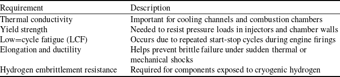


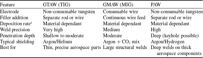


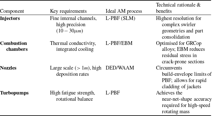


 Open access

