I. INTRODUCTION
In recent years, the increasing need for electronic products and devices in wireless communication tools, local area networks, health care and defense sectors, and other communication equipments has led to a novel kind of pollution known as electromagnetic interference (EMI). Meanwhile, many problems have occurred along with it, for example, misoperation of precise electronic equipment and leakage of secret information occurred by the EMI, etc. Thus, EMI has become a serious problem, and much attention has been paid toward finding a suitable electromagnetic wave (EMW) absorber with wider absorbing bandwidths to solve these problems.Reference Meshram, Agrawal, Sinha and Misra1, Reference Feng, Qiu, Shen and Li2
EMW absorbers can be classified into three kinds based on their loss mechanism, namely resistor type, dielectric type, and magnetic-media type. The first type materials include graphite, conducting polymers, silicon carbide, etc. They usually have high dielectric loss factors in the high-frequency band and attenuated EMW by the electronic polarization or interfacial polarization. Dielectric materials such as barium titanate, ferroelectric ceramics, etc. belong to the second type. They have considerable absorbing bandwidth, but their applications are limited for the high intensity and cost. The third type absorbers are the magnetic-media type materials. Ferrites are relatively typical ones that have higher magnetic loss factors and attenuated EMW by the mechanism of magnetic hysteresis loss, domain-wall resonance, and natural resonance. Though they have strong absorbing capacity and broad absorbing bandwidth, their applications are also limited due to high intensity, bad temperature stability, and poor absorbing efficiency in lower frequency range.
An “ideal” EMW absorber owns such advantages as minute thickness, low density, wide bandwidth, and flexibility simultaneously. However, the above-mentioned monocomponent absorbers cannot meet the required standard of an “ideal” EMW.Reference Mo, Sun, Chen, Zhang, Zuo and Liu3–Reference Wang, Bao, Yang and Chen5 For the purpose of preparing a low-reflection absorber in the desired frequency range, two fundamental conditions must be satisfied.Reference Zhang, Feng, Xiong, Yang and Lu6 The first is that the incident wave can enter deeper in the absorber (impedance matching characteristic), and the second is that the EMW entering into the materials can be almost entirely attenuated and absorbed within the finite thickness of the absorber (attenuation characteristic). Efforts have been made to investigate the absorption property of monocomponent EMW absorbers, for instance, ferrite, conducting polymer, and other new absorption materials.Reference Lima, Pinho, Gregori, ReisNunes and Ogasawara7–Reference Fan, Yang, Li and Zou10 Recently, much attention has been paid to the polyaniline (PANI)/ferriteReference Li, Jiang and Xu11–Reference Liu and Wan14 and carbon/PANI composites with organized structures, which have a notable synergistic behavior between each component.Reference Wu, Ting, Wang, Yang and Tsai15–Reference Ting, Wu, Wang, Ho and Shih17 These binary composites can be used as EMW absorbing and shielding materials due to their multifunctional electrical and magnetic properties and good shielding effectiveness for various electromagnetic sources. However, ferrites and their composites for practical application have been restricted due to their higher density. A new approach have been proposed and carried out to reduce the density of the ferrites composites and keep the electromagnetic loss of the composite materials unchanged by partly substituting the composite materials by low-density carbon materials [for instance, activated carbon, expanded graphite (EG), and carbon nanotubes] due to their excellent dielectric loss.
To the best of our knowledge, there are few reports on the synthesis of ferrites/carbon composites with the function of shielding and absorbing EMW. The fabrication of the ternary EMW absorbers of EG, PANI, and ferrite with low reflection in wide-frequency band has not been achieved so far either.
Herein, we reported the preparation of EG/cobalt ferrite (CF) and EG/CF/PANI ternary composites which could be excellent candidates for EMW absorber with high absorption efficiency, wide bandwidth, and light weight.
II. EXPERIMENTAL
Fe(NO3)3·9H2O, Co(NO3)2·6H2O, aniline (An), dodecyl benzenesulfonic acid (DBSA), ammonium persulfate (APS), sodium hydroxide (NaOH), and absolute ethanol were all provided by the Sinopharm Chemical Reagent Co., Ltd. (Shanghai, China). Expandable graphite was received from the Qingdao Baichuan Graphite Company Ltd. (Qingdo, China). All of the reagents were of analytical grade. Aniline was used after purification by vacuum distillation, and the others were used as received.
A. Preparation of ternary composites EG/CF/PANI
EG was obtained by thermal treatment of expandable graphite at 700 °C for 1 min in a muffle furnace. The mixture of 1.0 g EG and 60 mL absolute ethanol was stirred vigorously in a flask for 1 h and then treated by ultrasonication for 10 h. The final EG was collected by vacuum filtration and dried to constant weight at 80 °C.
EG/CF composites with mass ratios of 0.2 to 1.5 of EG to CF (m EG/m CF) were synthesized by a coprecipitation method.Reference Feng, Sun, Fujii, Wu, Niihara and Yoshino18 In a typical procedure for preparing an EG/CF composite with m EG/m CF of 0.2, Fe(NO3)3·9H2O (3.444 g) and Co(NO3)2·6H2O (1.240 g) weighed according to the stoichiometric amounts of 1.0 g CF were dissolved in distilled water and then added to 60 mL of absolution ethanol containing 0.2 g of EG. Subsequently, 1 M of NaOH solution was added dropwise to the above solution till pH = 10; the obtained mixture was kept at 80 °C for 2 h under mechanical stirring. The collected solid precipitate was washed three times with deionized water and ethanol. Finally, it was dried for 6 h at 80 °C and sintered for 2 h at 300 °C. For comparison, a series of EG/CF composites with m EG/m CF of 0.4, 0.6, 0.8, 1.0, 1.2, 1.4, and 1.5 were prepared.
The ternary composites EG/CF/PANI consisted of EG/CF composite with m EG/m CF of 0.8 and PANI were prepared by in-situ polymerization.Reference Kinlen, Liu, Ding, Graham and Remsen19 In a typical experimental process, 0.9 g EG/CF composite and 0.1 g An were added to 60 mL of 0.01 mol/L DBSA aqueous solution. It was mechanically stirred for 0.5 h to form emulsion. Then, the APS solution was added dropwise into the emulsion, and the final emulsion was kept in an ice-bath for 12 h. The products were collected by vacuum filtration, washed thrice with ethanol and distilled water, and dried to constant weight at 80 °C. Finally, the EG/CF/PANI composite with PANI content of 10 wt% was obtained (based on the postulation of An polymerized entirely to form PANI). In another synthesis, a series of EG/CF/PANI composites with PANI content of 20, 40, 60, and 80 wt% were obtained under the same experimental conditions. For comparison, pure PANI was also prepared by the same process in the absence of EG/CF.
B. Characterization
The x-ray diffraction (XRD) patterns of the samples were obtained using an x-ray diffractometer (Philips-PW3040/60, Eindhoven, Netherlands) with Cu Kα radiation (λ = 0.154 nm). The morphologies of the composites were studied using scanning electron microscope (SEM, Hitachi S-4800, Tokyo, Japan). The electrical conductivities were carried out on a four-probe resistivity instrument (SDY-4, Sifangkeji Company, Guangzhou, China) at room temperature. A Lakeshore 7404 vibrating sample magnetometer (Lakeshore Cryotronics, Inc., Westerville, OH) was used to measure the magnetization of the samples in applied magnetic fields over the range of –15 to +15 kOe at room temperature. The composite powders were mixed with wax in the mass ratio of 1:1 to prepare rectangular coating layers of different thicknesses on square aluminum plates (18 × 18 × 0.6 mm3). Their complex permeability and permittivity were measured by a vector network analyzer (Agilent N5230, Agilent, Palo Alto, CA) in the range of 2–18 GHz at room temperature, and the EMW absorption properties of the samples of different thicknesses were analog calculated.
III. RESULTS AND DISCUSSION
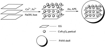
A schematic representation shown in Fig. 1 illustrates how to synthesize ternary EG/CF/PANI composites. First, the interspaces between the layers of EG are only a few nanometers wide and have an action similar to a capillary. The mixed nitrates solution corresponding to the CF composition filled the interspaces of EG, then the CF nanoparticles intercalate into the interspaces between the layers of EG in the coprecipitation process. It is followed by coating of PANI onto the surface of the EG/CF compound. As a result, EG/CF/PANI composites have a core–shell structure in which EG/CF serves as the core and PANI serves as the shell. In these composites, CF are typical magnetic loss materials and attenuated EMW by the mechanism of magnetic hysteresis loss, domain-wall resonance, and natural resonance; EG and PANI have higher dielectric loss in the high-frequency band and attenuated EMW by the electronic polarization or interfacial polarization.
Scheme of formation mechanism of expanded graphite/cobalt ferrite/polyaniline (EG/CF/PANI) composites.

A. X-ray diffraction
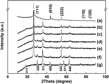
The XRD patterns of EG, CF, and EG/CF composites are presented in Fig. 2. The peaks at 26.69°, 43.90°, 54.83°, 77.76°, and 83.98° in Fig. 2(a) can be indexed to (111), (010), (222), (110), and (120) planes of EG, respectively, which coincide well with the standard literature values (JCPDS no. 75-2078). The peaks of CF ferrite presented at 18.37°, 30.34°, 35.52°, 43.17°, 53.70°, 57.14°, and 62.76° in Fig. 2(g) correspond to (111), (220), (311), (400), (422), (511), and (440) diffraction, respectively, which are indexed as a single spinel structure with the characteristic reflections of the Fd3m cubic group (JCPDS no. 22-1086). It is confirmed that the main diffraction peaks of EG and CF could also be observed in the XRD patterns of the EG/CF composites [Figs. 2(b)–2(e)]. For the composites, the peak intensities of EG are stronger than those of the pure EG, whereas the intensities of CF diffraction peaks are weaker than those of the pure CF. It may be because CF particles distributed in EG interlayers lead to some interactions between EG and CF.
X-ray diffraction (XRD) patterns of (a) EG, EG/CF composites with m EG/m CF of (b) 0.2, (c) 0.4, (d) 0.6, (e) 0.8, and (f) 1.0 and (g) CF composites.

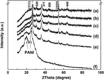
Figure 3 shows the XRD patterns of EG/CF/PANI composites and pure PANI. It can be seen from Figs. 3(a)–3(e) that there are eight diffraction peaks shown at 20.27°, 25.39°, 26.69°, 30.34°, 35.52°, 43.17°, 54.83°, and 62.76° in EG/CF/PANI composites. Comparing Fig. 2 and Fig. 3(f), it is obvious that the peaks at 26.69° and 54.83° are attributed to (111) and (222) planes of EG (marked in parentheses), and the peaks at 30.34°, 35.52°, 43.17° and 62.76° are attributed to (220), (311), (400), and (400) planes of CF. Figure 3(f) shows broad peaks of PANI located at 20.27° and 25.39°, which are ascribed to the parallel and perpendicular periodicity of the PANI chains, respectively.Reference Sauzedde, Elaissari and Pichot20 Based on the XRD analysis of as-prepared ternary composites, we can confirm the formation of EG/CF/PANI composites. The peak intensities of PANI in the composites are improved with increasing of PANI content.
XRD patterns of EG/CF/PANI composites with PANI content of (a) 10%, (b) 20%, (c) 40%, (d) 60%, and (e) 80% and (f) PANI composites.

B. Morphology characterization
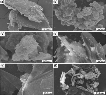
The SEM images of EG, CF, PANI, EG/CF, and EG/CF/PANI composites are presented in Fig. 4. EG, tens of micrometers in size [Fig. 4(a)], is composed of some multilayer graphite structures along the c-axis; the interspaces between two layers are large enough to be occupied by CF particles. As shown in Fig. 4(b), a spherical CF particle is ∼500 nm in average size and agglomerated to some extent due to the high surface energy and interaction among the magnetic particles. It can be seen from Figs. 4(d) and 4(e) that the typical layer structure of EG is kept well in EG/CF composites, and the spherical CF particles with an inhomogeneous distribution in size grow on EG surface with intercalation compounds forming in their interspaces. The EG/CF composites are coated by the PANI particles [Fig. 4(c)] to form core–shell structural EG/CF/PANI composites with EG/CF particles as a core and PANI as a shell [shown in Fig. 4(f)]. This is in accordance with the result of XRD analysis.
Scanning electron microscope (SEM) images of (a) EG, (b) CF, (c) PANI, and (d, e) EG/CF composites and (f) EG/CF/PANI composites with PANI content of 40 wt%.

C. Electrical conductivity
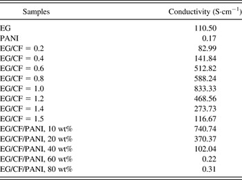
The electrical conductivity of EG, PANI, EG/CF composites, and EG/CF/PANI composites are shown in Table I. The conductivities of EG/CF composites are gradually enhanced firstly and decreased then with increase in weight ratio of EG to CF (m EG/m CF) because CF possess a great electrical resistivity to an order of magnitude of 104, while EG is a good electrical conductor.
The electrical conductivities of expanded graphite (EG), EG/cobalt ferrite (CF), and EG/CF/polyaniline (PANI) composites.

The conductivities of EG/CF composites with m EG/m CF of 0.4 to 1.4 are larger than that of pure EG though the conductivity of EG is already unexpectedly good. The possible reason is that the CF is intercalated into the space of the EG layers, carbon atoms can be transferred into the interstitial void of the CF conversely because of the Van der Waals forces between the CF and the EG, which cause CF to transform from insulator to semiconductor and can be better explained by percolation theory.Reference Stauffer21
Hence, CF in the space of EG layers plays the role of a bridged linkage, resulting in the EG valence band locating in the middle of the conduction band and empty band. So the forbidden band of the EG is diminished. As a result, the conductivity of EG/CF composites increases dramatically and reaches the maximum to m EG/m CF of 1.0. However, as the value of m EG/m CF is further increased, the conductivity of EG/CF composites decreases gradually and is already close to that of pure EG till m EG/m CF of 1.5.
As shown in Table I, the conductivity of EG/CF/PANI composite with 10 wt% PANI is larger than that of EG/CF composite with m EG/m CF of 0.8, and it is the maximum among all the EG/CF/PANI composites. The conductivities of EG/CF/PANI composites decrease with increasing PANI content and become almost unchangeable when PANI content > 60 wt%. On the one hand, when PANI content ≥ 60 wt%, the PANI may fully cover the EG/CF particles; this may result in similar conductivities as that of PANI. On the other hand, when PANI content < 20 wt%, the coverage of PANI on EG/CF particles may be incomplete. Because the intercalation compounds of EG/CF have good electrical conductivity, and PANI provides a lot of conductive pathway on its surface, the synergistic effect between them enormously improves the conductivity of EG/CF/PANI composites as a result.
D. Magnetic property
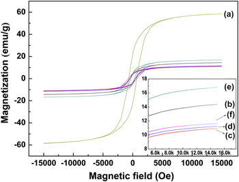
The hysteresis loops of EG/CF composites are shown in Fig. 5. Generally, saturation magnetizations (M s) of the composites are smaller than that of pure CF because the M s of the EG/CF composites depend on the volume fraction of the magnetic CF particles.Reference Sauzedde, Elaissari and Pichot20 EG is nonmagnetic and plays the part of isolating the CF particles. The volume fraction of CF particles in the composites declines because of the added EG, resulting in decrease in M s. Furthermore, the magnetic interactions among CF particles become weaker because of the isolating effect of EG, and the domain boundary displacements of CFs become easier. These two reasons also make the coercivities (H c) of the composites decrease. In addition, the surface anisotropy of the composites will result in the increase of H c. Ultimately; H c decreases first and then increases. M s of the composite with m EG/m CF of 0.8 is the largest among EG/CF composites (shown in Table II). It is perhaps caused by the synergistic effect between EG and CF at this mass ratio. Hence, the composite with m EG/m CF of 0.8 is chosen to prepare the EG/CF/PANI composites.
Magnetic hysteresis loops of (a)‐(f) the composites with m EG/CF from 0 to 1 (step = 0.2).

M s and H c of CF, EG/CF, and EG/CF/PANI composites.

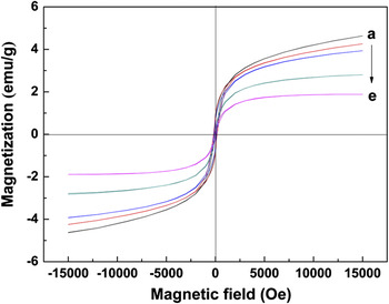
Figure 6 shows that the M s of EG/CF/PANI composites decrease gradually with increase of PANI content, which is attributed to the decrease of CF particles. It is known that M s of the EG/CF/PANI composites is not only related with the volume fraction of CF particles but also the demagnetizing field caused by EG and PANI. For one thing, according to M s = φm sReference Sauzedde, Elaïssari and Pichot22 (M s the saturation magnetizations of the composites; φ the volume fraction of magnetic particles; m s the saturation magnetizations of a single magnetic particle), the more volume fraction of CF particles, the more M s of EG/CF/PANI composites; for another, the isolating effect of EG and PANI becomes stronger as their volume fraction increases, and the demagnetizing field induced by this results in M s of EG/CF/PANI composites decreases.
Magnetic hysteresis loops of EG/CF/PANI composites with PANI content of (a) 10%, (b) 20%, (c) 40%, (d) 60%, and (e) 80%.

The H c of the composites is related to several factors, such as morphology, grain shape, component, anisotropy (magnetocrystalline, stress, shape), and magnetostriction. It can be seen from Table II that H c of EG/CF/PANI composites increases first, then decreases, and finally increases with increase of PANI content. PANI coating onto EG/CF particles during the polymerization process resulted in the interface effect between EG/CF particles and PANI chains; therefore, the surface anisotropy of EG/CF/PANI composites declined. Besides that, there may be some interaction between EG/CF particles and PANI chains, which would change the surface charge density and the electron spin mechanism of the EG/CF particles and weaken the resistance of domain wall displacement of CF particles in EG/CF composites. Therefore, the H c of composites shown in Table II is determined by the above factors.
E. EMW absorbing property
The EMW absorbing properties of materials can be defined by the reflection loss. The reflection loss (R) is calculated as R (dB) = 20 lg|(Z in − 1)/(Z in + 1)|, where Z in is the normalized input impedance relating to the impedance in free space.  and
 are the relative complex permeability and permittivity of the absorber medium, respectively. The impedance matching condition is determined by the combinations of six parameters ε′, ε″, μ′, μ″, f (the frequency of EMW), and d (thickness of sample layer absorber). Additionally, light weight, high strength, thin thickness, wide bandwidth, and high absorbing performances are used to evaluate the absorbers in engineering application. In this article, the available bandwidth is defined as the frequency width in which R is less than −8 dB.
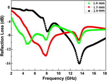
Figure 7 shows the R of EG/CF composites with m EG/m CF of 0.8 in layers of different thicknesses. In all samples, the peaks of R appear in the range of 2–18 GHz, in which the sample with a thickness of 2.0 mm has the minimum R of –16.08 dB at 13.52 GHz and the available bandwidths of 6.6 GHz, and the minimum R shifts to high frequency with increase of thicknesses. The EMW absorbing property of EG/CF composites depends on their magnetic and dielectric loss.Reference Wei, Liu and Li23, Reference Ni, Wang, Zhou, Yang, Wang and He24
R (dB) of EG/CF composites with m EG/CF of 0.8 in layers of different thicknesses.

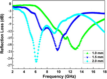
Figure 8 illustrates the R of EG/CF/PANI composites with 40 wt% PANI in layers of different thicknesses. Samples of 1.0, 1.5, and 2.0 mm thickness have the minimum R of −20.04, −20.33, and −25.37 dB at 12.96, 9.76, and 6.08 GHz, and the available bandwidths of 8.62, 6.15 and 7.82 GHz, respectively. It is worth noting that the minimum R of the sample with the layer of 2.0 mm thickness has still less than –8 dB after 18 GHz, which means this sample has favorable absorbing performance in the high band (>18 GHz).
R (dB) of EG/CF/PANI composites with 40 wt% PANI in layers of varied thicknesses.

It can be seen from Fig. 8 that the frequency corresponding to the minimum R value shifts negatively when the thickness of EG/CF/PANI composites increase from 1.0 to 2.0 mm. According to one of the parameter requirements for zero-reflection, the microwave frequency and the thickness of the absorbing layer should satisfy f = c/2πμ r″d,Reference Xu, Han, Jiang, Wang, Li and Wen25, Reference Xu, Han, Wang, Zhou, Lv, Wen, Wang and Zhang26 where μ r″ is the imaginary part of relative permeability μ r, d is the thickness of sample layer. Therefore, the frequency corresponding to the minimum R value can be modulated by d and μ r″ of the prepared EG/CF/PANI composites.
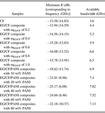
The minimum R value and available bandwidth of CF, EG/CF, and EG/CF/PANI composites with the thickness of 2 mm are shown in Table III in the range of 8–18 GHz. The minimum R values of all EG/CF composites are less than that of CF, and their available bandwidth is more than that of CF. As increasing of m EG/CF value, the minimum R value of EG/CF composites lowers, but available bandwidth increases. When the value of m EG/CF is equal to 0.8 in the EG/CF composites, a minimum R value of −16.08 dB appears at approximately 13.52 GHz, and an available bandwidth is broaden to 6.6 GHz. However, as the value of m BFA/m OT increases to 1.0, the microwave absorption properties of the composite weaken. The absorbing property of all EG/CF/PANI composites excelled those of EG/CF composites. When relative content of PANI in EG/CF/PANI composites is up to 40 wt%, a minimum R value of −25.17 dB appears at approximately 6.08 GHz, available bandwidth is broadened to 7.82 GHz. As PANI content is equal to or more than 60 wt% in the composites, the EMW absorption properties of the composites become poorer. The results imply that the absorbing property of the EG/CF/PANI composites can be modified by moderate content of conducting polymer.
The minimum R and the available bandwidth for CF, EG/CF, and EG/CF/PANI composites with thickness of 2 mm.

It is well known that EG and PANI are dielectric loss absorbents, and CF is a magnetic loss absorbent. Within the GHz range, the permittivity of the ferrite is almost a constant, for its imaginary parts close to 0, and its dielectric loss is almost negligible. As a result, its absorbing performance mainly depends on the magnetic loss. Although both the domain-wall resonance and the spin-rotation resonance make contributions to the complex permeability, only the spin-rotation resonance makes major contributions to the magnetic loss.Reference Kwon, Shin and Oh27 Meanwhile, the magnetic loss of EG and PANI can almost be negligible, their microwave absorption properties can be explained in terms of electrical conductivity and presence of bound/localized charges (polarons/bipolarons) leading to strong polarization and relaxation effects.Reference Stafström, Brédas, Epstein, Woo, Tanner, Huang and MacDiarmid28, Reference Zuo, Angelopoulos, MacDiarmid and Epstein29 As CF and EG combined, the interfacial and relaxation effects promoted the magnetic moment M to deviate from the easy magnetization axis and engender Larmor precession D. When the frequency of the alternating field is equal to the natural frequency ω of the precessional motion, EG/CF composites absorb a lot of energy provided by the alternating field, and so the magnetic moment M carries out forced vibration which is called the resonance phenomenon. The R value of EG/CF/PANI composites is also related to the dielectric loss of EG and PANI, and the magnetic loss of CF as well as the interfacial polarization between components. The coating of PANI hastens these effects and promotes the magnetic moment M to deviate from the easy magnetization axis and engender Larmor precession D, and as PANI content increases, the R peaks move to the low-frequency field. Hence, the synergistic effect of these factors would prompt remarkably the reflection loss of the EG/CF/PANI composites on EMW in high frequency. As PANI content increases further, the synergistic effect between components weaken due to complete coating, as a result, their EMW absorption properties become poorer conversely.
In a word, the microwave absorbing property of the EG/CF/PANI composites is a summation of the dielectric loss of POT (PMT) with the bound/localized charges, the dipolar reorientation processes, and the magnetic loss of BFA with the spin-rotation resonance as well as the interfacial polarization and relaxation effects between components. It is determined by the combinations of six parameters ε′, ε″, μ′, μ″, f, and d.
IV. CONCLUSION
In summary, EG/CF and EG/CF/PANI composites were successfully synthesized by coprecipitation and in-situ polymerization, respectively. Compared with CF, EG, and EG/CF composites, EG/CF/PANI composite with 10 wt% PANI has the maximal conductivity. The EMW absorbing property of all EG/CF/PANI composites excelled those of EG/CF composites, and the sample with 40 wt% PANI has the best absorption properties. It is of great importance to potential and valuable application in EMW shielding and absorption.
ACKNOWLEDGMENTS
This work was financially supported by the National Nature Science Foundation of China (21071125, 21101140), the Natural Science Foundation of Zhejiang Province (Y4080417, 4110025), and the Science and Technology Key Project of Zhejiang Province (2010C11053).