1. Introduction
External kink mode (EX) instability, which is often driven by the plasma pressure, has long been well known as a primary factor limiting the operational space of steady-state advanced tokamak devices (Kessel et al. Reference Kessel, Manickam, Rewoldt and Tang1994; Aymar, Barabaschi & Shimomura Reference Aymar, Barabaschi and Shimomura2002). Fortunately, EX can be completely suppressed by a closely surrounding, perfectly conducting wall. In reality, the wall (often the vacuum vessel or stabilizing plates) has finite resistance. But still the growth rate of the mode can be greatly reduced, often by several orders of magnitude, by the presence of a highly conducting wall. The resulting residual instability, which is called the resistive wall mode (RWM) (Chu et al. Reference Chu, Greene, Jensen, Miller, Bondeson, Johnson and Mauel1995; Ward & Bondeson Reference Ward and Bondeson1995; Bondeson & Xie Reference Bondeson and Xie1997; Chu & Okabayashi Reference Chu and Okabayashi2010), grows on the resistive time scale of the wall, as the eddy currents in the wall decay. This simple picture holds within the ideal single-fluid, magnetohydrodynamic (MHD) theory, in the absence of any additional damping mechanisms from inside the plasma.
Research on the plasma-induced RWM damping has been carried out for about two decades. A differential rotation between the plasma and the resistive wall was found to suppress the mode by Bondeson & Xie (Reference Bondeson and Xie1997). Later on, Chu et al. (Reference Chu, Greene, Jensen, Miller, Bondeson, Johnson and Mauel1995) found that the flow damping of the RWM requires synergistic effects with certain dissipation physics, such as parallel viscous damping. At present, two mainstream methods are envisaged for the RWM stabilization. One is the active control technique utilizing magnetic coil systems (Fransson et al. Reference Fransson, Lennartson, Breitholtz, Bondeson and Liu2000; Liu & Bondeson Reference Liu and Bondeson2000; Bondeson et al. Reference Bondeson, Liu, Fransson, Lennartson, Breitholtz and Taylor2001; Liu et al. Reference Liu, Bondeson, Gribov and Polevoi2004, Reference Liu, Bondeson, Chu, Favez, Gribov, Gryaznevich, Hender, Howell, LaHaye, Lister and de Vries2005a ,Reference Liu, Chu, Garofalo, LaHaye, Gribov, Gryaznevich, Hender, Howell, de Vries, Okabayashi, Pinches and Reimerdes b , Reference Liu, Chapman, Chu, Reimerdes, Villone, Albanese, Ambrosino, Garofalo, Gimblett, Hastie, Hender, Jackson, La Haye, Okabayashi, Pironti, Portone, Rubinacci and Strait2009, Reference Liu, Chu, Guo, Villone, Albanese, Ambrosino, Baruzzo, Bolzonella, Chapman, Garofalo, Gimblett, Hastie, Hender, Jackson, La Haye, Lanctot, In, Marchiori, Okabayashi, Paccagnella, Furno Palumbo, Pironti, Reimerdes, Rubinacci, Soppelsa, Strait, Ventre and Yadykin2010; Drake et al. Reference Drake, Brunsell, Yadikin, Cecconello, Malmberg, Gregoratto, Paccagnella, Bolzonella, Manduchi, Marrelli, Ortolani, Spizzo, Zanca, Bondeson and Liu2005; Gregoratto et al. Reference Gregoratto, Drake, Yadikin, Liu, Paccagnella, Brunsell, Bolzonella, Marchiori and Cecconello2005; Martin et al. Reference Martin, Apolloni, Puiatti, Adamek, Agostini, Alfier, Annibaldi, Antoni, Auriemma, Barana, Baruzzo, Bettini, Bolzonella, Bonfiglio, Bonomo, Brombin, Brotankova, Buffa, Buratti, Canton, Cappello, Carraro, Cavazzana, Cavinato, Chapman, Chitarin, Dal Bello, De Lorenzi, De Masi, Escande, Fassina, Ferro, Franz, Galo, Gazza, Giudicotti, Gnesotto, Gobbin, Grando, Guazzotto, Guo, Igochine, Innocente, Liu, Lorenzini, Luchetta, Manduch, Marchiori, Marcuzzi, Marrelli, Martini, Martines, McCollam, Menmuir, Milani, Moresco, Novello, Ortolani, Paccagnella, Pasqualotto, Peruzzo, Piovan, Piovesan, Piron, Pizzimenti, Pomaro, Predebon, Reusch, Rostagni, Rubinacci, Sarft, Sattin, Scarin, Serianni, Sonato, Spada, Soppelsa, Spagnolo, Spolaore, Spizzo, Taliercio, Terranova, Toigo, Valisa, Vianello, Villone, White, Yadikin, Zaccaria, Zamengo, Zanca, Zaniol, Zanotto, Zilli, Zohm and Zuin2009). The other can be called the passive control method, largely relying on additional energy damping often associated with the toroidal flow of the plasma. This work continues the passive control method line of research.
The mode resonates with stable continuum waves such as shear Alfven waves or sound waves (Chu et al. Reference Chu, Greene, Jensen, Miller, Bondeson, Johnson and Mauel1995), occurring at sufficiently fast plasma flow (at least a few percent of the Alfven speed), which taps the free energy associated with the mode, and can result in its suppression. Another important energy damping mechanism is associated with the kinetic resonances between the RWM and magnetic drift motions of plasma particles, as first pointed out by Hu & Betti (Reference Hu and Betti2004). Significant mode–particle resonance occurs when the plasma rotation frequency is in the same range as the trapped ion precessional drift frequency. Later on, experimental results from several tokamak devices, notably DIII-D (Reimerdes et al. Reference Reimerdes, Hender, Sabbagh, Bialek, Chu, Garofalo, Gryaznevich, Howell, Jackson, La Haye, Liu, Menard, Navratil, Okabayashi, Pinches, Sontag, Strait, Zhu, Bigi, de Baar, de Vries, Gates, Gohil, Groebner, Mueller, Raman, Scoville and Solomon2006, Reference Reimerdes, Garofalo, Jackson, Okabayashi, Strait, Chu, In, La Haye, Lanctot, Liu, Navratil, Solomon, Takahashi and Groebner2007) and JT-60U (Takechi et al. Reference Takechi, Matsunaga, Aiba, Fujita, Ozeki, Koide, Sakamoto, Kurita, Isayama and Kamada2007), found stable RWM at very slow plasma rotation speed (a fraction of a percent of the Alfven speed), indicating the important role played by the drift kinetic resonances.
In principle, the drift kinetic model can offer a range of possible mode–particle resonances for the RWM. In relatively fast plasma flow, the kinetic damping often comes from the mode resonance with the transit or bounce motion of thermal ions of the bulk plasma. At slow plasma rotation (below the ion diamagnetic flow speed), a strong damping often results from the mode resonance with toroidal magnetic precession of trapped thermal ions and electrons (Liu et al.
Reference Liu, Chu, Gimblett and Hastie2008; Chapman et al.
Reference Chapman, Gimblett, Gryaznevich, Hender, Howell, Liu and Pinches2009; Zheng, Kotschenreuther & Van Dam Reference Zheng, Kotschenreuther and Van Dam2009; Hao et al.
Reference Hao, Wang, Liu and Qiu2011, Reference Hao, Liu, Wang and Qiu2012; Wang, Guo & Liu Reference Wang, Guo and Liu2012). In addition, toroidal precession of trapped energetic ions can also contribute to the mode damping. One example is the stabilizing role played by the fusion-born
 ${\it\alpha}$
particles, which has been numerically investigated for one of the advanced steady-state scenarios in international thermonuclear experimental reactor (ITER) (Liu Reference Liu2010). Other recent interesting research topics on the kinetic-related RWM damping include the finite orbit width effects (Chapman et al.
Reference Chapman, Liu, Asunta, Graves, Johnson and Jucker2012), the synergetic effect with the resistive layer damping (He et al.
Reference He, Liu, Liu, Hao and Wang2014) and the three-dimensional drift kinetic response of high-b plasma in the DIII-D tokamak (Wang et al.
Reference Wang, Lanctot, Liu, Park and Menard2015).
In this work, we carry out a numerical study of the
 $n=1$
(
 $n$
is the toroidal mode number) RWM stability for an ITER 9MA steady-state plasma, based on the single-fluid MHD code MARS-F (Liu et al.
Reference Liu, Bondeson, Fransson, Lennartson and Breitholtz2000) and the hybrid kinetic–MHD code MARS-K (Liu et al.
Reference Liu, Chu, Chapman and Hender2008). The MARS-F model includes a parallel viscous force mimicking the ion Landau damping. The MARS-K code solves a self-consistent eigenvalue problem, which couples the single-fluid, linearized MHD equations with the perturbed kinetic pressure tensor, which in turn is semi-analytically derived for a generic toroidal geometry, and numerically solved as the solution of the linearized drift kinetic equation. The kinetic pressure tensor terms are represented in the form of kinetic integrals over the particle velocity phase space (eventually over the particle kinetic energy and the particle pitch angle).
The next section describes the ITER equilibrium adopted in this study, as well as the toroidal flow model. Section 3 briefly discusses the MARS-K formulation. Section 4 reports the numerical results, followed by the concluding section.
2. The equilibrium profiles and the rotation profiles
We adopt an equilibrium for a 9MA ITER steady-state scenario (Villone et al.
Reference Villone, Liu, Rubinacci and Ventre2010), with the major radius being
 $R_{0}=6.2~\text{m}$
and the on-axis vacuum toroidal field
 $B_{0}=5.3~\text{T}$
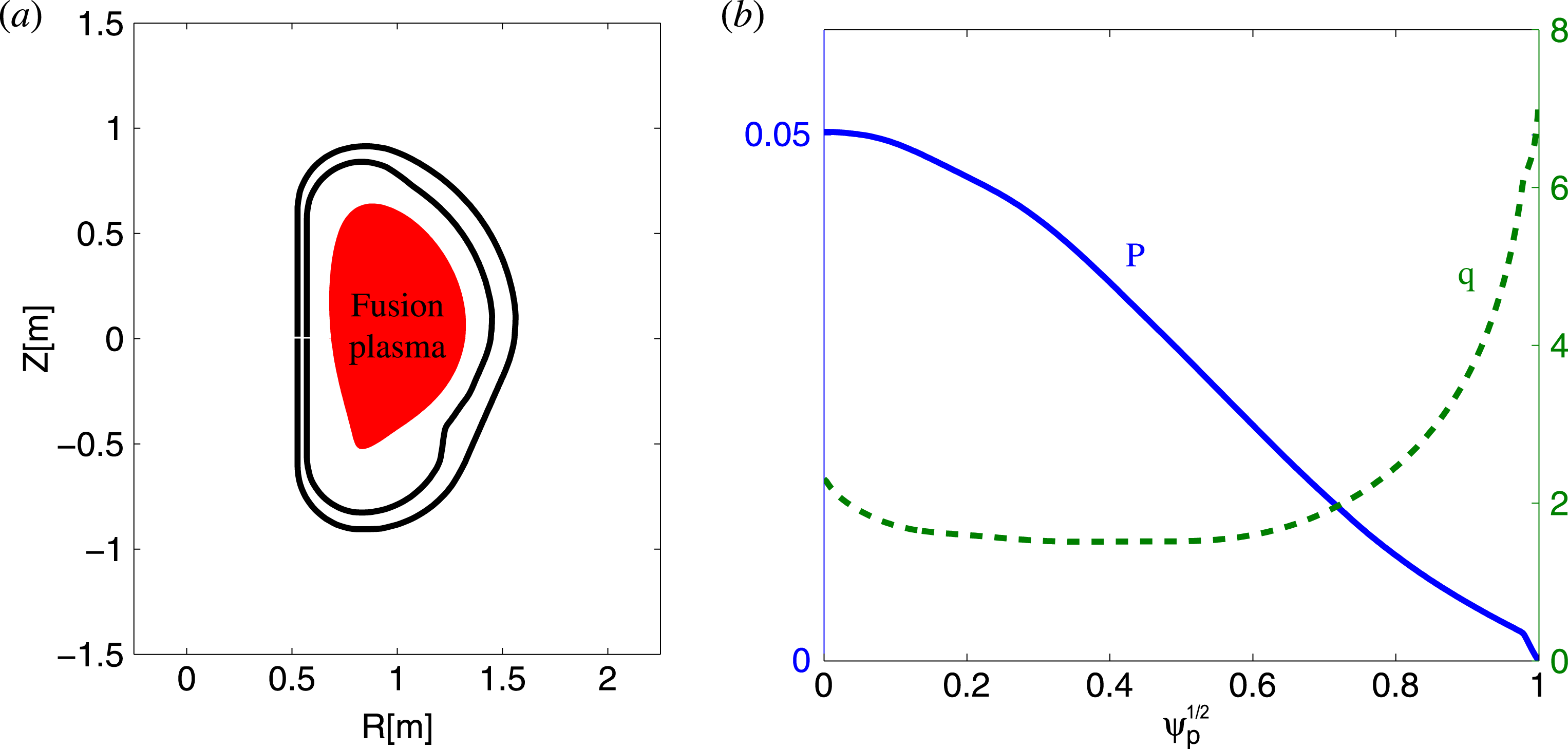
. Figure 1(a) shows the cross-section of a double-wall-shape ITER device, with the normalized pressure
 ${\it\beta}_{N}=3.21$
and (
 $R,Z$
) coordinates normalized by
 $R_{0}$
. The plasma boundary shape is smoothed near the X-point of the lower single null configuration by truncating the equilibrium, to alleviate numerical difficulty. The wall shape in this study is slightly simplified, being not exactly the same as the actual wall design. The thin-wall approximation is assumed, with about 0.3 s wall penetration time. Figure 1(b) shows the safety factor
 $q$
-profile, with reversed magnetic shear and
 $q_{min}\sim 1.5$
and
 $q_{edge}\sim 7.138$
. The plasma pressure, also shown, is normalized by the factor
 $B_{0}^{2}/{\it\mu}_{0}$
, where
 ${\it\mu}_{0}$
is the vacuum permeability. The equilibrium current is considered in this work, with a bootstrap current at the plasma edge. The
 $q$
-profile variation near the plasma edge due to the large bootstrap current can be found from the figure. The normalized poloidal magnetic flux is denoted
 ${\it\psi}_{p}$
.
The cross-section of the predicted ITER device shape and the equilibrium data adopted in this work (Wang et al. Reference Wang, Lanctot, Liu, Park and Menard2015). (a) The plasma boundary and the ITER double-wall shape, (b) the equilibrium pressure profile and the safety factor profile. The equilibrium profiles are calculated by using the CHEASE code.

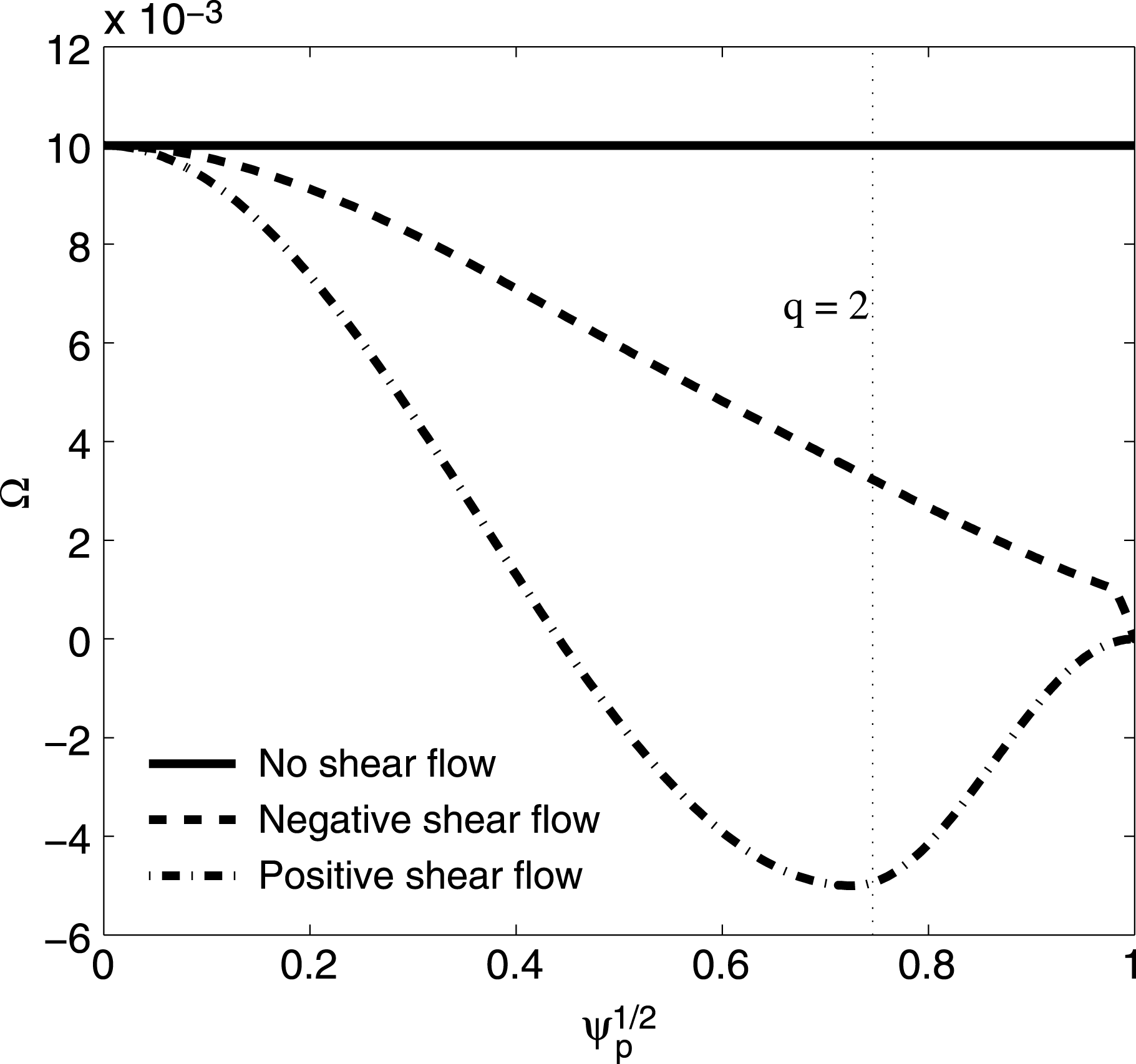
Three typical plasma rotation profiles are considered and shown in figure 2. Profile (a) is the uniform profile with no shear, profile (b) is the plasma rotation profile with negative shear at the rational surface
 $q=2$
and profile (c) is the plasma rotation profile with positive shear at the rational surface
 $q=2$
. Here profile (b) is the predicted rotation in ITER (Liu Reference Liu2010), while positive shear flow is chosen mainly for its theoretical interest. The reason for choosing these three rotation profiles is that they have different shear amplitudes and signs at rational surfaces
 $q=2,3$
. This is a very important research area in terms of rotational stabilization of MHD instabilities in fusion plasmas (Chu Reference Chu1998; Bierwage, Yu & Günter Reference Bierwage, Yu and Günter2007; Chapman et al.
Reference Chapman, Walkden, Graves and Wahlberg2011, Reference Chapman, Brown, Kemp and Walkden2012; Wahlberg, Graves & Chapman Reference Wahlberg, Graves and Chapman2013).
Three plasma rotation profiles with different shear directions at the
 $q=2$
rational surface (
 ${\it\psi}_{p}\sim 0.74642$
): no shear flow, negative shear flow and positive shear flow. The rotation speed is normalized by the Alfven speed
 ${\it\Omega}_{A}$
.

3. A brief introduction to the physics model in the MARS-K code
Here, we concentrate on investigating the parallel sound wave damping and the kinetic damping effects by using the self-consistent approach in the MARS-K code (Liu et al.
Reference Liu, Chu, Chapman and Hender2008, Reference Liu, Chu, Chapman and Hender2009). The stability of the RWM can be described by the quantity
 ${\it\omega}={\it\omega}_{r}+\text{i}{\it\gamma}$
, the complex mode frequency, where
 ${\it\omega}_{r}$
is the real frequency, and
 ${\it\gamma}$
is the growth rate. The MARS-K code basically solves the single-fluid linear MHD equations in the Eulerian frame as follows:
 $$\begin{eqnarray}\displaystyle (\tilde{{\it\gamma}}+\text{i}n{\it\Omega})\;{\bf\xi} & = & \displaystyle \boldsymbol{v}+({\bf\xi}\boldsymbol{\cdot }\boldsymbol{{\rm\nabla}}{\it\Omega})R^{2}\boldsymbol{{\rm\nabla}}{\it\varphi},\end{eqnarray}$$
 $$\begin{eqnarray}\displaystyle {\it\rho}(\tilde{{\it\gamma}}+\text{i}n{\it\Omega})\;\boldsymbol{v} & = & \displaystyle -\boldsymbol{{\rm\nabla}}\boldsymbol{\cdot }\unicode[STIX]{x1D665}-\boldsymbol{j}\times \boldsymbol{B}+\boldsymbol{J}\times \boldsymbol{b}-{\it\rho}[2{\it\Omega}\boldsymbol{Z}\times \boldsymbol{v}+(\boldsymbol{v}\boldsymbol{\cdot }\boldsymbol{{\rm\nabla}}{\it\Omega})R^{2}\boldsymbol{{\rm\nabla}}{\it\varphi}]\nonumber\\ \displaystyle & & \displaystyle -\,{\it\rho}{\it\kappa}_{\Vert }|k_{\Vert }|\boldsymbol{v}_{th,i}[\boldsymbol{v}\boldsymbol{\cdot }\boldsymbol{b}+({\bf\xi}\boldsymbol{\cdot }\boldsymbol{{\rm\nabla}})\boldsymbol{V}_{0}\boldsymbol{\cdot }\boldsymbol{b}]\;\boldsymbol{b},\end{eqnarray}$$
 $$\begin{eqnarray}\displaystyle (\tilde{{\it\gamma}}+\text{i}n{\it\Omega})\;\boldsymbol{b} & = & \displaystyle \boldsymbol{{\rm\nabla}}\times (\boldsymbol{v}\times \boldsymbol{B})+(\boldsymbol{b}\boldsymbol{\cdot }\boldsymbol{{\rm\nabla}}{\it\Omega})R^{2}\boldsymbol{{\rm\nabla}}{\it\varphi}-\boldsymbol{{\rm\nabla}}\times ({\it\eta}\boldsymbol{j}),\end{eqnarray}$$
 $$\begin{eqnarray}\displaystyle \boldsymbol{j} & = & \displaystyle \boldsymbol{{\rm\nabla}}\times \boldsymbol{b},\end{eqnarray}$$
 $$\begin{eqnarray}\displaystyle (\tilde{{\it\gamma}}+\text{i}n{\it\Omega})\;\unicode[STIX]{x1D665} & = & \displaystyle -\boldsymbol{v}\boldsymbol{\cdot }\boldsymbol{{\rm\nabla}}\unicode[STIX]{x1D665},\end{eqnarray}$$
 $$\begin{eqnarray}\displaystyle \unicode[STIX]{x1D665} & = & \displaystyle p\unicode[STIX]{x1D644}+p_{\Vert }^{kinetic}({\it\xi}_{\bot })\hat{\boldsymbol{b}}\hat{\boldsymbol{b}}+p_{\bot }^{kinetic}({\it\xi}_{\bot })(\unicode[STIX]{x1D644}-\hat{\boldsymbol{b}}\hat{\boldsymbol{b}}).\end{eqnarray}$$
These six equations reasonably well describe the RWM dynamics in the plasma region, where the lowercase letters
 ${\bf\xi},\boldsymbol{v},\unicode[STIX]{x1D665},\boldsymbol{b},\boldsymbol{j}$
represent the perturbation parameters; the uppercase letters
 ${\it\Omega},P,\boldsymbol{B},\boldsymbol{J}$
represent the equilibrium parameters. The parallel sound wave damping is introduced by the term including
 ${\it\kappa}_{\Vert }$
in (3.2).
In these equations:
 $\tilde{{\it\gamma}}={\it\gamma}-\text{i}{\it\omega}$
is the complex growth rate, where
 ${\it\gamma}$
is the mode growth rate and
 ${\it\omega}$
is the mode frequency;
 ${\it\eta}$
is the plasma resistivity;
 ${\bf\xi},\boldsymbol{v},\boldsymbol{b},\boldsymbol{j},\unicode[STIX]{x1D665}$
represent the plasma displacement, perturbed velocity, magnetic field, current and pressure tensor;
 ${\it\rho}$
is the unperturbed plasma density;
 $n$
is the toroidal number;
 ${\it\Omega}$
is the plasma rotation frequency along the toroidal angle
 ${\it\varphi}$
. The perturbed kinetic pressure tensor is given in (3.6), where
 $p$
is the scalar fluid pressure perturbation,
 $p_{\Vert }^{kinetic}({\it\xi}_{\bot })$
and
 $p_{\bot }^{kinetic}({\it\xi}_{\bot })$
are the parallel and perpendicular components of the kinetic pressure perturbations, respectively, and
 $\hat{\boldsymbol{b}}=\boldsymbol{B}/B,B=|\boldsymbol{B}|$
.
Equation (3.5) is the state equation of the kinetic model. It is obtained from the state equation of the fluid model:
 $(\tilde{{\it\gamma}}+\text{i}n{\it\Omega})\;p=-\boldsymbol{v}\boldsymbol{\cdot }\boldsymbol{{\rm\nabla}}P_{0}-{\it\Gamma}^{\ast }\boldsymbol{V}_{0}\boldsymbol{\cdot }\boldsymbol{{\rm\nabla}}p$
, where
 ${\it\Gamma}^{\ast }={\it\Gamma}(1-{\it\alpha}_{D})$
. Here,
 ${\it\alpha}_{D}$
is a kinetic model coefficient: when
 ${\it\alpha}_{D}=0$
the MHD equations are for the fluid model only, while when
 ${\it\alpha}_{D}=1$
and
 ${\it\kappa}_{\Vert }=0$
they are for the kinetic model only and the scalar pressure perturbation is replaced by the tensor pressure perturbation, given by (3.6).
There are two unique characteristics of the self-consistent approach which differ from those of the perturbative approach (Liu Reference Liu2010). (i) The self-consistent approach allows a self-consistent modification of the eigenfunction of the RWM, due to the presence of the kinetic terms. (ii) The growth rate (complex mode frequency) of the RWM enters self-consistently into the kinetic integrals, which makes the eventual eigenvalue problem nonlinear. A more detailed description of the MARS-K formulation and a systematic code bench-marking effort can be found in Chapman et al. (Reference Chapman, Gimblett, Gryaznevich, Hender, Howell, Liu and Pinches2009) and Berkery et al. (Reference Berkery, Liu, Wang, Sabbagh, Logan, Park, Manickam and Betti2014).
4. Results and discussion
The steady-state scenarios in ITER aim at advanced plasma performance with high pressure and high bootstrap current fraction. The target plasma is designed to slightly exceed the Troyn no-wall beta limit (Troyon et al.
Reference Troyon, Gruber, Saurenmann, Semenzato and Succi1984). Therefore, the first study we perform is to determine the value of the ideal MHD (no rotation, no viscosity, and no kinetic effects) no-wall beta limit and ideal-wall beta limit for these given equilibrium profiles. Note that when we scan the plasma pressure, the edge
 $q$
-value is fixed at 7.138, in order to keep the total plasma current unchanged.
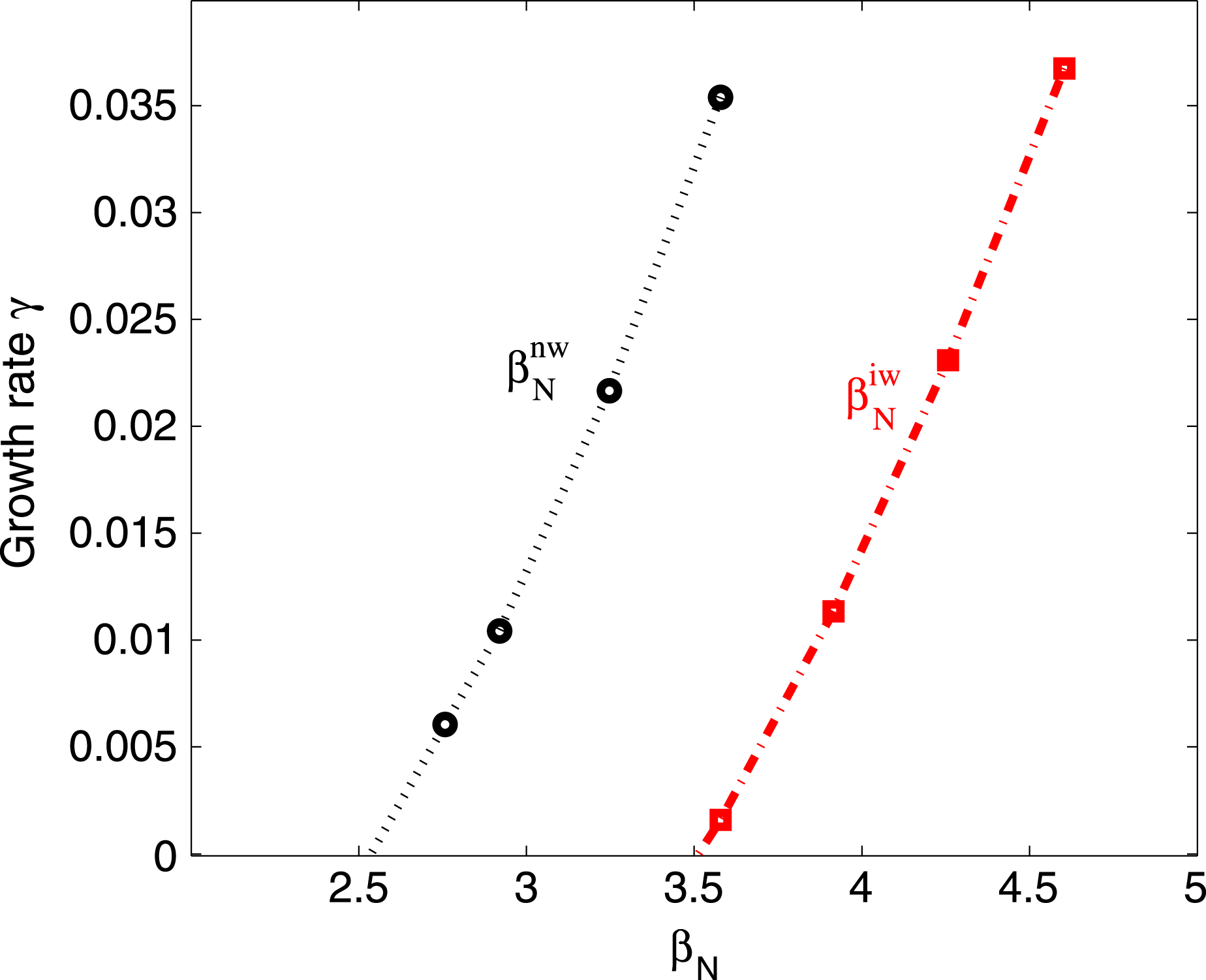
Both the ideal MHD no-wall beta limit and the ideal-wall beta limit can be computed and are shown in figure 3; it is 2.52 and 3.51 respectively. Then the pressure parameter
 $C_{{\it\beta}}=({\it\beta}_{N}-{\it\beta}_{N}^{no\text{-}wall})/({\it\beta}_{N}^{ideal\text{-}wall}-{\it\beta}_{N}^{no\text{-}wall})$
can be calculated in a set from 0 % to 100 %. In the parallel sound wave damping investigation, the pressure parameter is always set as
 $C_{{\it\beta}}=70\,\%$
.
Ideal MHD no-wall beta limit value and ideal-wall beta limit value,
 ${\it\beta}_{N}^{nw}=2.52$
,
 ${\it\beta}_{N}^{iw}=3.51$
.

Comparison of the eigenvalue branches with different shear flow at the
 $q=2$
rational surface,
 ${\it\kappa}_{\Vert }=1.0$
: no shear flow, negative shear flow and positive shear flow.

4.1. Parallel viscous force damping on RWM
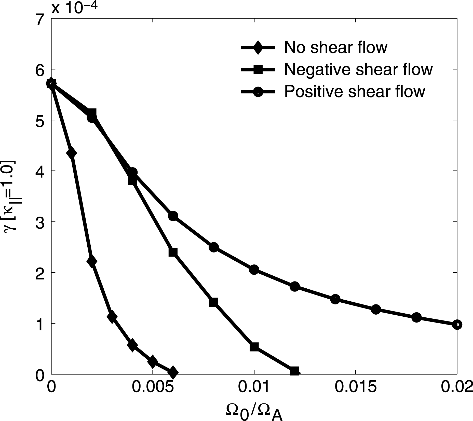
Figure 4 plots the growth rate for the three different rotation profiles. Here the resonance of the mode and ion parallel sound wave is considered as the only damping mechanism. The parallel viscous coefficient
 ${\it\kappa}_{\Vert }$
of this case is equal to 1.0. In figure 4, It can be seen that as the central rotation frequency is scanned, there are three significantly distinct curves of the growth rates (when varying the central rotation frequency the entire rotation profile is multiplied by a number). For uniform plasma flow, the modes are unstable when
 ${\it\Omega}_{0}\leqslant 0.005{\it\Omega}_{A}$
(
 ${\it\Omega}_{A}$
is the Alfven frequency). However, with increasing central rotation frequency we find that the damping appears. Eventually the modes are completely stable when
 ${\it\Omega}_{0}>0.007{\it\Omega}_{A}$
. For the cases of negative shear flow and positive shear flow, the unstable ranges are significantly wider. From the figure we can see that the plasma with negative shear flow becomes stable when
 ${\it\Omega}_{0}>0.013{\it\Omega}_{A}$
. However, the plasma with positive shear flow has no stable window appearing on the
 ${\it\Omega}_{0}$
-axis. The physical damping mechanism of the parallel viscous force is the mode resonating with the ion parallel sound wave, whose frequency is about a few percent of the Alfven frequency. Thus a sheared rotation profile effectively reduces the flow amplitude in the outer region of the plasma, which essentially weakens the stabilization of the plasma rotation.
Contour plots of the growth rate of the fluid RWM,
 $C_{{\it\beta}}=70\,\%$
. The black dot-dashed curves show the stability boundaries in the
 ${\it\kappa}_{\Vert }{-}{\it\Omega}_{0}$
plane. (a) No shear flow, (b) positive shear flow, (c) negative shear flow.

In order to perform a comprehensive physics study, the parallel viscous force effect on the RWM stability has been investigated in the 2D parameter space of (
 ${\it\Omega}_{0},{\it\kappa}_{\Vert }$
) for the three rotation profiles. Figure 5 shows the real part of RWM eigenvalues with varying parallel viscous coefficient and centre rotation frequency. The stable and unstable areas are separated by a contour line. The plasma uniform flow is considered to compute the eigenvalue and the result is shown in figure 5(a). It shows that the growth rate of the mode decreases along both the
 ${\it\kappa}_{\Vert }$
-axis and
 ${\it\Omega}_{0}$
-axis and the stable domain is clearly obvious. When the plasma rotation profile is replaced by negative shear flow, the result is again plotted in 2D space and shown in figure 5(b). We can see that the stable domain shrinks to a smaller domain with large values of (
 ${\it\Omega}_{0},{\it\kappa}_{\Vert }$
). Finally, we consider the plasma positive shear flow in the RWM eigenvalue computation. The result is given in figure 5(c), which clearly shows that there is no stable domain but the growth rates are damped by
 ${\it\Omega}_{0}$
and
 ${\it\kappa}_{\Vert }$
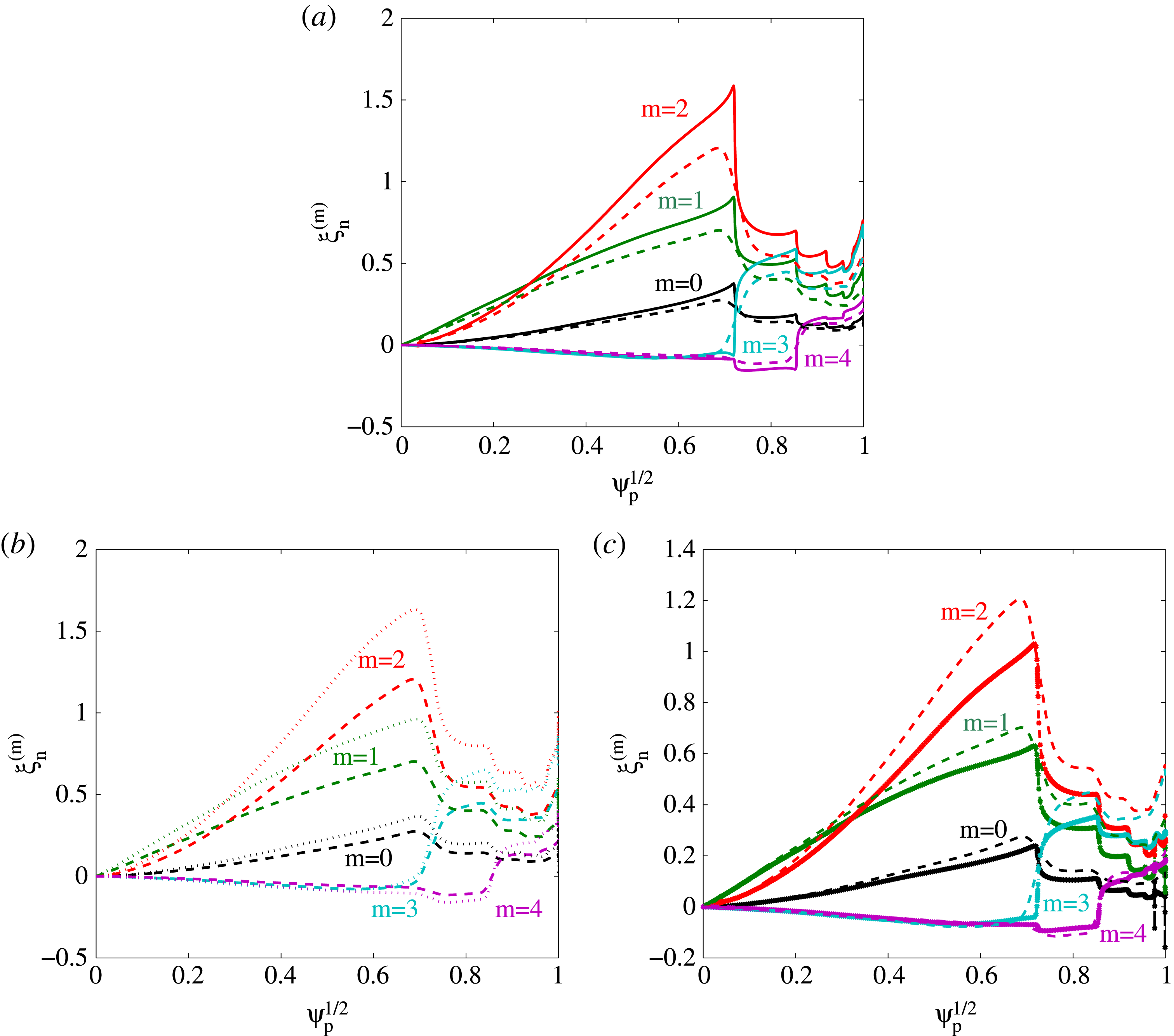
. Every eigenvalue shown in figure 5 has global, kink-like eigenmode structures. Figure 6(a–c) plots three sets of eigenfunctions for the three rotation profiles. A comparison between eigenfunctions with no plasma flow (solid) and with uniform plasma flow (dashed) is shown in figure 6(a). From the figure, it can be seen that the uniform plasma flow modifies the mode eigenfunction smoothly and globally. Figure 6(b,c) plot the eigenfunctions of plasma flow with positive and negative shear, compared to those without shear. The central rotation frequency and parallel viscous coefficient are chosen as
 ${\it\kappa}_{\Vert }=1.0,{\it\Omega}_{0}=0.01{\it\Omega}_{A}$
.
Comparison of the poloidal Fourier harmonics of eigenfunctions (the radial displacement) for (a) no shear flow (dashed) versus no flow (solid), (b) positive shear flow (dotted) versus no shear flow (dashed), and (c) negative shear flow (solid) versus no shear flow (dashed), computed by MARS-F for an ITER plasma with
 $C_{{\it\beta}}=70\,\%$
. An equal-arc flux coordinate system is used in the numerical computations.

From the above investigation, we find that no matter which plasma rotation profile is adopted, the minimum central rotation frequency for obtaining stabilized plasma is about 0.5 % of the Alfven frequency (
 ${\it\Omega}_{0}^{min}\sim 0.5\,\%{\it\Omega}_{A}$
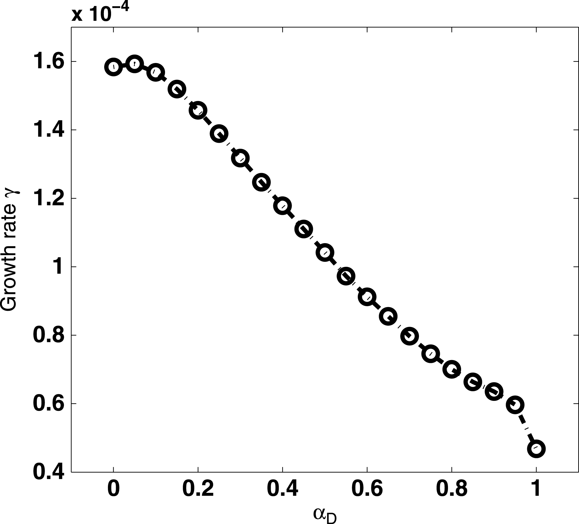
). If we want to obtain stabilized plasma with a lower central rotation frequency, another damping mechanism should be considered. Thus we focus on considering the effect of the magnetic precession drift resonance on RWM. The most important parameter is the critical rotation frequency (the critical rotation frequency is the minimal frequency required for the full suppression of the mode). The thermal particle magnetic precession drift resonance is the only damping effect we consider here. Figure 7 plots the growth rate obtained with both the fluid model and the kinetic model, at
 $C_{{\it\beta}}=70\,\%$
and with no plasma flow. From the figure we see a significant damping which is caused by increasing
 ${\it\alpha}_{D}$
. The growth rate of the mode with the kinetic model is much lower than that with the fluid model, when the same parameters are adopted, indicating a much lower critical rotation frequency with the inclusion of the kinetic effects.
The real part of the computed eigenvalue of the RWM versus the kinetic effect coefficient
 ${\it\alpha}_{D},C_{{\it\beta}}=70\,\%$
.

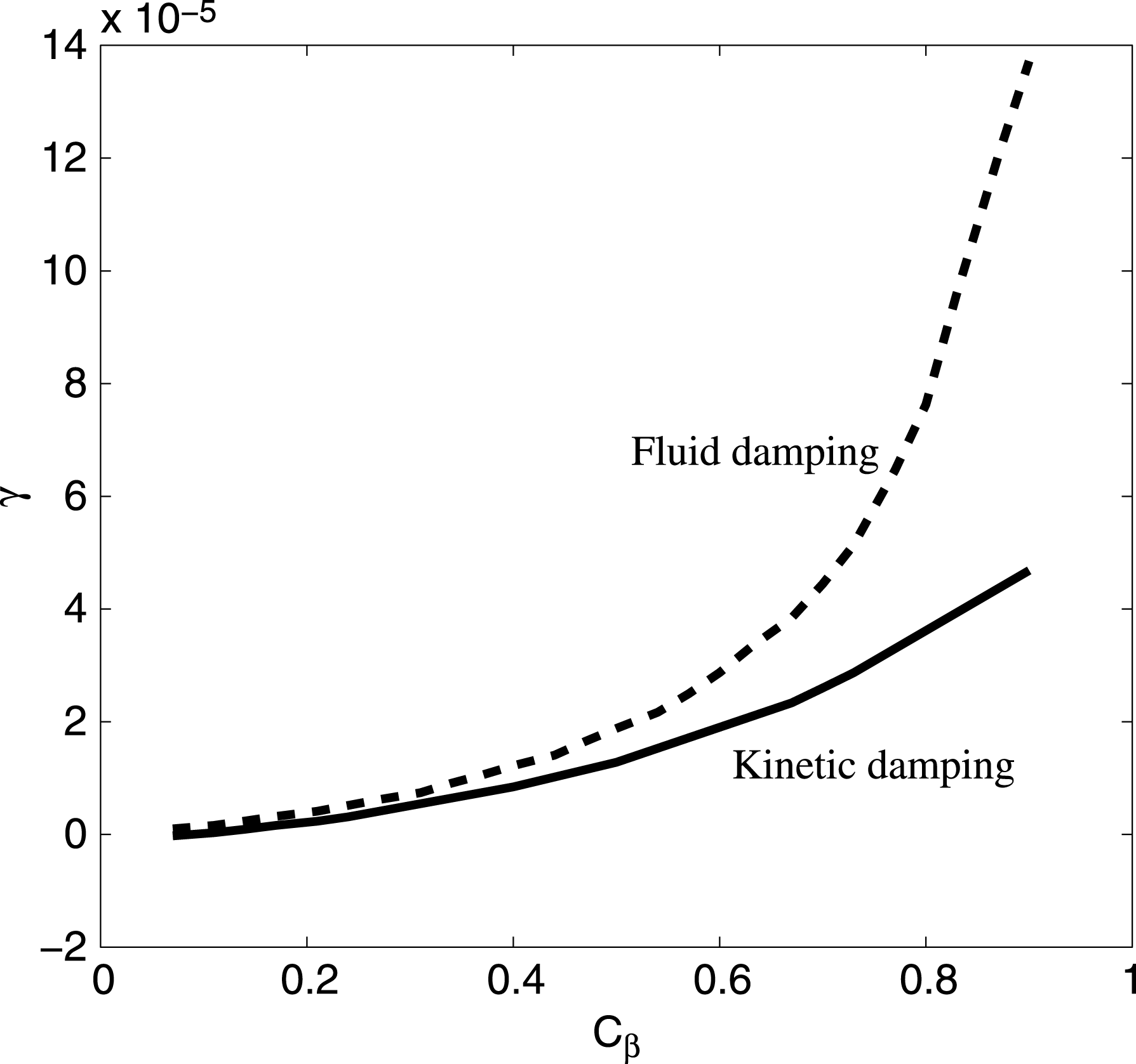
Comparison of the growth rate in the fluid model (dashed curve
 ${\it\Omega}=0$
) and the kinetic model (solid curve
 ${\it\Omega}=1\,\%{\it\Omega}_{A}$
) versus
 $C_{{\it\beta}}$
.

4.2. Drift kinetic damping on RWM
We fix
 ${\it\alpha}_{D}=1$
to do the further modelling. A comparison of the growth rate of the fluid and the kinetic models with different plasma pressure is shown in figure 8. Here we scan the growth rate along the
 $C_{{\it\beta}}$
-axis from 10 % to 90 % and obtain two growth rate curves using the fluid model at
 ${\it\Omega}_{0}=0$
, as well as with the kinetic model at
 ${\it\Omega}_{0}=1\,\%{\it\Omega}_{A}$
. Figure 8 shows that the growth rate of the kinetic model is always lower than that of the fluid model. The damping obviously occurs at the larger
 $C_{{\it\beta}}$
range. This result also proves that the kinetic model has a stronger damping than the fluid model. The RWM growth rates obtained from a 2D parameter (
 ${\it\Omega}_{0},C_{{\it\beta}}$
) scanning are shown in figure 9(a–c). The figures compare the stable domain under the three rotation profiles. The kinetic effect of magnetic precession drift is considered in a self-consistent approach. Comparing figure 9 to figure 5, we find that the mode is stabilized at a much lower central rotation frequency, no matter which rotation profile is assumed. From figure 9(a) we can see that the mode can be stabilized at a relatively large pressure. The same phenomenon does not appear in figure 9(b,c). For negative shear flow and positive shear flow, the critical plasma pressure is
 $C_{{\it\beta}}\sim 60\,\%$
. Figure 10(a–c) plots and compares three sets of eigenfunctions, at
 $C_{{\it\beta}}=90\,\%,{\it\Omega}_{0}=0.01{\it\Omega}_{A}$
. The eigenfunction is modified by the plasma rotation. The amplitude of the perturbed displacement is reduced globally for all rotation profiles.
Contour plots of the growth rate of the kinetic RWM; the black dot-dashed curves show the stability boundaries in the
 $C_{{\it\beta}}{-}{\it\Omega}_{0}$
plane. Different shear directions are considered for these three 2D plots and only precession drift resonance is included. (a) No shear flow, (b) positive shear flow and (c) negative shear flow.

Comparison of the poloidal Fourier harmonics of eigenfunction (the radial displacement) for (a) no shear flow (dash) versus no flow (solid) (b) positive shear flow (dot) versus no flow (solid) and (c) negative shear flow versus (dash-dot) no flow (solid), computed by MARS-K for an ITER plasma with
 $C_{{\it\beta}}=90\,\%$
. An equal-arc flux coordinate system is used in the numerical computations.

5. Conclusion
Effects of the parallel viscous force, as well as the drift kinetic damping, on the stability of the RWM is numerically investigated by using the MARS-F and the MARS-K codes, respectively, for an ITER 9MA steady-state plasma. Results with different plasma flow profiles are compared. Assuming a generally slow plasma flow in ITER, we consider the precessional drift resonance of thermal particles in the MARS-K model. The kinetic effect is included in the computations via a non-perturbative hybrid approach. The key findings are summarized as follows.
Firstly, the parallel viscous force induced damping becomes stronger with increasing rotation speed. The
 $n=1$
RWM is eventually fully stabilized at sufficiently high rotation frequency, for the cases of a uniform flow profile and a profile with negative shear. No full stabilization is found in the case of a profile with positive shear. The rotation amplitude plays a very important role here. A stable domain in the 2D space of (
 ${\it\Omega}_{0},{\it\kappa}_{\Vert }$
) is mapped out, and the change of the mode eigenfunction due to different flow profiles is also reported.
Secondly, for the ITER regime, the magnetic precessional drift resonance of thermal ions and electrons is non-perturbatively included in the MARS-K computations, resulting in a stable domain for the RWM in the 2D space of (
 ${\it\Omega}_{0},C_{{\it\beta}}$
). In contrast to the fluid model results, the critical rotation frequency of the kinetic model is much lower than that of the fluid model. That is because the mode resonates with the thermal particle precessional drift motion which has
 $\text{lower frequency}\sim 0.3\,\%{\it\Omega}_{A}$
.
This work does not cover all the drift kinetic effects associated with the RWM; in particular, we have neglected the bonce resonance of trapped bulk ions as well as the transit resonance of passing ions. These resonances normally become significant in fast plasma flow. The drift kinetic effects from energetic particles are also neglected. These are the subject of our future investigations.
Acknowledgements
We thank Professor Y. Q. Liu for his great help and also thank G. Xia and Y. He for their good suggestions. This work is funded by the National Natural Science Foundation of China (NSFC) [grant no. 11275041].